
Buyers searching for csa and ul listed membrane switches usually need a controlled component that supports certification of finished equipment—not a generic “approved” keypad. Start with the end-product standard and target country. Then confirm whether ANSI/UL 2557 applies, whether the exact switch or circuit construction has recognized evidence, and whether its Conditions of Acceptability match the installation. The OEM or certification applicant retains ownership of final approval. The decisive variables are circuit voltage and power, safety function, material grade and thickness, flex-circuit construction, mounting surface, environment, embedded components, production site, and change control.
Capacitive touch sensing on general 3D surfaces is feasible when the electrode pattern, formed substrate, adhesive, cover lens, display stack and controller are engineered as one assembly. It suits fixed, nonconductive curved interfaces that need sealed buttons, sliders or multi-touch input. The safe boundary is simple: do not release flat electrode artwork or tune firmware from a planar prototype before the final 3D stack is known. Local radius, compound curvature, draw direction, electrode stretch, print-to-form registration, air gaps, nearby metal, tail routing and environmental noise determine performance. For sharp re-entrant geometry, moving skins or poorly controlled bonding gaps, segment the interface or choose another sensing method.
An HMI panel for HVAC systems is the local hardware interface through which an occupant, technician, or building operator views conditions and changes permitted settings. The correct design depends on the task, installation tier, viewing distance, available panel area, gloves or moisture, display and touch stack, service route, physical BACnet or Modbus interface, and the party that owns commissioning. Specify the operator job first. Then release the front-panel drawing, enclosure boundary, connector state, environment, and validation plan. This guide covers manufacturable HMI hardware; PLC logic, SCADA development, control sequences, network commissioning, and whole-building performance remain system-level responsibilities.
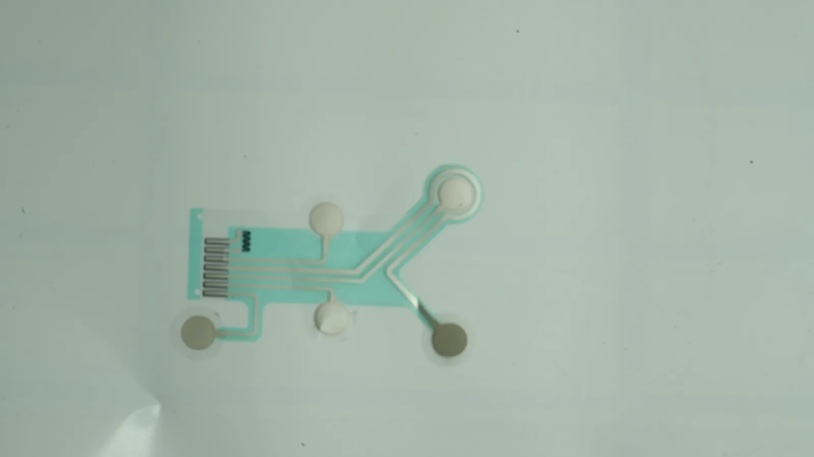
ANSI/AAMI EC12 disposable ECG electrodes should be selected as a complete, packaged interface—not by pad diameter or conductor label alone. For an OEM device, define the intended recording function, contact duration, electrode geometry, substrate, Ag/AgCl system, hydrogel or adhesive, connector, liner, package, shelf-life evidence and validation owner; EC12 supplies important labeling, safety and performance inputs, but it does not establish patient compatibility, clinical performance, finished-device approval or universal material specifications. The OEM must translate the intended use into a released stack and a risk-based verification plan.
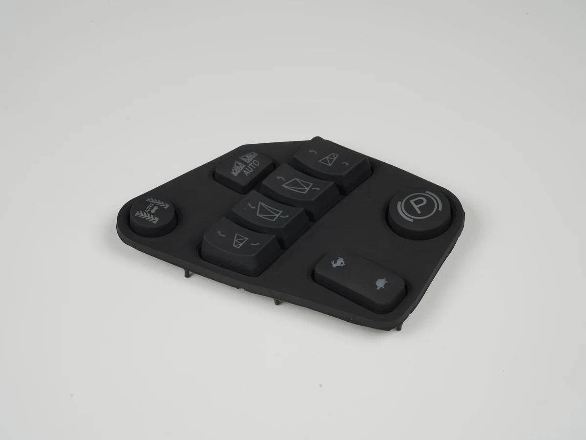
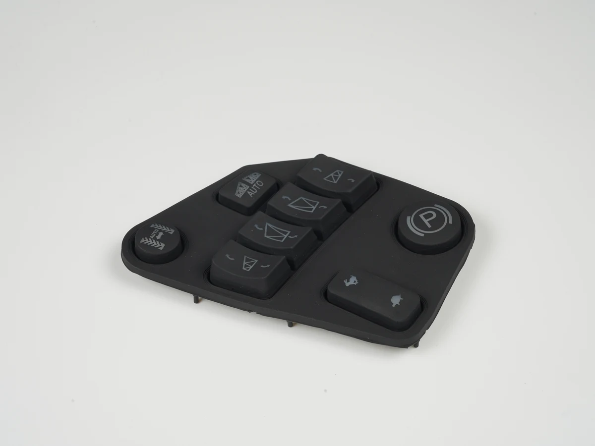
Silicone rubber keypad EMI shielding uses a conductive layer, filled elastomer, foil, mesh, or perimeter gasket to control electromagnetic coupling at the user-interface opening. It works only when the shield remains electrically continuous and has a defined bond to the equipment’s shield or chassis reference.
A normally closed membrane switch keeps electrical continuity in its defined rest state and opens when actuated. It suits OEM controls that need an open-on-press signal or want a broken conductor to produce the same input state as actuation. It does not make a machine safe by itself. Use an NC construction only after defining the physical rest state, controller thresholds, allowable closed-state current, contact-separation geometry, installation support and response to open and short faults. For power loads, safety interlocks, dense key matrices or battery products with a tight sleep-current budget, another switch architecture is usually the better choice.
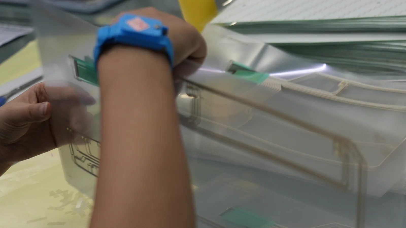
An HMI for chemical processing equipment should be specified as a complete, installed hardware stack—not simply as a touchscreen with an IP label. OEM engineers should select the front surface, touch method, adhesive, gasket, bezel, circuit, connector exit and enclosure interface from the named chemicals, concentrations, temperatures, contact modes, classified-area status, gloves, washdown method, lighting and maintenance plan. The defensible recommendation is layer-specific and system-specific: verify every exposed material and joint under representative conditions. IP protection, corrosion resistance, chemical compatibility and hazardous-location approval answer different questions. PLC/SCADA programming and process-control logic are outside this hardware guide.

HMI hardware for medical and pharmaceutical equipment should be specified as one controlled interface stack, not as a display plus an assumed “medical-grade” label. The stack must match its users, gloves, cleaning chemicals, liquid exposure, lighting, enclosure, electrical interfaces, critical tasks, and service plan. A front-panel supplier can manufacture and verify the overlay, touch sensor, display, circuit, adhesive, shielding, and sealing features within an agreed scope. The medical-device or pharmaceutical-equipment manufacturer still owns system risk management, usability, software, ingress, EMC, cleaning or reprocessing validation, and regulatory acceptance of the finished equipment.
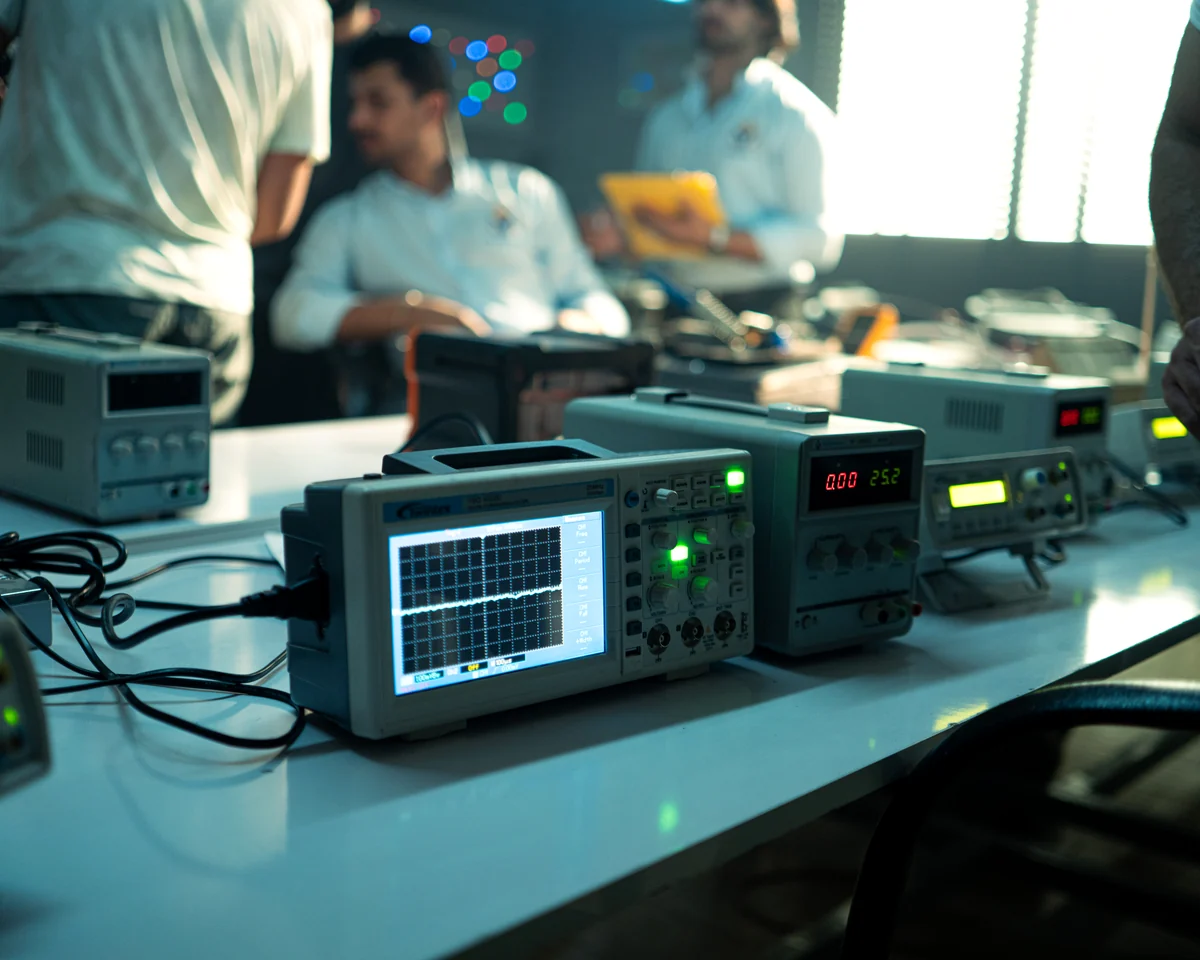
A human machine interface in aviation is the installed boundary through which a pilot sees aircraft information, enters commands, and confirms system response. For OEM engineers and procurement teams, the right hardware is not simply a touch screen or keypad; it is a controlled assembly matched to the pilot task, installation, and certification plan. Specify the intended function, viewing envelope, gloves, vibration, mass allocation, failure cues, connector retention, flammability basis, and evidence owner before freezing the stack. Custom HMI assemblies can cover the manufacturable front-panel boundary, but aircraft integration, safety assessment, software, and approval remain separate responsibilities.

A microwave oven membrane keypad should be specified as part of the installed control system, not as artwork attached late in development. It fits OEM appliances that need a low-profile, graphic-rich pressure interface, provided the overlay, circuit, key feel, adhesive, tail exit, housing seal, controller logic, and test plan are designed together. The critical inputs are key layout, steam and cleaner exposure, local panel temperature, display and backlight geometry, tail routing, enclosure construction, regulatory market, and production-intent sample approval. This is a custom OEM design guide, not consumer replacement or repair advice.

Human machine interface cybersecurity begins with a boundary decision: determine which access paths the front-panel hardware can remove, restrict, reveal, or monitor, then assign every remaining control to the HMI controller and the wider OT system. This applies to OEM engineers specifying displays, touch sensors, overlays, switch circuits, service ports, indicators, bezels, and enclosure interfaces. Hardware can obstruct physical access, expose tampering, and provide a dedicated signal path. It cannot authenticate a user, validate firmware, authorize a PLC command, encrypt traffic, or preserve an audit trail by itself. The decisive variables are physical access, service workflow, interface purpose, threat capability, indicator source, enclosure construction, and required response.
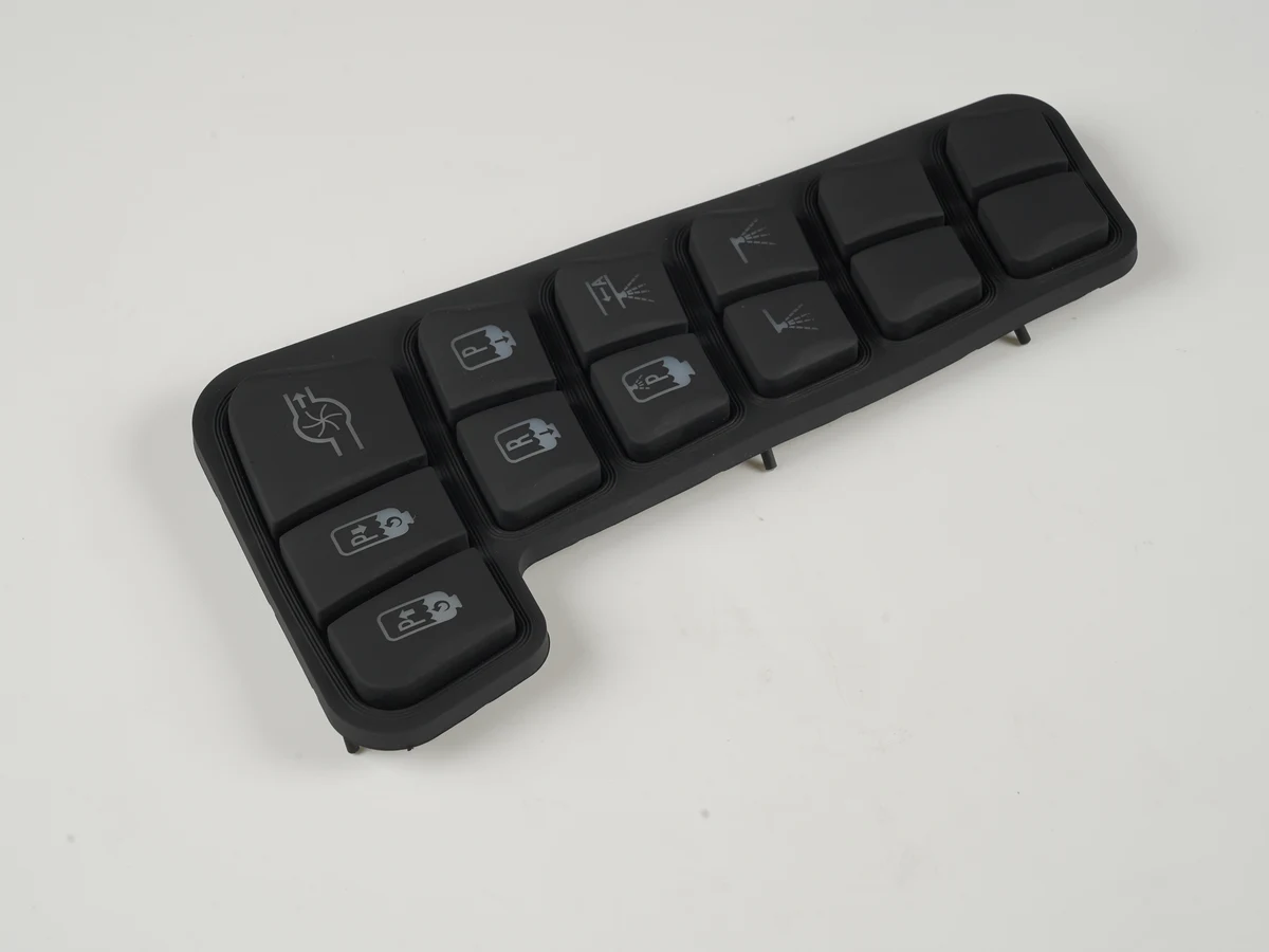
Rugged silicone rubber keypads for military equipment are custom-molded operator interfaces designed as part of a sealed electronic assembly—not drop-in parts that become “military grade” by material choice alone. They suit radios, vehicle controls, exposed panels and portable instruments when engineers define the force-displacement curve, enclosure seal, operating temperatures, fluids, legend wear, lighting, EMI bond path and PCB contact together. The right recommendation is configuration-specific: use silicone where tactile, gloved, low-profile input and geometric sealing are valuable, then qualify the production-equivalent keypad, PCB and enclosure against a tailored life-cycle profile.
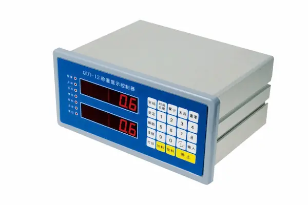
An HMI for oil and gas equipment should be specified as a front-panel system, not as a display chosen in isolation. The documented hazardous-location classification sets the first boundary. Sunlight, glove type, water, vibration, corrosion, ambient temperature, grounding and remote-service needs then determine the optical stack, input technology, seal geometry and enclosure interfaces. This guidance applies to OEM engineers, product designers, quality teams and technical buyers. It covers manufacturable HMI assemblies and their mechanical/electrical interfaces; the final-equipment manufacturer, site engineer and certification body retain responsibility for area classification, system approval and PLC/SCADA behavior.
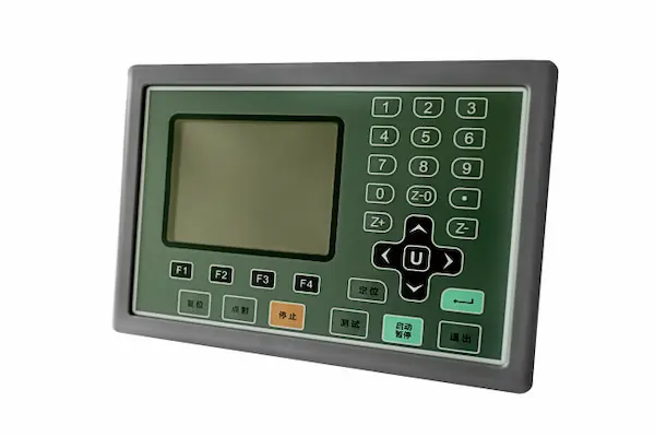
An HMI panel for water treatment should be specified as a sealed operator-interface assembly, not selected by screen size or a front-face IP label alone. This applies to OEM skids, local wastewater panels, outdoor pump stations, and water-reuse equipment. Start with the actual liquid, chemical, glove, light, temperature, cleaning, and service conditions. Then define the display, touch method, overlay, gasket, panel cutout, connector, enclosure, and corrosion interfaces as one boundary. JASPER's manufacturing scope covers that front-panel hardware; PLC/SCADA programming and process-control logic remain with the controls team.
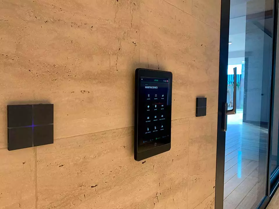
A smart-home capacitive touch panel should be specified as a complete interface stack, not selected by screen diagonal or faceplate appearance alone. For OEM engineers developing a KNX capacitive touch panel in the 4.3-inch class, the recommended path is to freeze the cover lens, sensor geometry, display, optical treatment, controller interface, wall-box envelope and validation conditions together. Custom capacitive touch panels suit sealed, low-profile controls with programmable icons. They are a poor default for safety-critical commands without an independent protective strategy, or for uncontrolled water exposure without defined false-touch and recovery criteria.
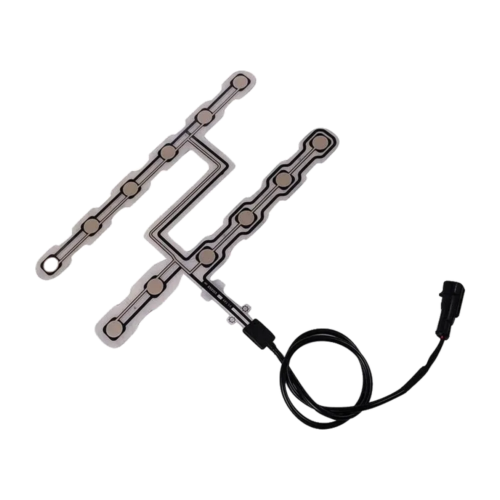
A dual-tension seat occupancy sensor is a project-specific flexible sensing component that provides either two decision thresholds or two observable channels to an occupant-classification system (OCS). Use it when one threshold cannot separate empty-seat preload from intended occupancy with adequate margin, or when two seat zones provide useful spatial evidence. The design must be released against the actual trim, foam, support, heating or ventilation layers, connector route, occupant cases, and environmental conditions. It is an input to classification—not a certified airbag decision. The OEM or system owner retains threshold logic, diagnostics, vehicle validation, and FMVSS No. 208 responsibility.
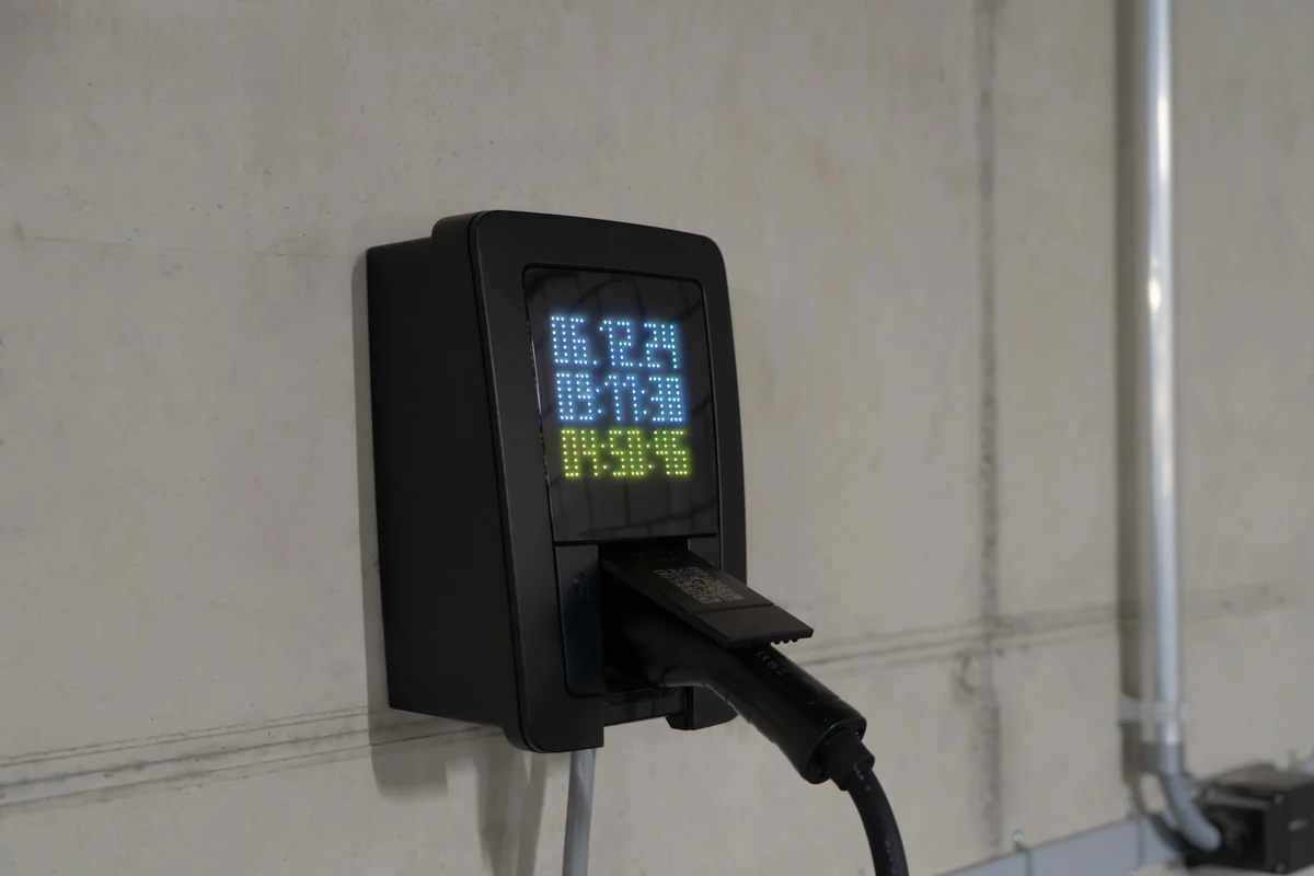
An EV charging station HMI panel is the complete user-facing hardware assembly, not merely an LCD. For public outdoor EVSE, specify the optical stack, touch or key input, cover and graphics, gasketed enclosure joint, payment-reader zone, electrical interfaces and service boundary as one system. The right construction depends on ambient light, solar and internal heat, rain or cleaning exposure, glove use, impact risk, accessibility, host architecture and replacement strategy. OEM teams should select targets from the charger’s installation and compliance plan, then validate a production-representative assembly. No single brightness, glass thickness or IP rating fits every charge station HMI panel.
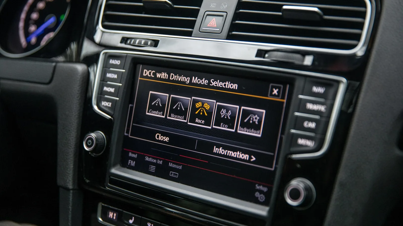
An automotive human-machine interface is the physical and electronic assembly through which a driver or passenger receives vehicle information and issues commands. For OEM and Tier-1 teams, the integration decision covers the display, touch sensor, cover lens or overlay, tactile controls, circuit, flex tail, connector, bracket, enclosure, grounding, and sealing interfaces. The right construction depends on vehicle function, viewing conditions, mounting location, touch-use case, environmental loads, EMC targets, and validation ownership. Treat these elements as one controlled stack. JASPER's manufacturing boundary is the front-panel and HMI hardware assembly; cockpit software, PLC/SCADA programming, and ADAS control algorithms remain outside that boundary.

A remote HMI is an operator interface whose display, touch input, or service access is separated from the controlled equipment by a network link. The sound hardware choice depends on where power is available, how much data must move, whether the operator can issue commands, what happens when the link fails, and how the antenna, display, touch sensor, gasket, enclosure, and local controls work together. Use wired Ethernet with local power when availability dominates, PoE when one standards-based cable can support the measured load, and wireless only after the RF path, cybersecurity owner, latency behavior, and loss-of-link state are defined.

A USB capacitive touch panel is a projected-capacitive sensor and controller assembly that reports touch coordinates to a host through USB, usually as a Human Interface Device (HID). It is not a video interface: HDMI, DisplayPort, LVDS, eDP, or MIPI DSI carries the image separately. USB is usually the right external interface when an OEM needs standard PC-class host connectivity without a custom touch driver. Direct I2C or SPI is often better inside a closed embedded product. The decision depends on controller compatibility, HID firmware ownership, coordinate mapping, connector and cable design, power states, electromagnetic compatibility, and validation on every target host.
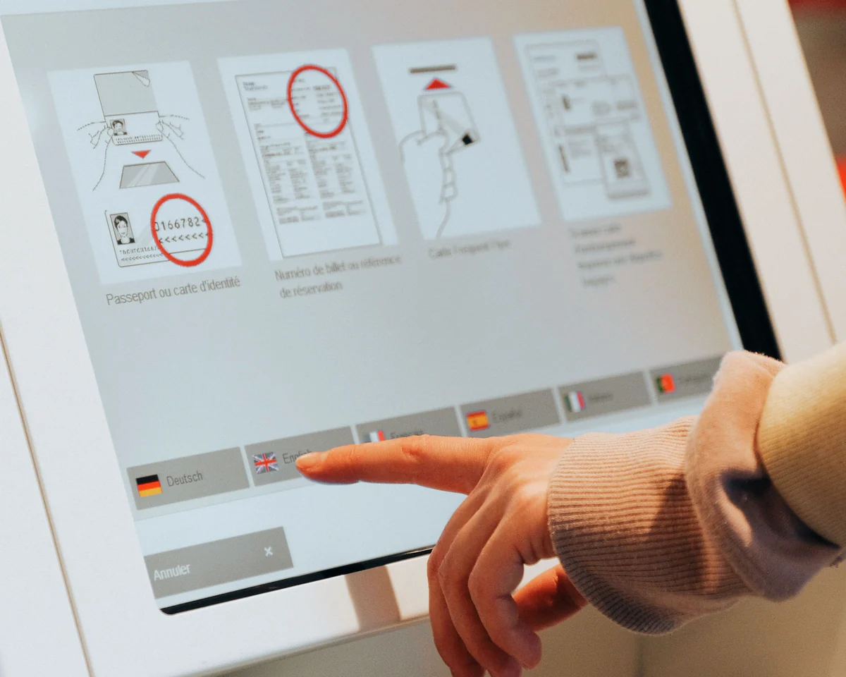
Human factors HMI requirements turn operator capabilities, tasks, protective equipment and working conditions into testable front-panel specifications. They apply to the display, touch sensor, overlay, physical controls, circuit, bezel and enclosure interface—not only to screen graphics. Define the intended users and critical tasks first; then specify reach, sightlines, character angle, touch-target geometry, actuation force, feedback, contrast, grouping, error recovery and workload acceptance. Verify those requirements on the assembled panel with representative operators, gloves, ambient light, contamination and machine motion. PLC/SCADA programming remains outside JASPER’s manufacturing scope, but the hardware must give the control system a usable, unambiguous physical interface.
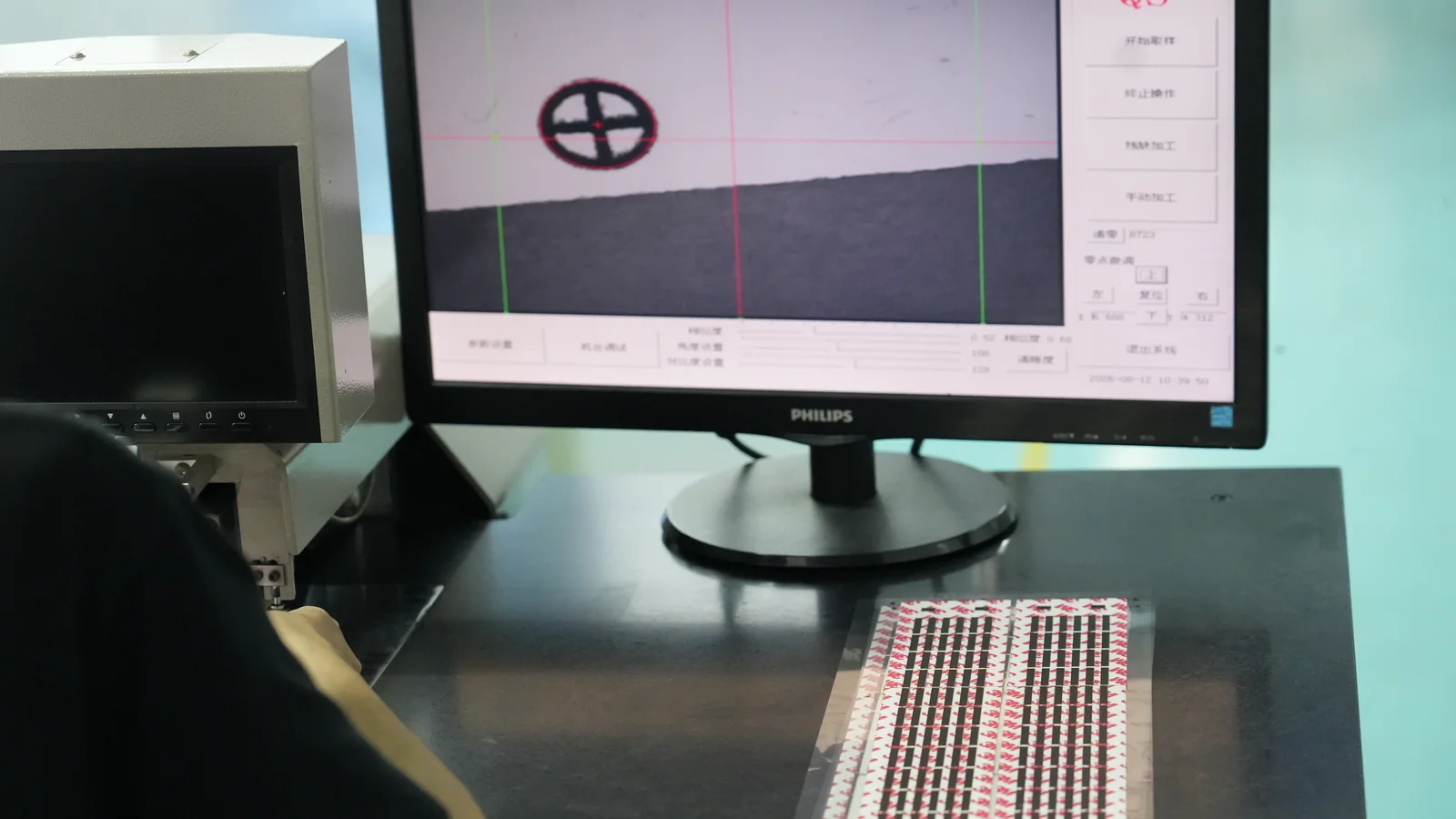
Industrial HMI standards are not one certificate or one design rule. OEM teams should screen an HMI by destination market, finished-equipment category, installation environment, safety function and approval owner before specifying the panel stack. ISA-101 and IEC 63303 address HMI-system design and lifecycle; they do not certify a touchscreen, overlay or finished machine. Hardware evidence must instead follow the applicable product-safety, enclosure, EMC, hazardous-location and material requirements. The practical rule is simple: define the end use first, then require evidence for the tested configuration and preserve the finished-equipment manufacturer’s approval boundary.
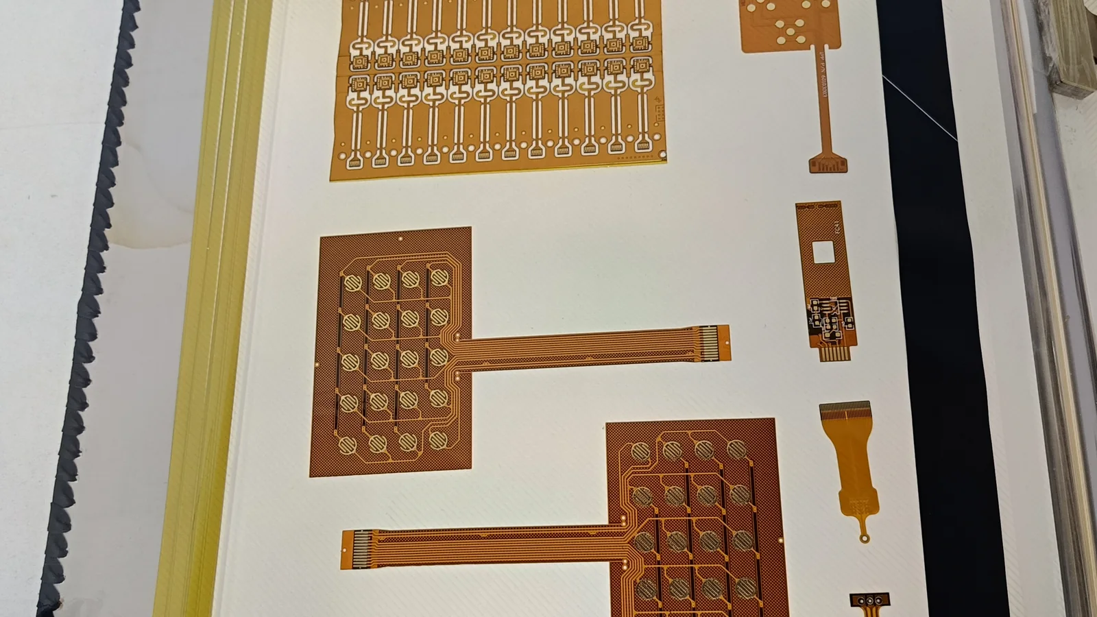
HMI communications are not selected by protocol name alone. An OEM must match the HMI runtime to the controller’s data model, then specify the physical layer, connector, isolation, cable, enclosure boundary and validation conditions. Ethernet suits new networked panels; RS-485 fits a simple Modbus serial bus; CAN/CANopen fits mobile machinery; and BACnet belongs primarily in building automation. Length, noise, ground-potential difference, washdown, motion and hazardous classification can change the answer. This guide covers that hardware boundary—not PLC or SCADA programming.

A harsh environment HMI is a front-panel hardware assembly designed to remain legible, operable and electrically stable under defined mechanical, climatic, chemical and electromagnetic loads. OEM teams should specify it from the field exposure profile—not from a “rugged,” IP or NEMA label alone. The practical method is to allocate each load to the cover, bond, touch sensor, display, carrier, seal, grounding path, ports and enclosure interface, then test a production-representative assembly in its intended mounting. For custom HMI assemblies , the decisive variables are impact, vibration, ingress, UV, chemicals, temperature, ambient light, gloves, grounding and service access. PLC and SCADA programming sit outside this hardware boundary.
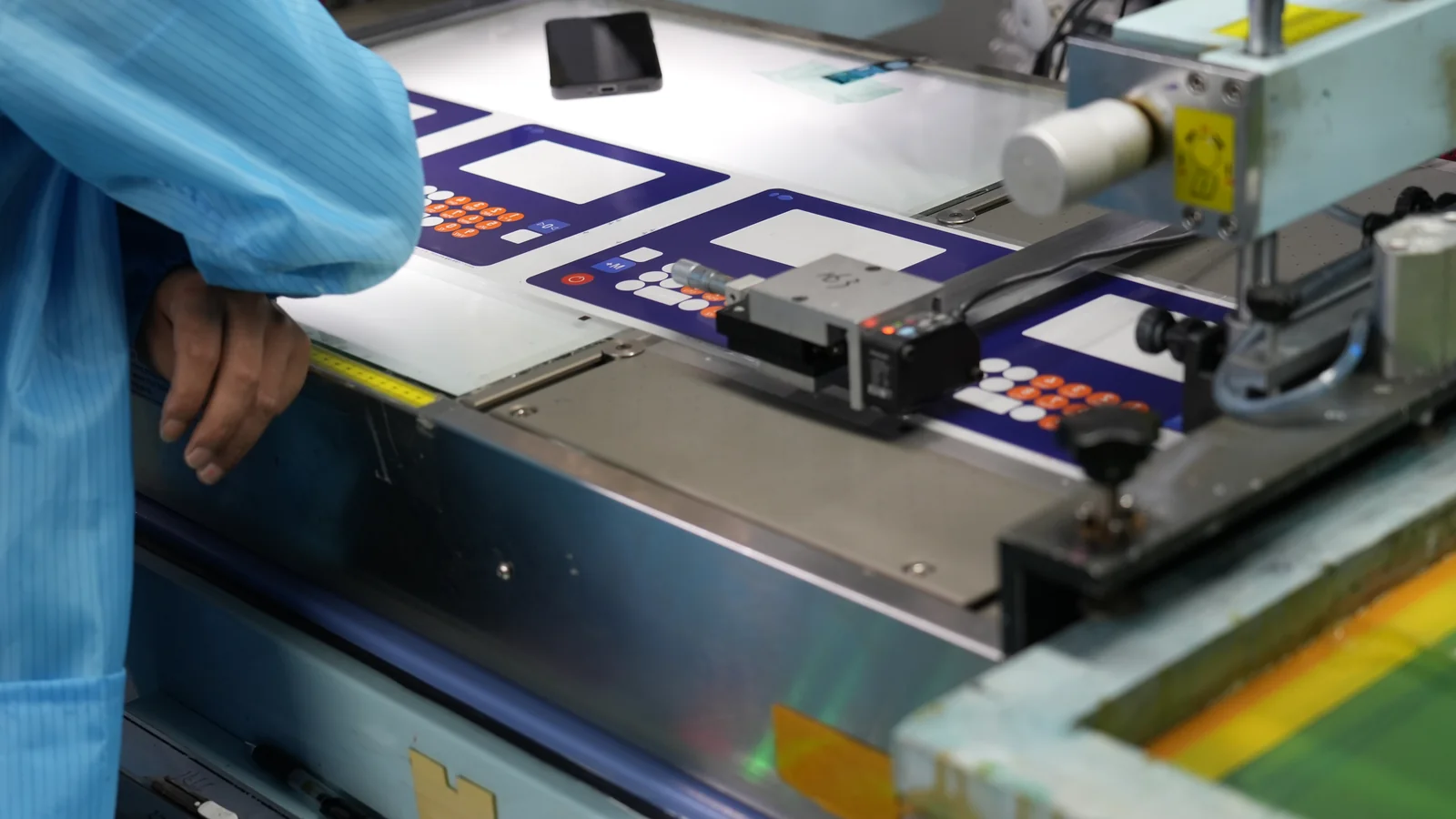
HMI development for OEM equipment converts user tasks and operating conditions into a controlled physical interface: the front panel, display, touch or key input, circuit, connector, seal and enclosure boundary. The recommended sequence is requirements, stack architecture, interface freeze, representative prototypes, validation, change control and production release. It applies to OEM engineers, designers, quality teams and technical buyers. The controlling variables are users, tasks, environment, input method, optical needs, mechanical stack, electrical interfaces and acceptance criteria. PLC/SCADA programming remains outside the hardware manufacturer’s scope.
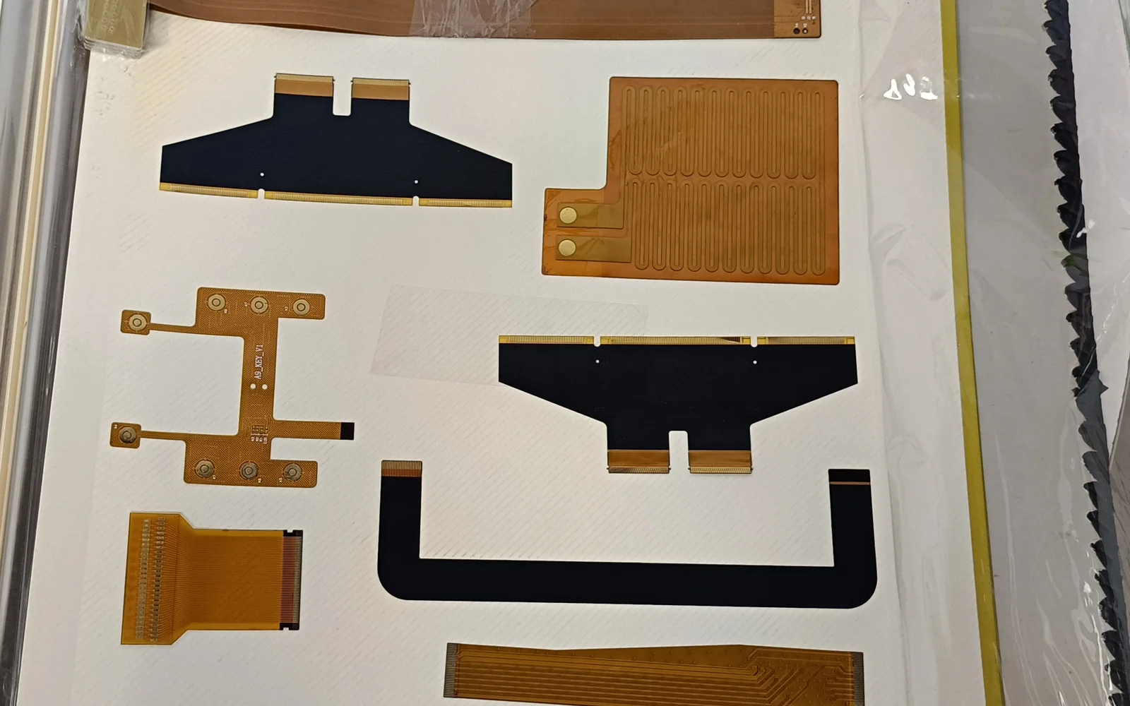
HMI automation hardware is the physical operator interface between a person and an industrial controller: the display, touch or key input, front overlay, circuit, processor, connectors, seals and mounting features that present machine state and carry authorized commands. OEM teams should define that architecture from operator tasks and failure response, then freeze the viewing, input, environment, PLC interface, enclosure and service requirements. This guide applies to machine builders and panel designers. It covers the manufacturable front-panel assembly and its electrical and mechanical boundaries; PLC logic, SCADA programming and control-system validation remain with the OEM or controls integrator.
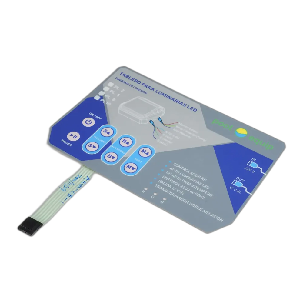
An ATEX HMI must be specified as part of a complete explosion-protected equipment design, not as a display selected by IP rating or screen size. This decision applies to OEM engineers, compliance teams and technical buyers placing an operator interface in a classified gas or dust area. Start with the jurisdiction, signed area classification, substance group, required equipment category or protection level, ambient range and maximum surface-temperature limit. Then define the certified assembly boundary, enclosure method, sealing, grounding, heat path, cable entries and permitted changes. A custom front panel can support that design, but it does not inherit ATEX approval from one certified component.
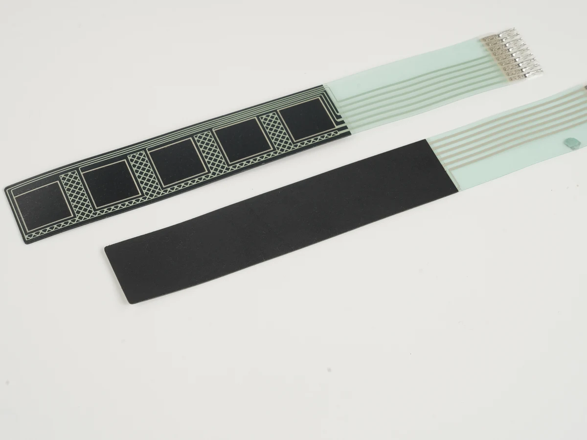
A capacitive touch foil is a flexible sensor layer that places projected-capacitive electrodes behind a nonconductive touch surface. It is useful when an OEM needs a thin, lightweight or statically curved interface, but it is not automatically the best substitute for a rigid PCAP sensor. Choose the architecture only after fixing the cover lens, active area, electrode technology, adhesive, tail path, controller, display stack, curvature and operating environment. For optically critical flat displays, a rigid sensor may offer easier dimensional control. For keys or hidden controls, a printed sensor film may be simpler than a transparent XY touchscreen. These decisions belong in the system design for capacitive touch panels , not in the film drawing alone.
A 32 inch PCAP touchscreen should be selected as an installed sensing system, not as a glass size. OEM teams need to freeze the active area, aspect ratio, electrode material and pitch, controller channel architecture, cover/display stack, edge routing, enclosure datums, interface and operating states together. Large format is practical when the controller and sensor preserve touch margin at the worst location and the bonded assembly remains flat, clean and mechanically unloaded. If those inputs are unknown, a quoted diagonal and interface are not enough to approve the design.
An HMI PC is an operator-interface system in which a display, touch input, computing platform, power path and machine interfaces are engineered as one hardware architecture. A dedicated HMI panel is usually the best fit for a fixed machine task and controlled runtime. An integrated panel PC fits local Windows or Linux applications and compact installation. A separate embedded computer plus touch display fits projects that prioritize independent upgrades, thermal isolation or field replacement. The choice applies to OEM engineering, quality and procurement teams; display stack, compute load, input/output, enclosure exposure, service strategy and supplier ownership matter more than the product label.
An LCD capacitive touchscreen is a system-level assembly, not an LCD with a touch sheet added at the end. OEM teams should release the cover lens, projected-capacitive sensor, bond or controlled air gap, TFT LCD, flex circuits, controller, grounding and enclosure as one stack. Use perimeter air bonding when rework and replaceable displays matter and the optical environment tolerates extra interfaces. Use full optical bonding when reflection, parallax, contamination control or a thin rigid stack justifies the tighter process. In either case, validate the installed unit with final firmware, cables, power supplies, bezel, gloves, moisture states and environmental loads. Component datasheets alone cannot establish finished-product performance.
High-performance HMI hardware is a front-panel assembly engineered so the intended operator can see machine state, recognize an abnormal condition, choose the correct control, and confirm the result under the specified lighting, contamination, glove, and viewing conditions. It applies to OEM teams integrating displays, touch sensors, overlays, switches, indicators, circuits, adhesives, seals, connectors, and enclosures. The practical recommendation is to specify the complete response path, then validate the assembled panel—not isolated components. For custom HMI assemblies , the decisive variables are visibility, information hierarchy, input method, feedback, response timing, environmental exposure, mechanical stack-up, and degraded-state behavior.
PLC and HMI integration is the engineered boundary between the controller that executes machine logic and the operator hardware that displays state and returns supervisory commands. For an OEM, a shared protocol is necessary but not sufficient. The design must freeze exact device models, power, electrical layer, driver and data map, connectors, grounding and isolation, display/touch stack, mounting seal, environment, and validation owner. Treat custom HMI assemblies as documented, replaceable hardware subsystems. Choose a combined PLC-HMI only when its smaller footprint outweighs the coupled service life, thermal load, and replacement path.
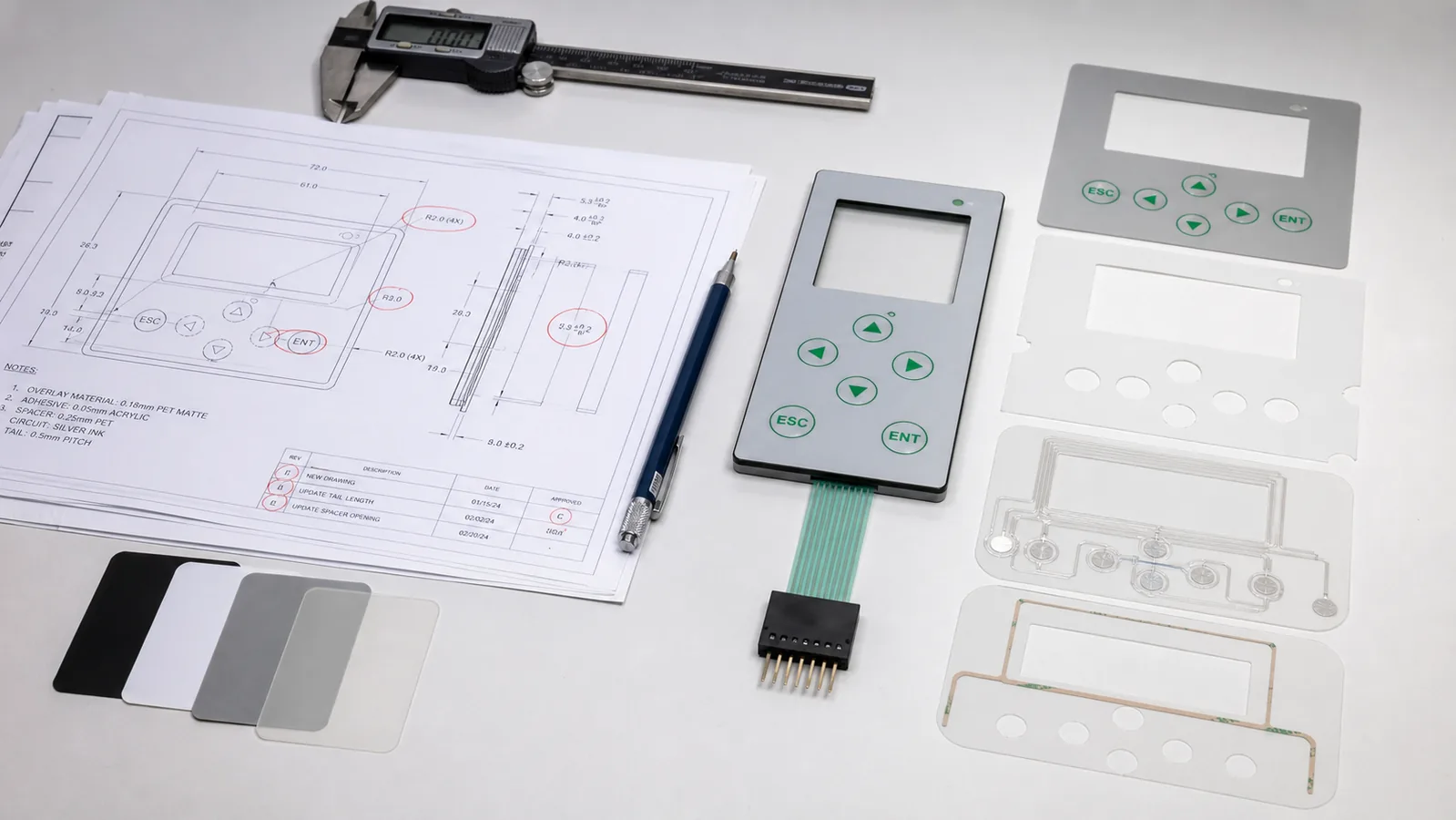
Review nine places where a complete-looking drawing can still leave the operator, material stack, adhesive, datums, tactile dome, tail, connector, sealing path, lighting, or production-intent sample undefined.
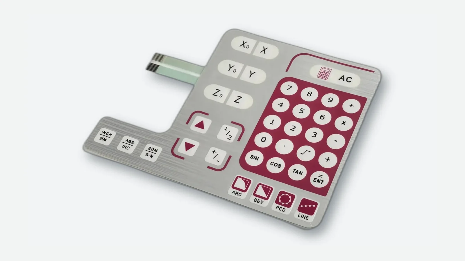
Membrane switch design guide covering stack, circuit, force, tail, connector, sealing, and sample approval—9 criteria plus drawing checklists for OEM teams.
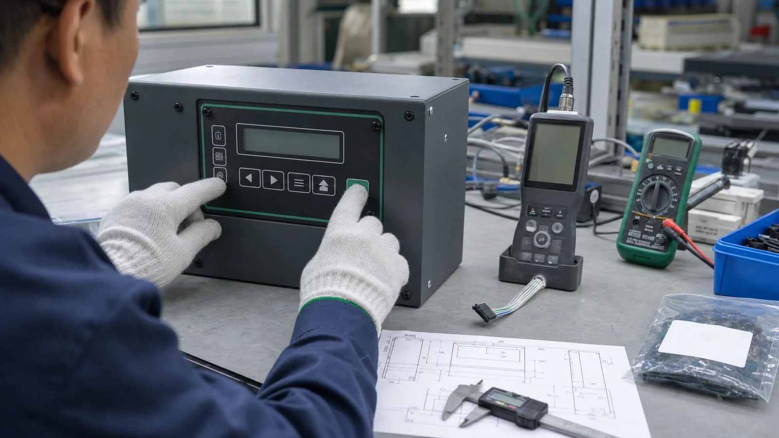
Use this membrane switch RFQ checklist to package drawings, quantities, environment notes, and acceptance checks so supplier quotes stay comparable.

How do membrane switches work? Trace pressure from overlay and spacer contact through circuit, tail, and connector to the host controller—tactile vs non-tactile.
Buyer guide to membrane switch materials by layer and operating exposure: polyester and polycarbonate overlays, hard coats, conductive inks, spacers, domes, and adhesive materials matched to enclosure substrates.
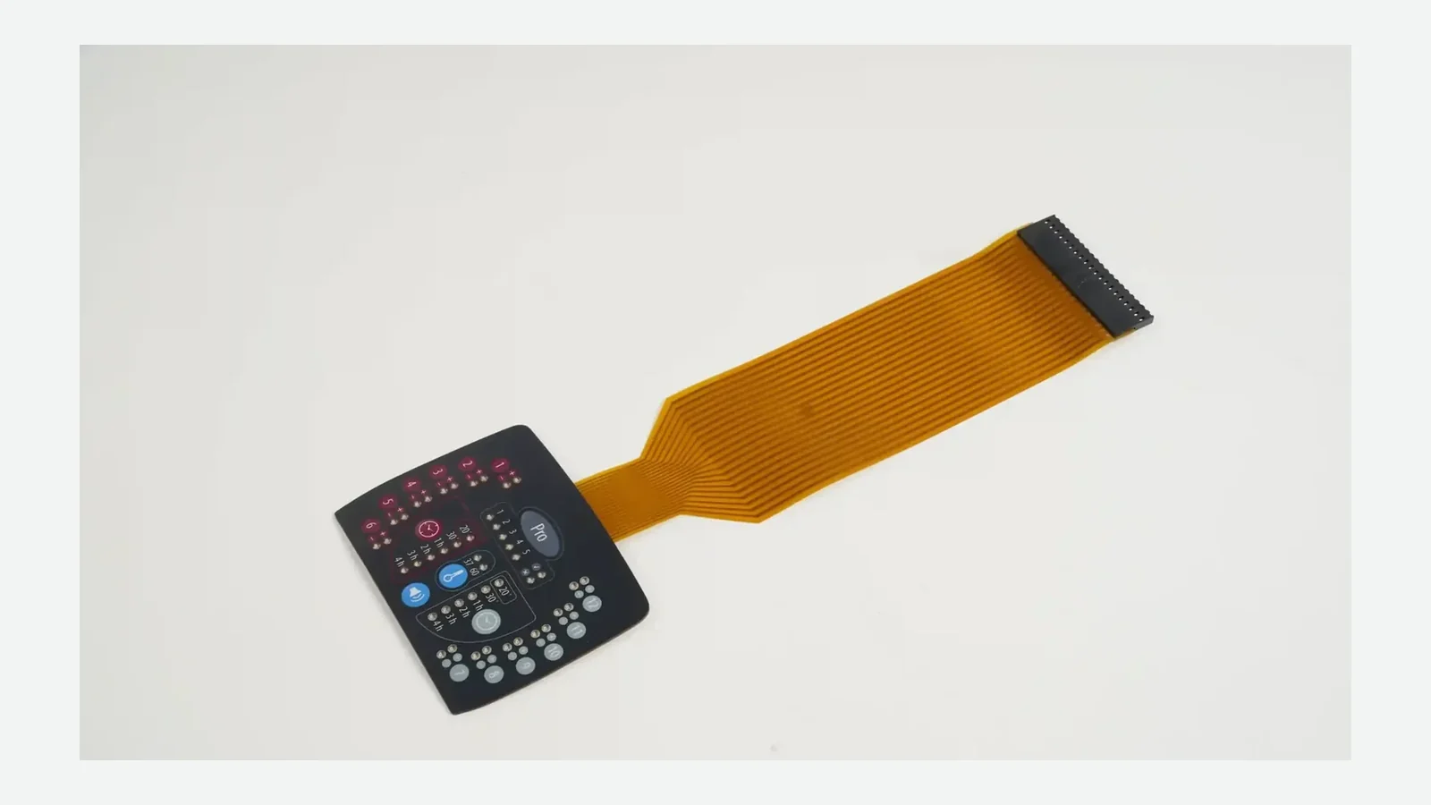
Membrane switch layers explained: stack-up diagram, base components, domes, shields, vents, windows, adhesives, IEC 60529 limits, and sample checks for OEM engineers.
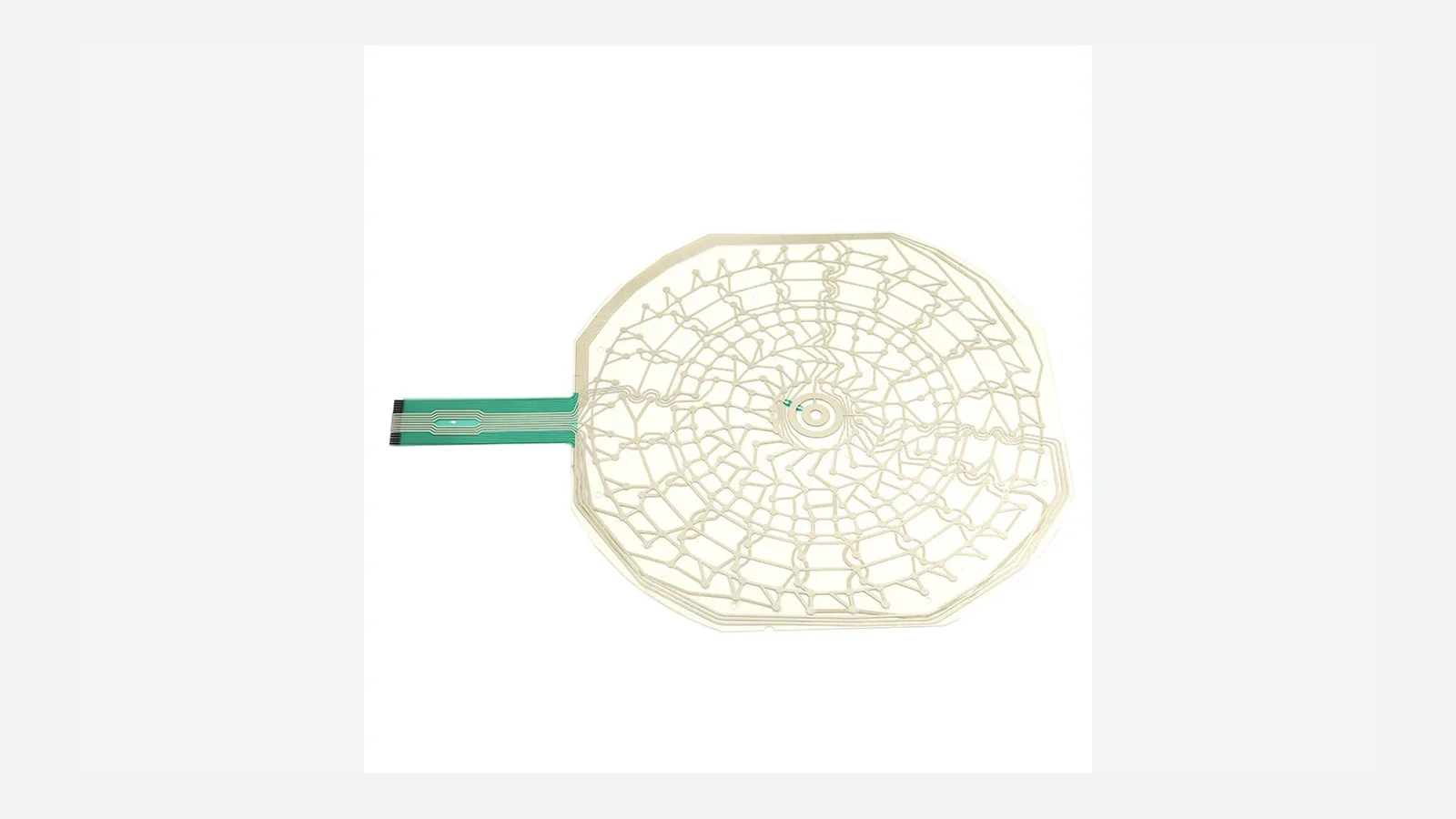
Engineering guide to membrane switch circuit design covering matrix vs common bus, printed PET circuits, FPC and PCB options, LED nets, shielding, pinout freeze, and electrical test planning before artwork release.
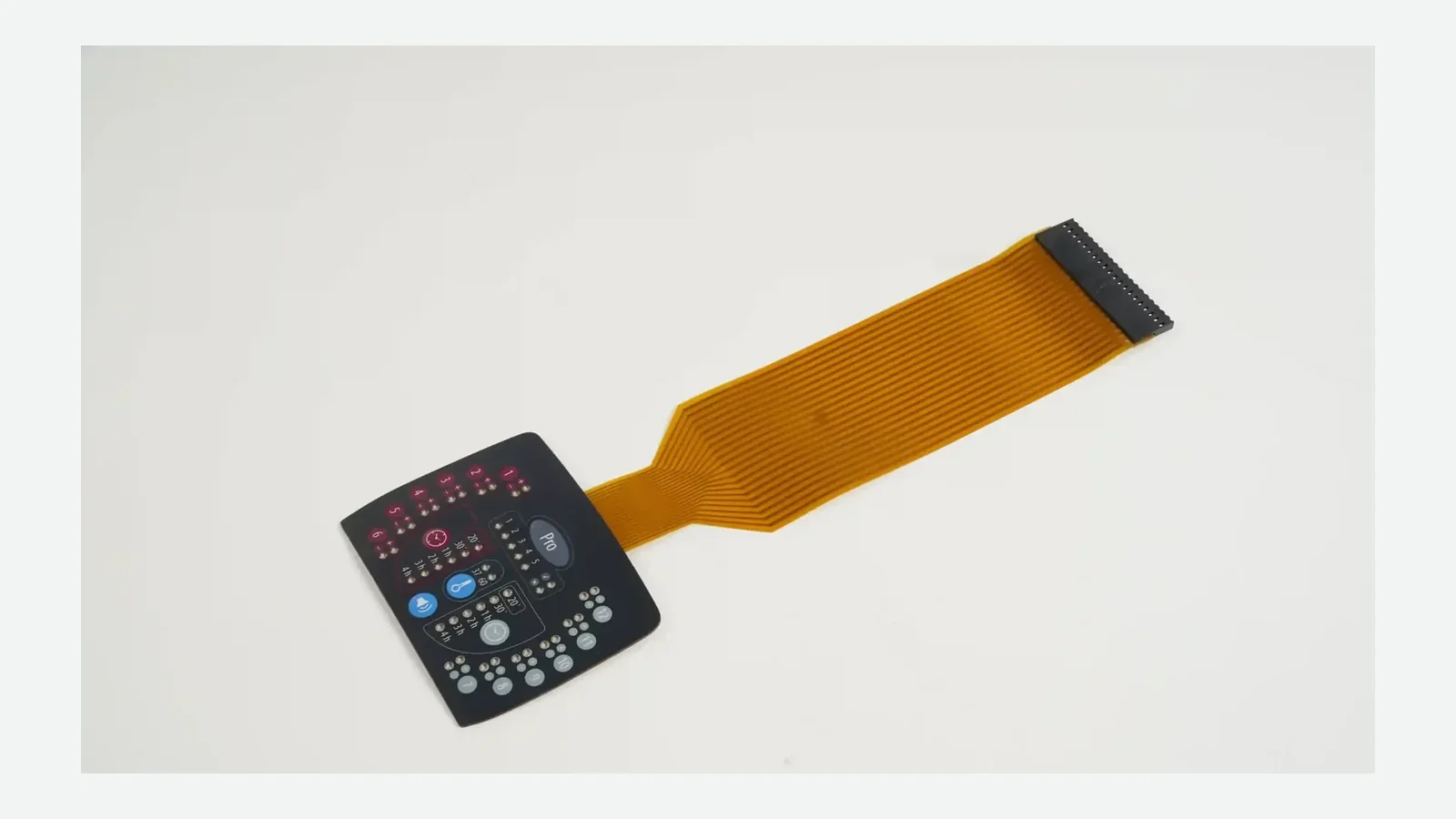
Specify membrane switch connector pitch, contact side, stiffener, tail exit, and flexible tail bend radius before sampling—with a 9-point checklist for OEM engineers.
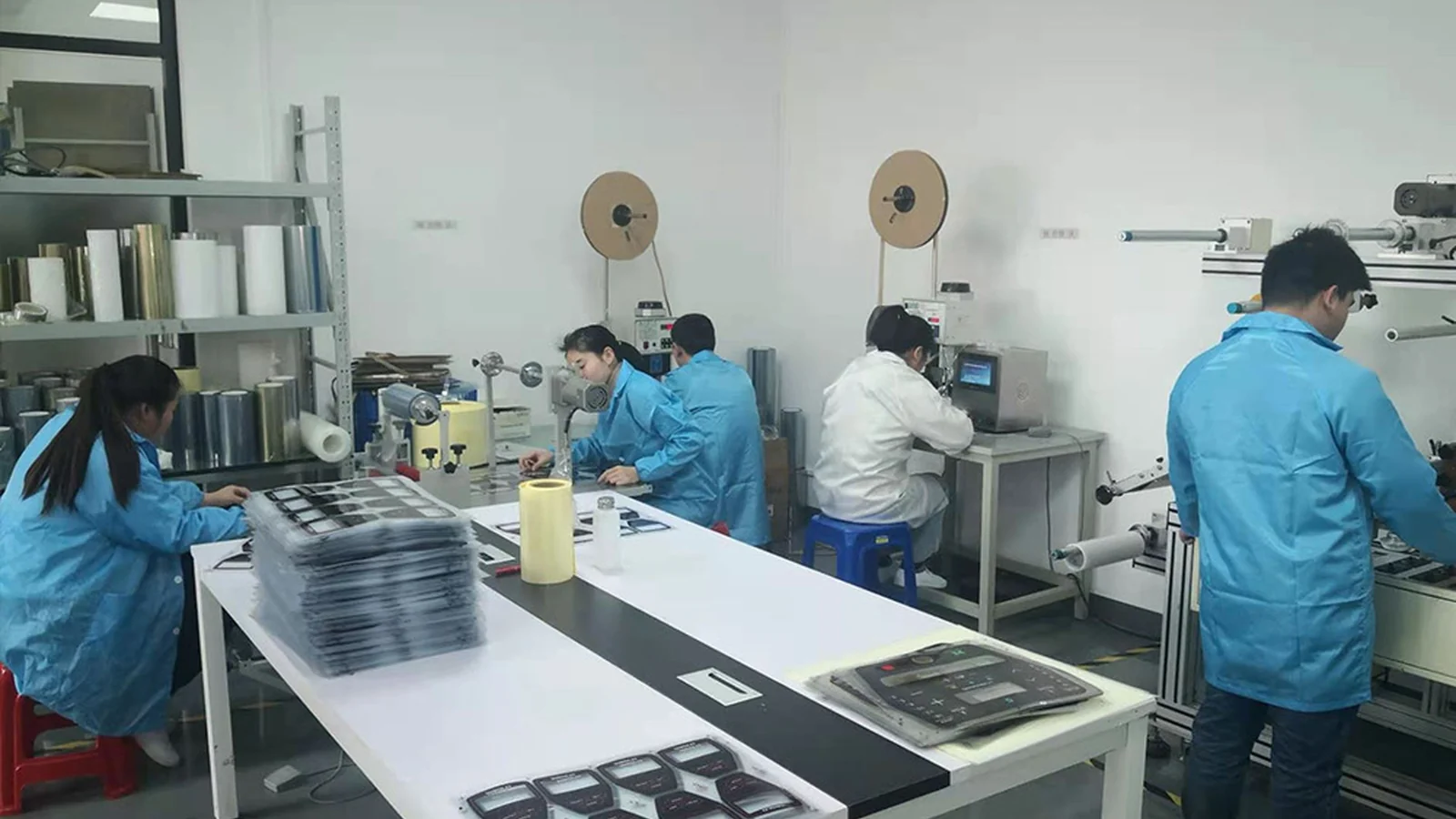
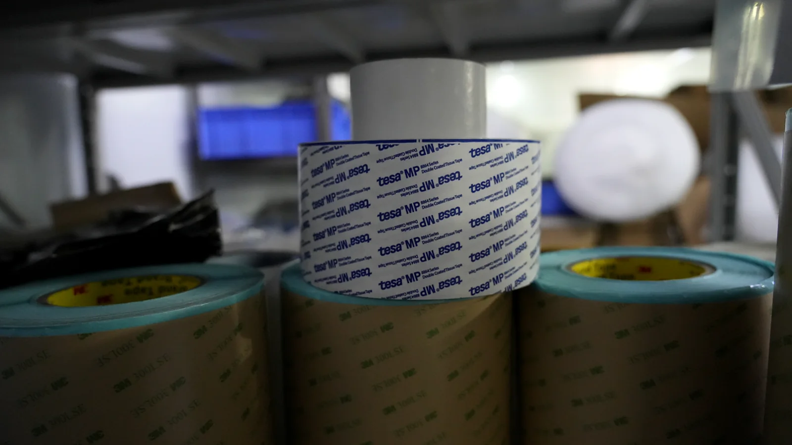
Membrane switch adhesive selection by surface energy, texture, edge land, temperature, and dwell. 9 criteria, 3M examples, sample checklist.
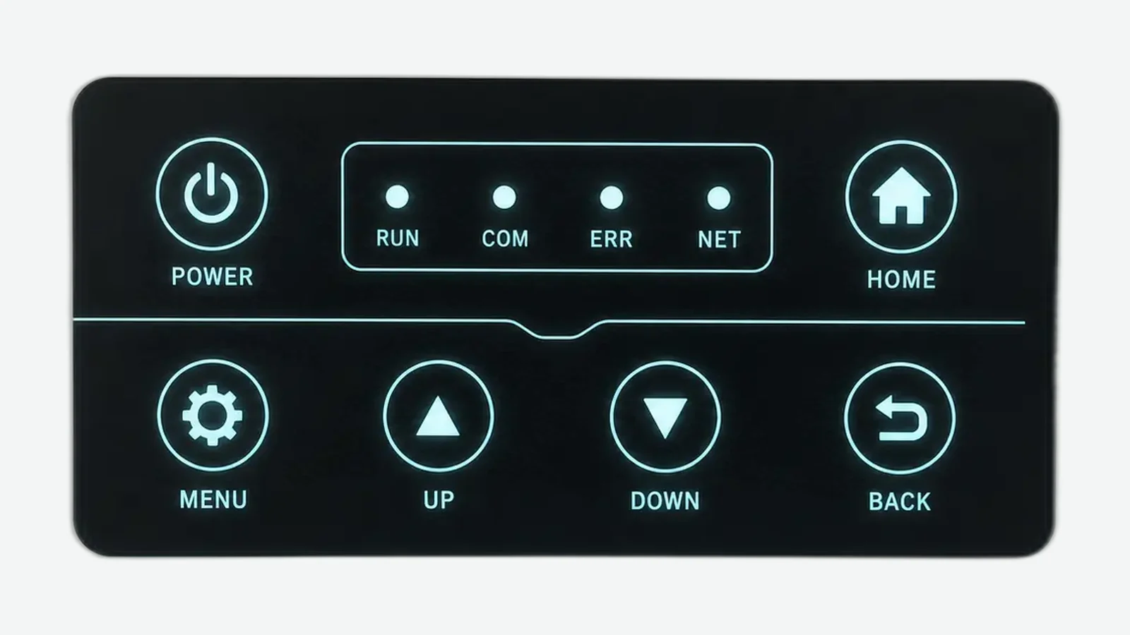
Buyer guide to membrane switch backlighting: compare discrete LED, light guide film, and electroluminescent constructions by brightness, uniformity, thickness, power, masking, and sample approval.
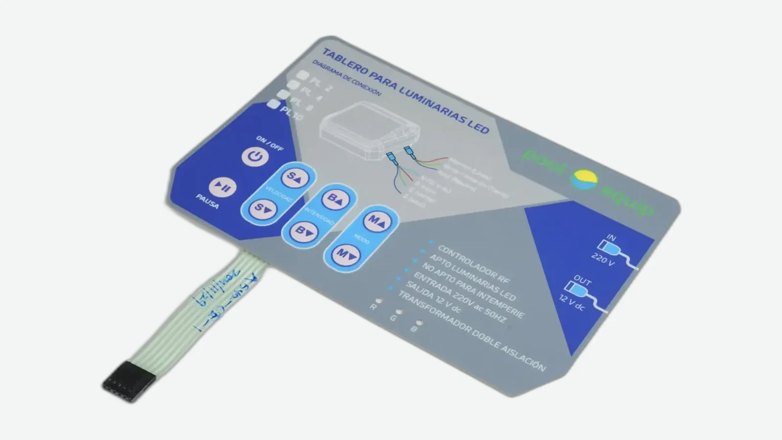
Compare IP65 vs IP67 membrane switch design under IEC 60529: jet versus immersion tests, dual-rating rules, six assembly seal paths, and validation checklist for OEM sealed keypads.

Buyer guide to membrane switch cost factors, tooling cost, inspection, samples, volume, packaging, and change control so OEM quotations stay construction-matched.
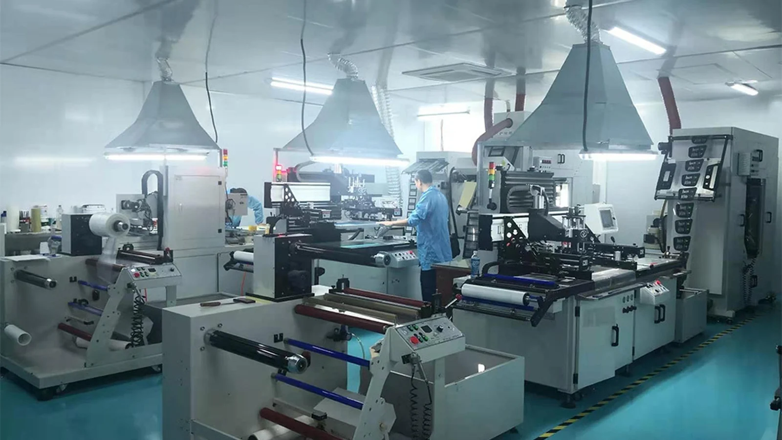
How to choose a membrane switch manufacturer: 10-point supplier evaluation, scorecard, sample matrix, and release blockers before tooling freeze.
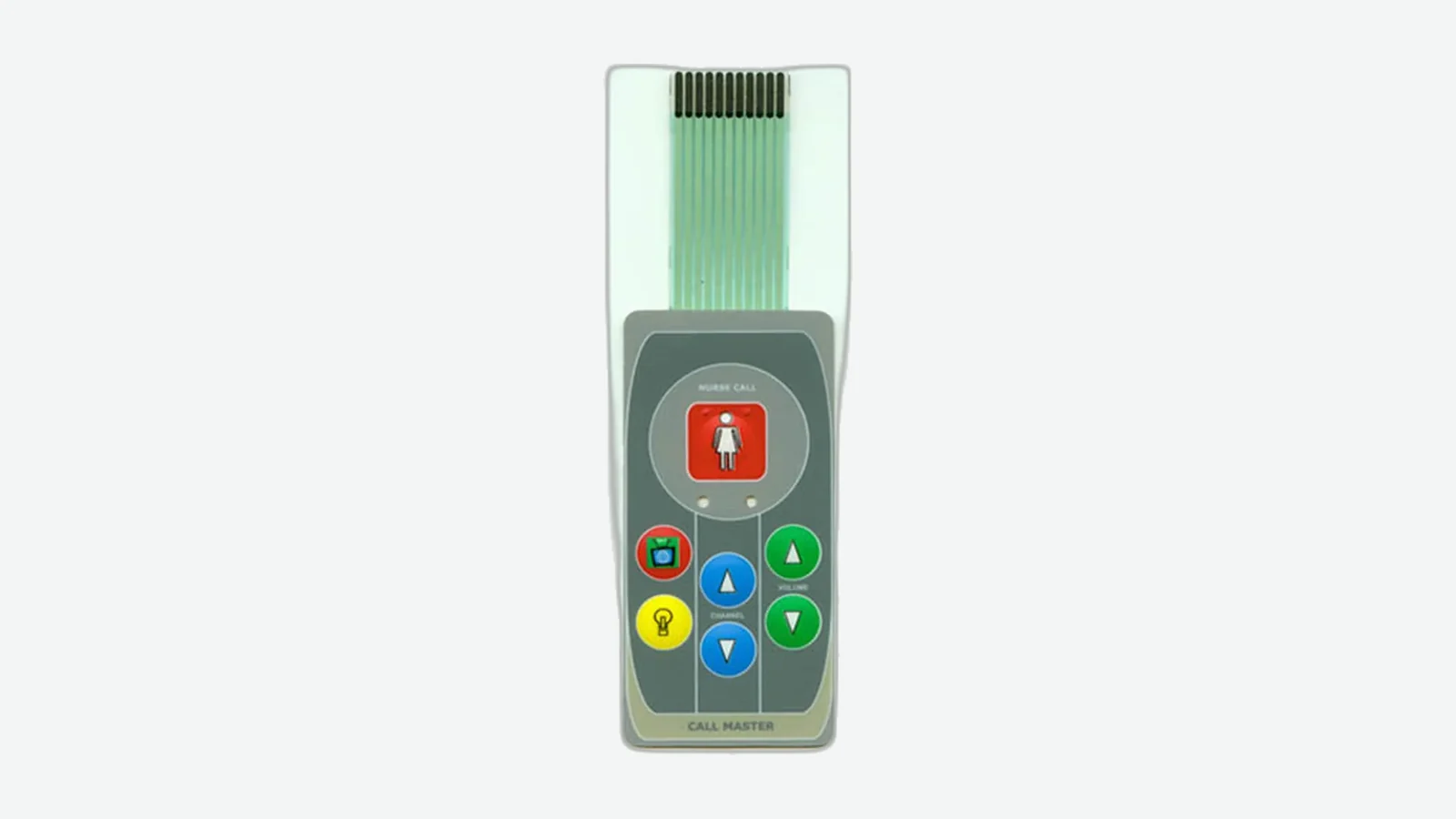
Tactile vs non tactile membrane switch comparison covering metal dome vs flat contact, force, travel, noise, gloves, cleaning, mixed zones, and sample-approval criteria for OEM HMI panels.
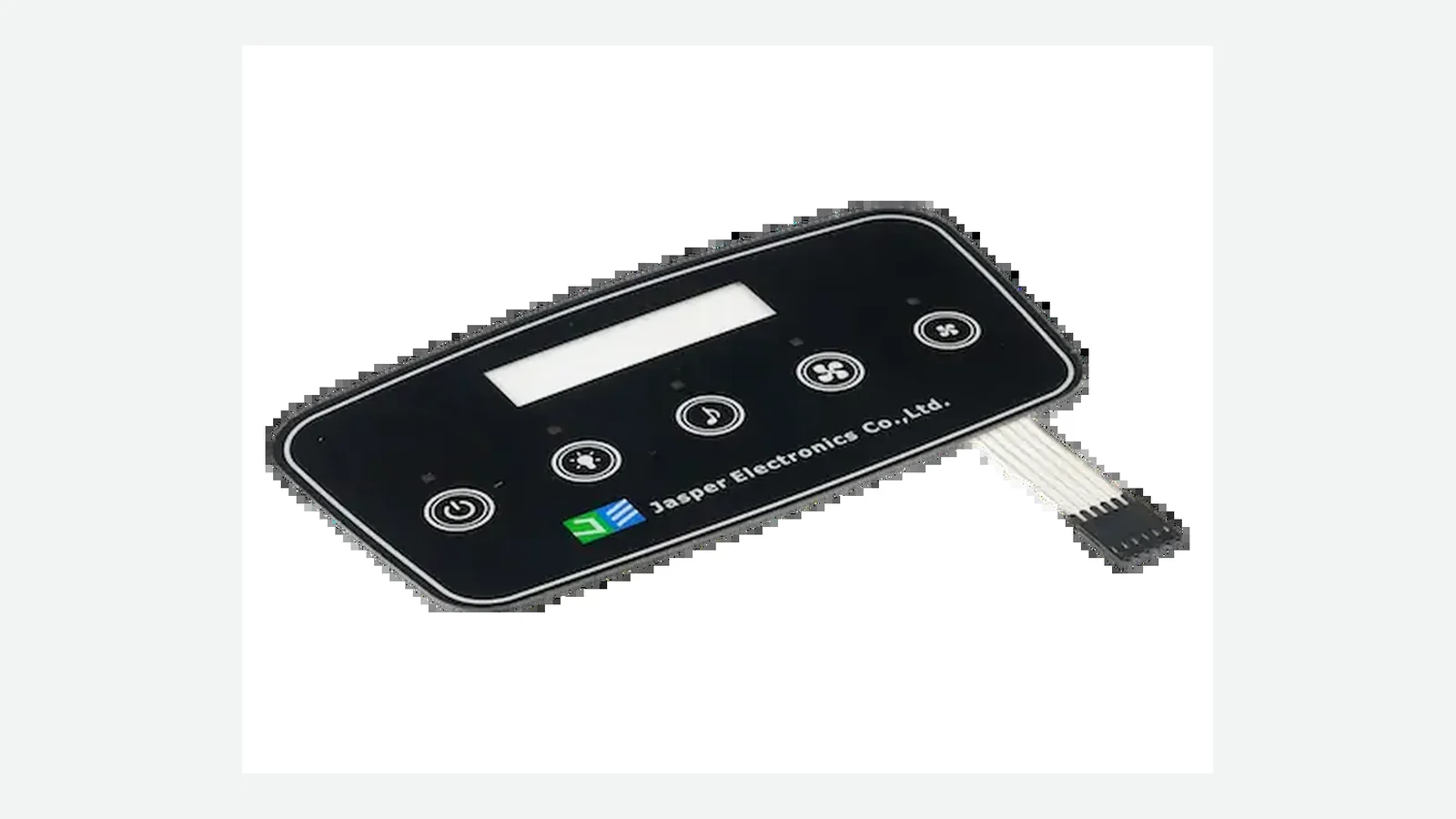
Membrane switch vs mechanical switch for OEM control panels: profile, sealing, feedback, serviceability, hybrid layouts, and a pre-RFQ decision matrix.
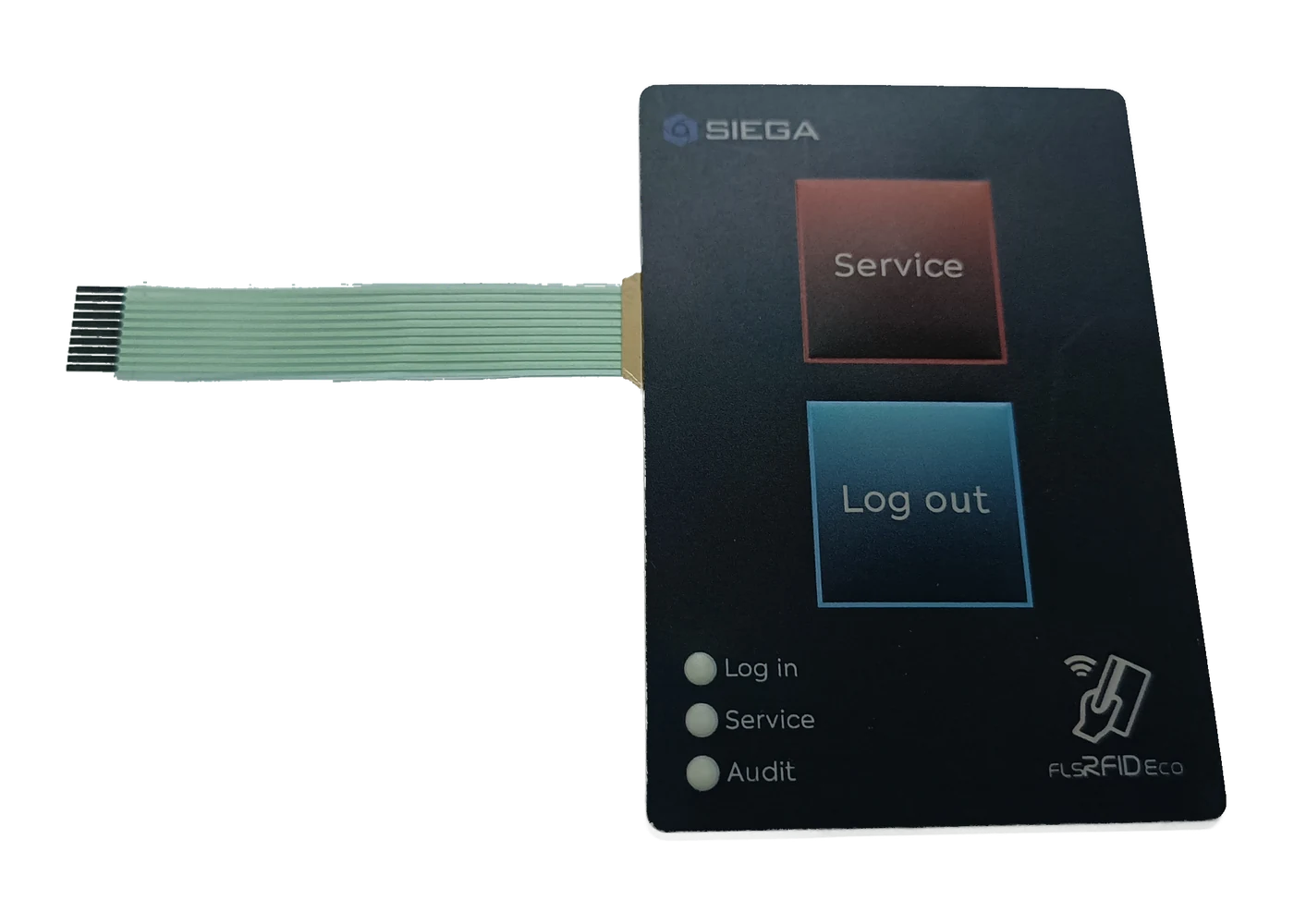
Build one measurable datum chain across overlay, circuit, tail, enclosure, windows, and acceptance evidence before tooling and sample release.
Membrane switch prototype approval checklist: what a production-intent first sample must prove on fit, feel, electrical, sealing, lighting, and FAI docs.
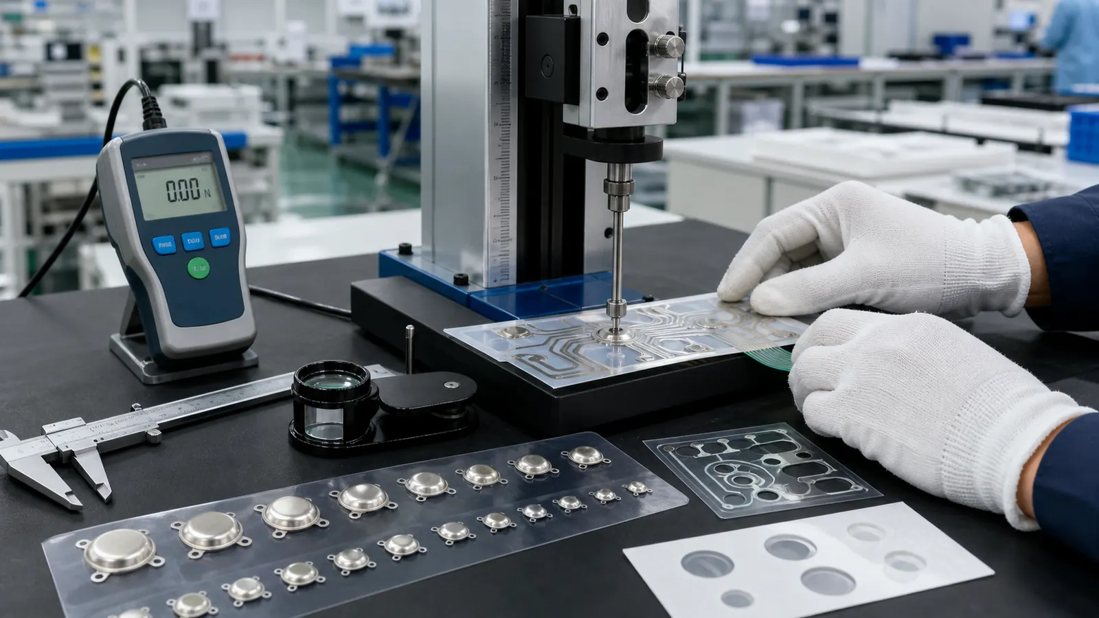
Metal dome selection guide for membrane switches: compare force, snap ratio, size, venting, travel, and full-stack samples before approval.

Non tactile membrane switch design: compare flat contact patterns, spacer openings, vent paths, support lands, and key-force validation.
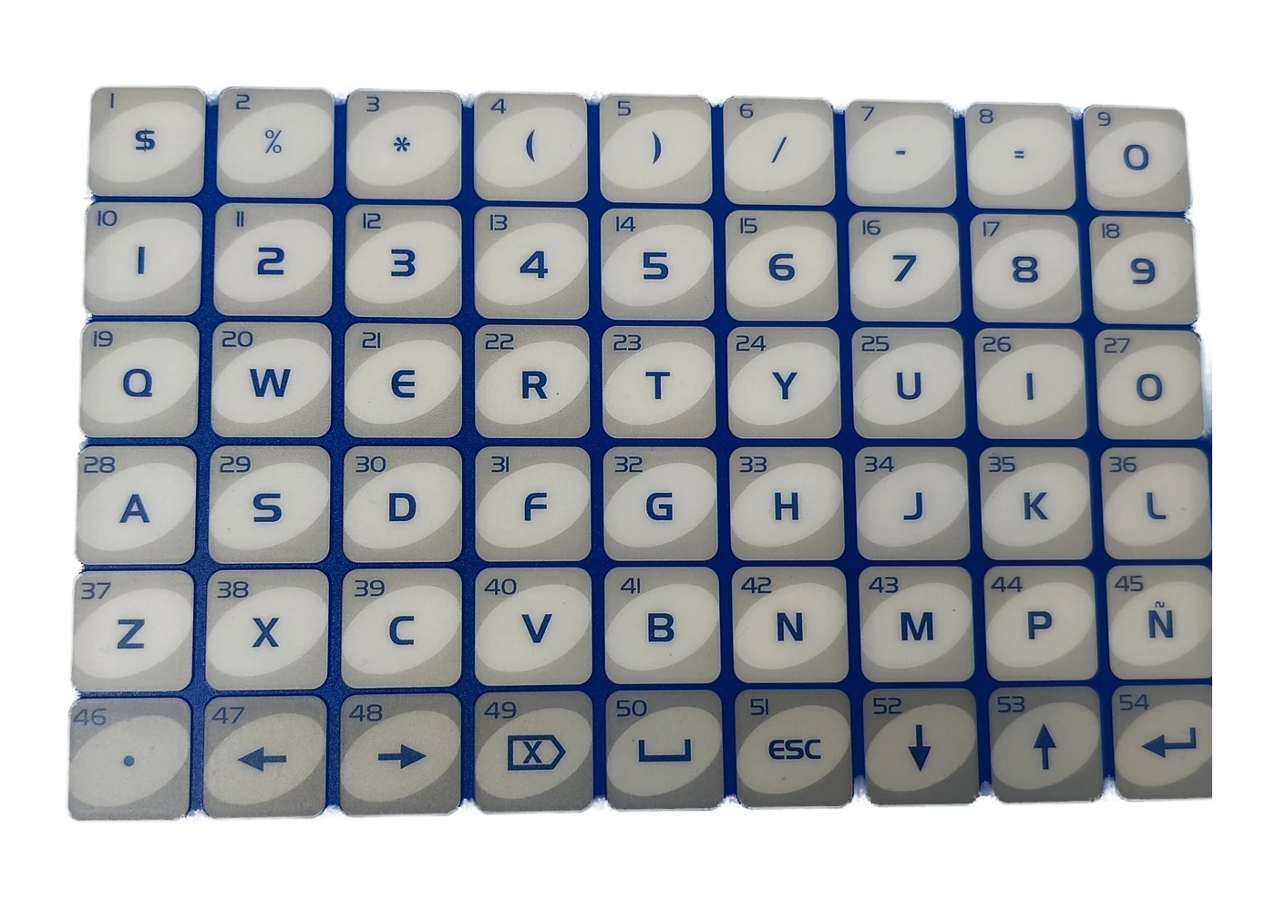
Set key spacing, legends, grouping, tactile cues, and sample checks from the real operator, task, mounting angle, and cleaning conditions.
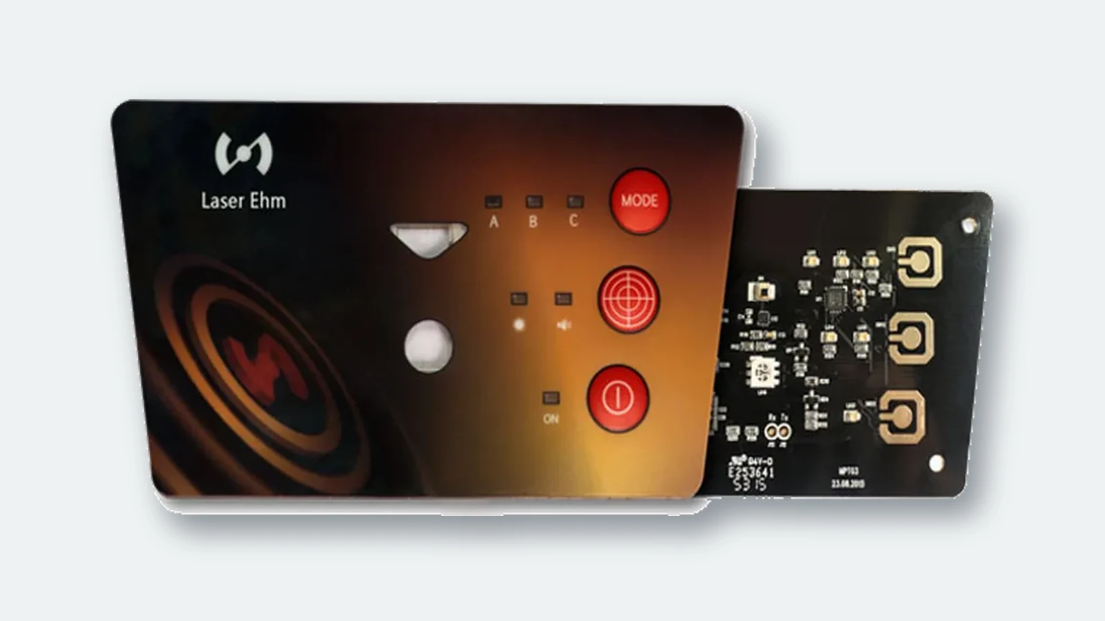
Coordinate bezels, windows, mounting, seal land, fasteners, cable routing, and service access against one controlled enclosure drawing.
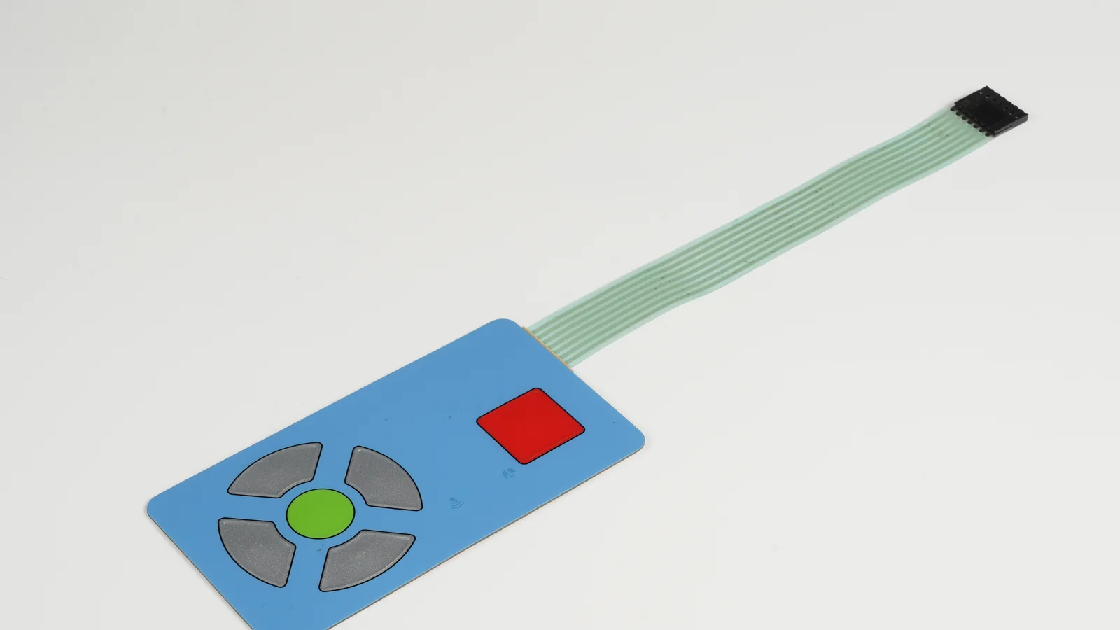
Coordinate operator targets, tactile elements, routing, datums, venting, enclosure features, and production-intent evidence before compact-key tooling.
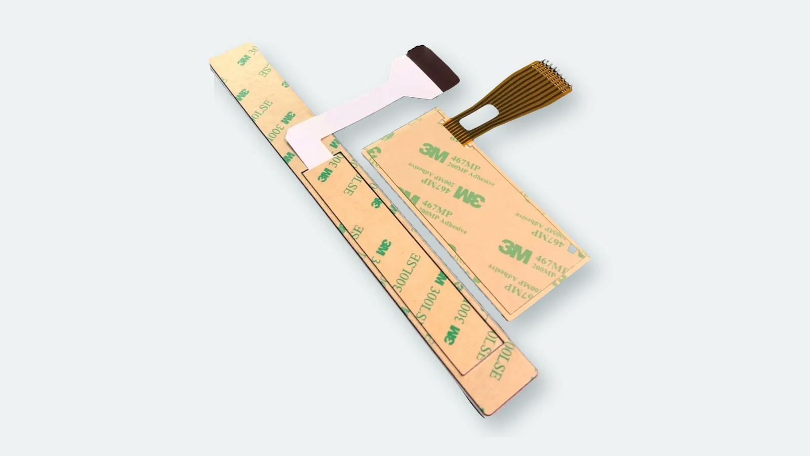
Map edges, windows, vents, tails, connectors, enclosure joints, and the evidence needed before approving an IP claim.
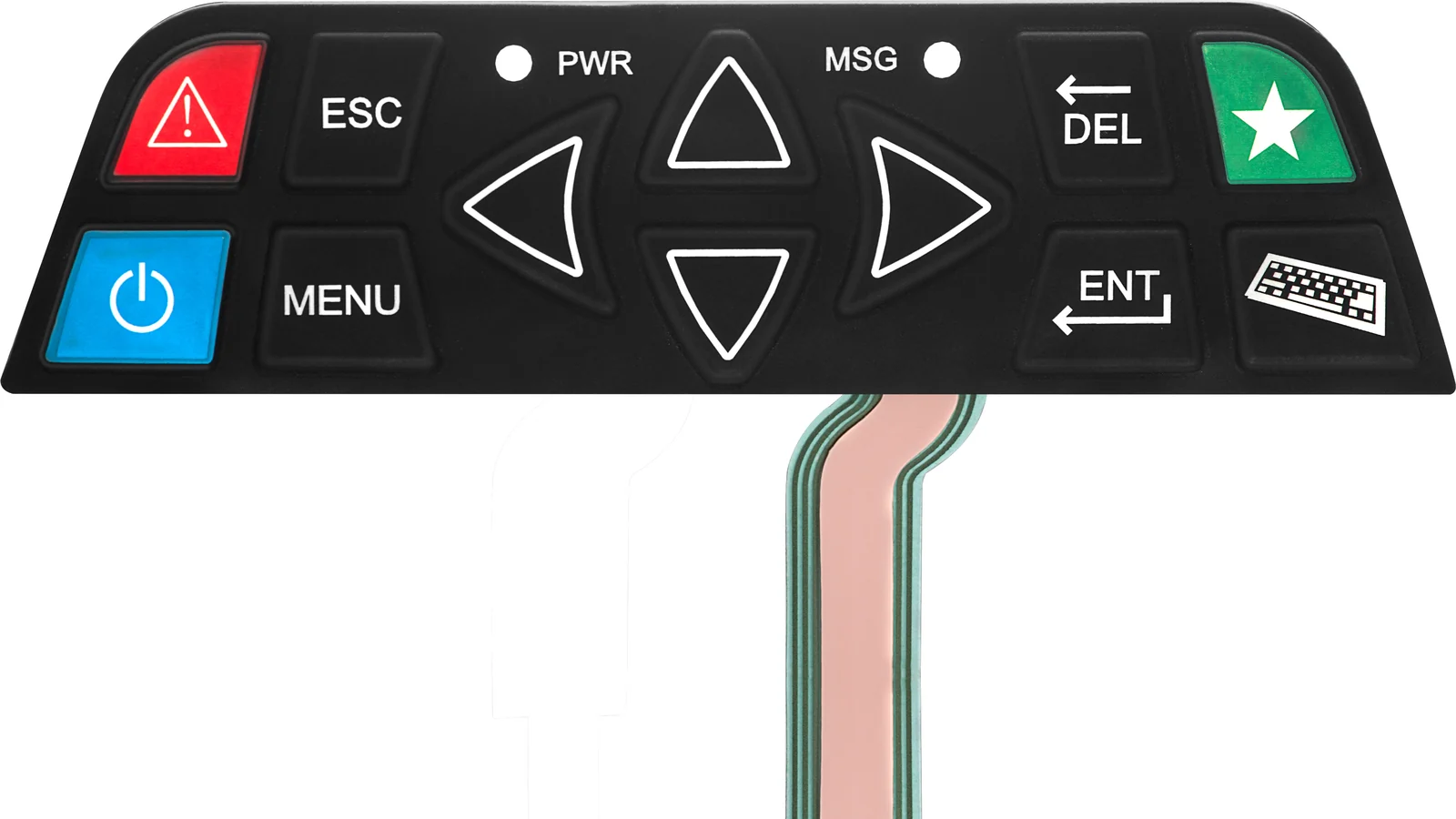
Connect controller limits and named LED data to branch routing, pocket geometry, optical masking, and powered first-article evidence.
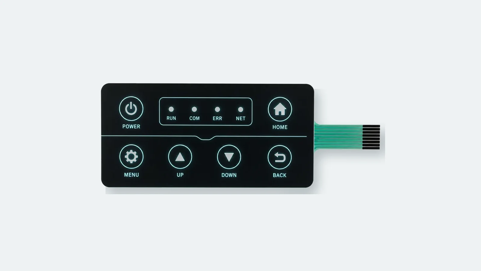
Control LED coupling, extraction, masking, enclosure effects, and luminance measurement before approving an LGF membrane-switch sample.
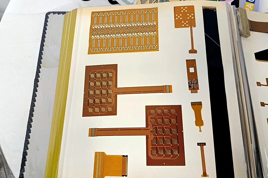
Compare rigid PCB, copper FPC, and printed PET by routing, resistance, bend path, component attach, connector, cost, and validation evidence.
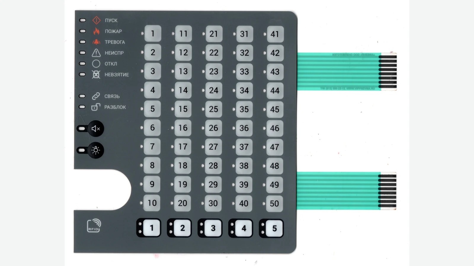
Set the bend zone from the finished tail stack, installation path, strain relief, and connector access instead of one generic radius.
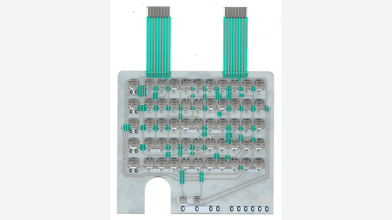
Choose printed, foil, or transparent shielding and define the grounding path, tail route, enclosure joint, and equipment-level EMC tests.
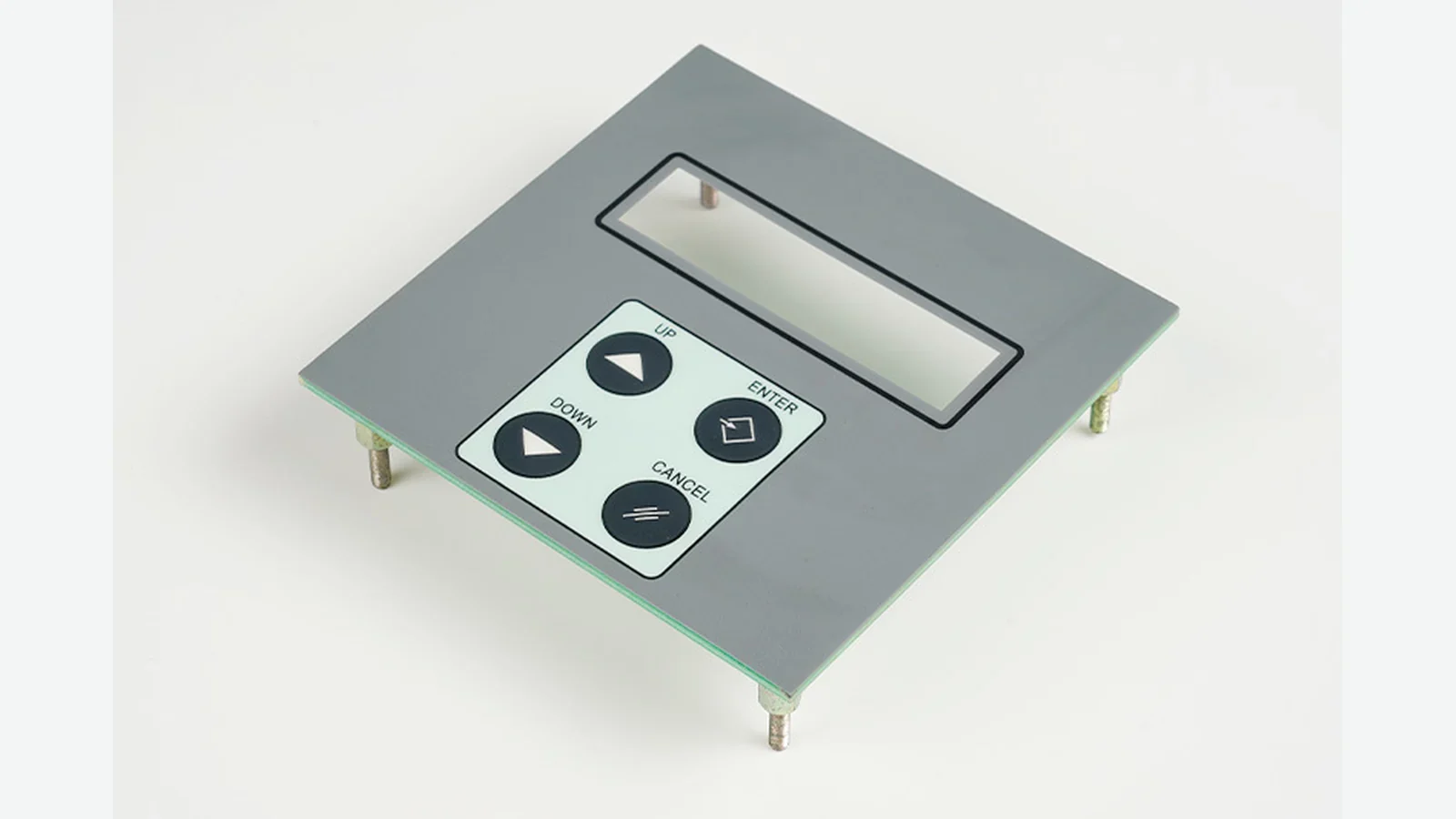
Compare graphic overlay vs membrane switch function, layers, drawings, tests, and replacement scope with 8 engineering tables for OEM interface design.
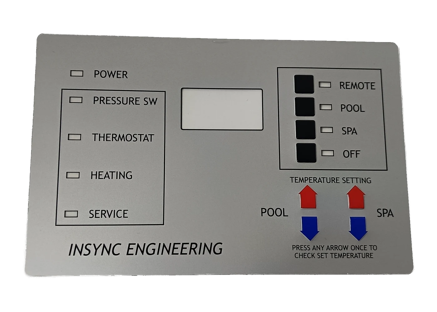
Define the overlay boundary through film, subsurface print, windows, embossing, adhesive, housing, and finished-assembly validation.
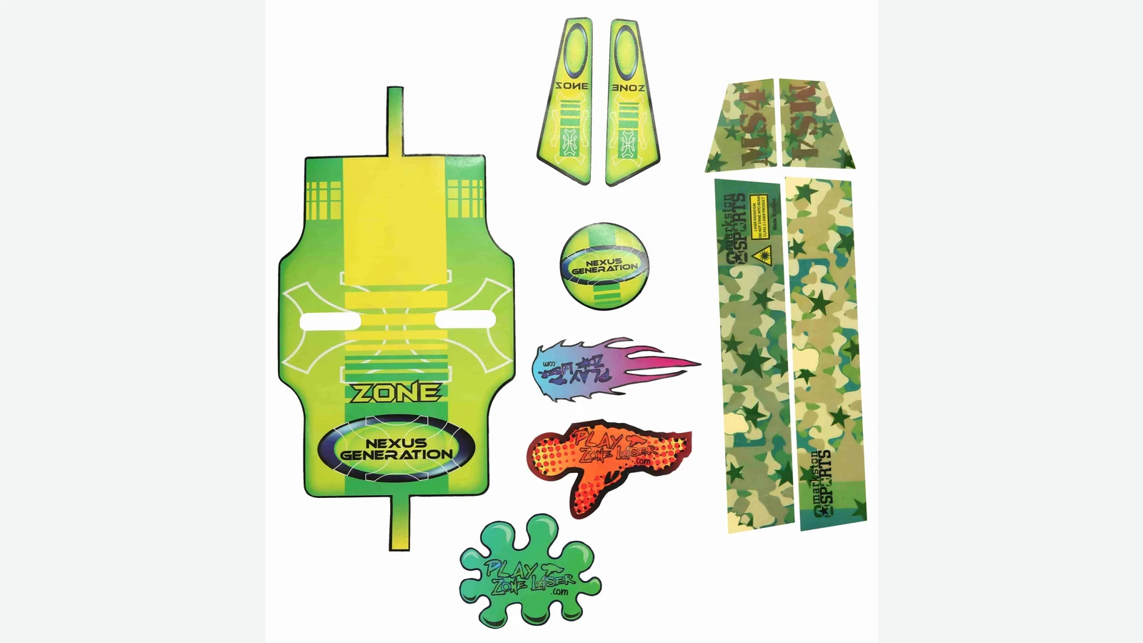
Compare named PET and PC constructions by flexing, forming, optics, chemicals, UV exposure, hardcoat, thickness, and assembled testing.
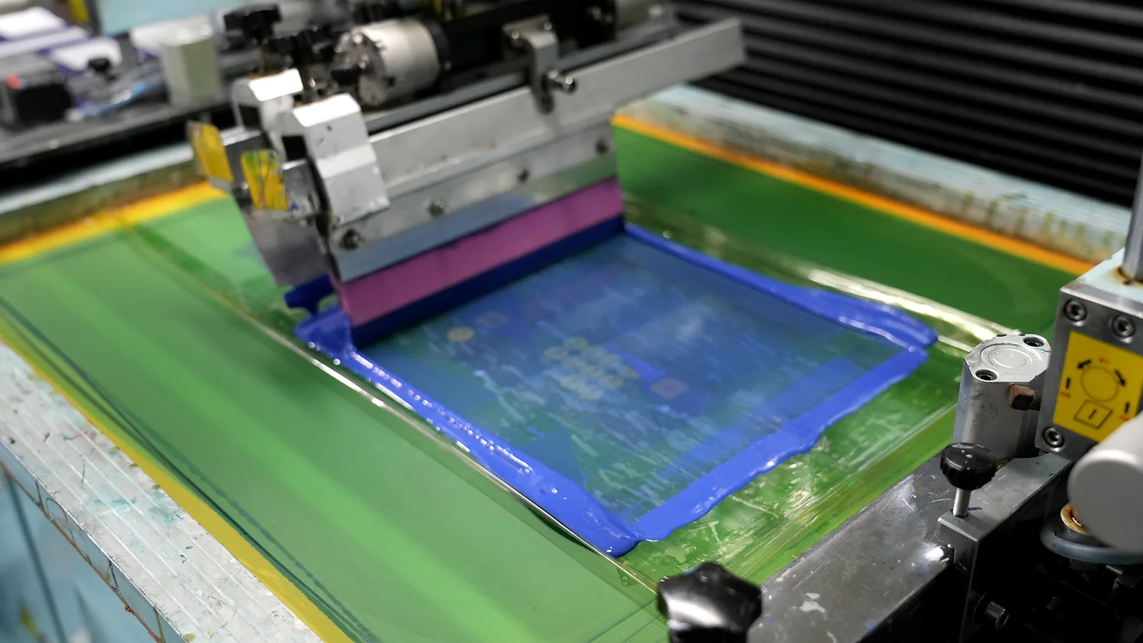
Compare screen, digital, and hybrid overlay printing by color, opacity, gradients, setup, versions, volume, cost, and finished-stack testing.
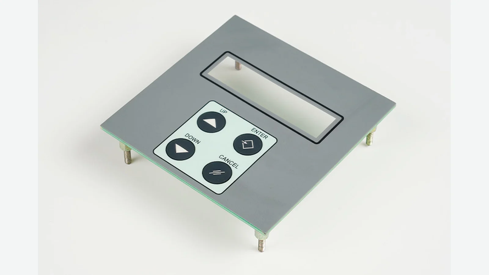
Use this embossed graphic overlay design guide to review 9 checks for geometry, datums, materials, registration, tooling, and production-intent approval.
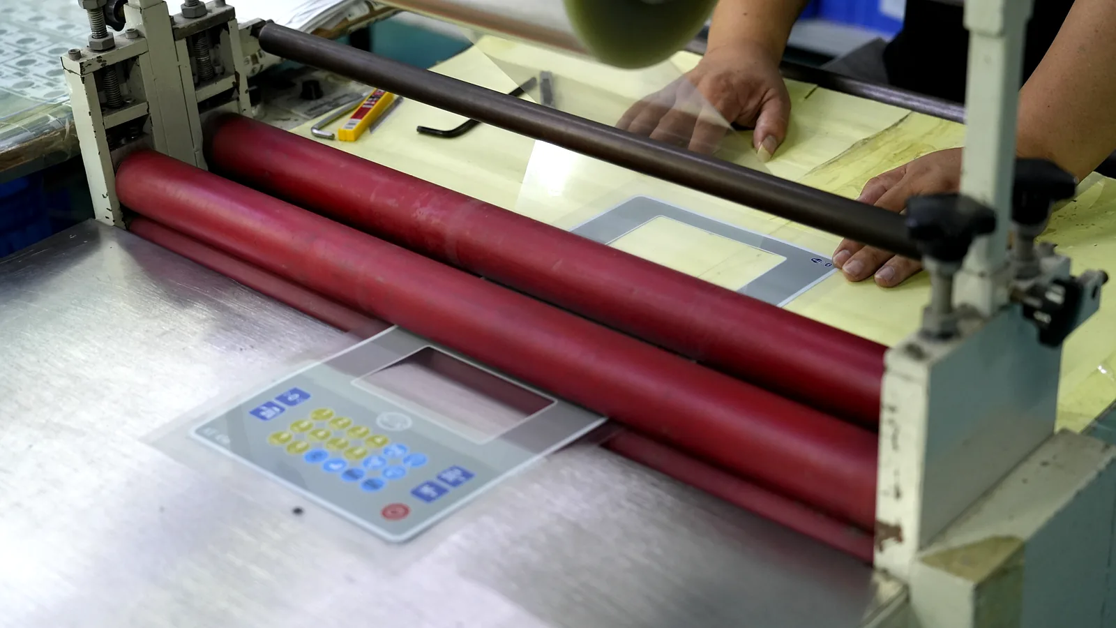
Use this 8-point graphic overlay adhesive selection guide to match surface energy, texture, coating, geometry, temperature, pressure, and validation for OEMs.
Use this graphic overlay prototype checklist to approve 10 checks for artwork, color, windows, embossing, adhesive, fit, and revision control.
Graphic overlay display window design guide for 3 optical states: clear, tinted, and dead-front, with film data, gap rules, drawings, and tests.
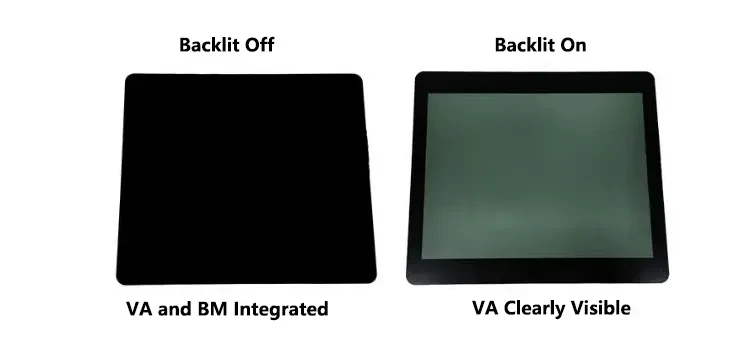
Specify dead front glass panel printing across 6 states, from off-state opacity and lit icons to display, touch, optical registration, and inspection.
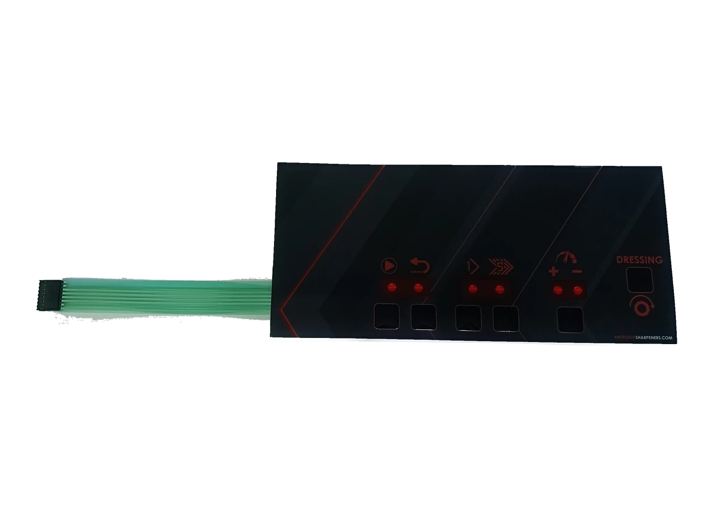
Backlit graphic overlay design guide for diffusion, light-blocking ink, dead-front masking, color shift, registration, and lit/unlit approval.
Plan graphic overlay chemical resistance with a 9-point framework covering cleaner concentration, dwell, wiping, edges, film, ink, and hardcoat.
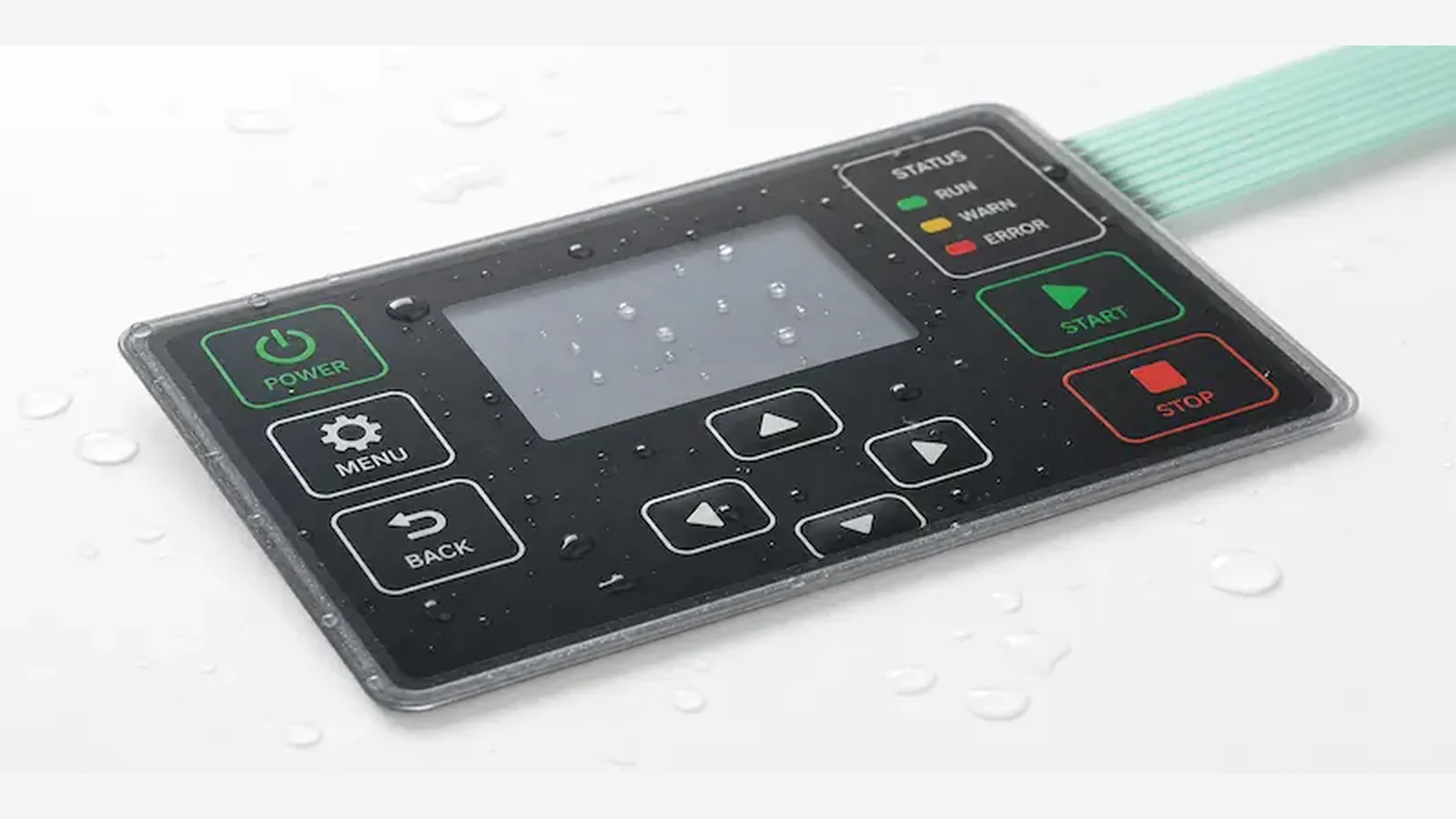
Choose an outdoor graphic overlay material by UV, moisture, temperature, ink, hard coat, adhesive, edges, and 10 validation inputs.
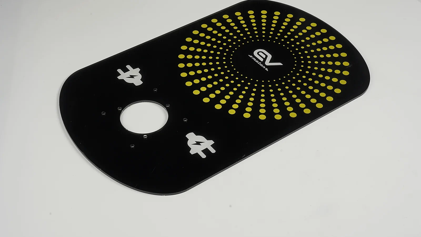
A condition-based engineering comparison of PMMA acrylic and strengthened glass for industrial HMI front panels, covering impact, abrasion, weight, optics, touch integration, mounting, and production validation.
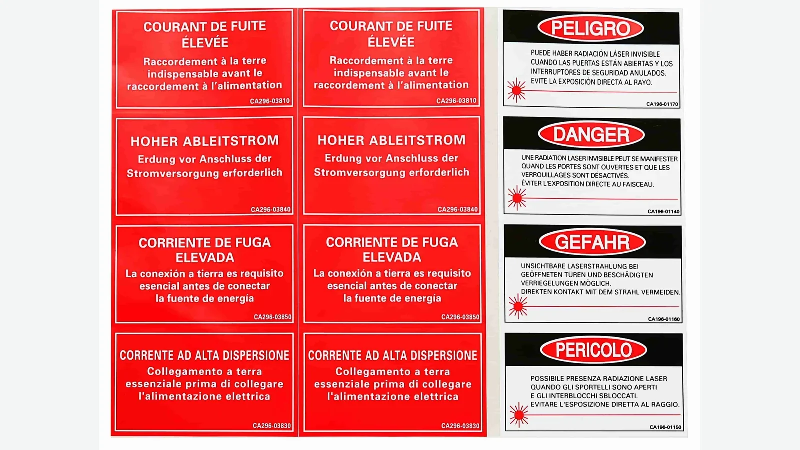
Specify polycarbonate label material for OEM equipment with 10 engineering checks for film grade, finish, print, adhesive, windows, and validation.

Build a metal nameplate specification with 10 controlled decisions for material, marking, mounting, variable data, drawings, and validation for OEM teams.

Compare aluminum vs stainless steel nameplates across 8 engineering factors: corrosion, weight, heat, abrasion, marking, mounting, and lifecycle cost.
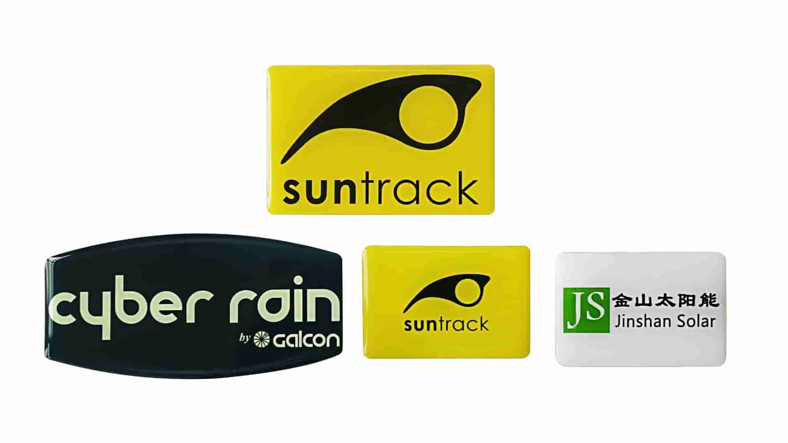
Compare epoxy vs polyurethane domed labels across 8 engineering factors: UV yellowing, flexibility, chemicals, dome profile, substrates, and testing.
Compare 3 metal nameplate marking methods—etched, anodized, and printed—by permanence, color, resolution, alloys, outdoor use, testing, and cost drivers.
Use graphic overlay failure analysis to trace 4 symptoms—peeling, faded legends, cracks, and window haze—to evidence, tests, and corrective-action steps.
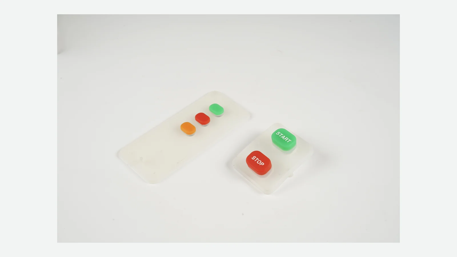
Compare membrane keypad vs silicone keypad across 10 engineering decisions: feel, stack, sealing, tooling, graphics, lighting, assembly, and validation.
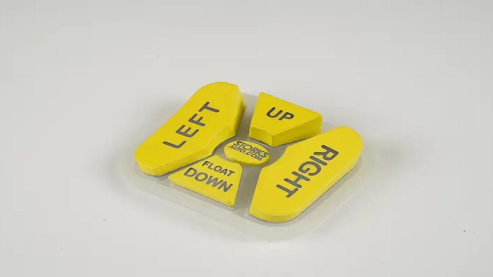
Use this silicone rubber keypad design guide to define 10 OEM inputs for force, travel, contacts, tooling, lighting, sealing, drawings, and validation.
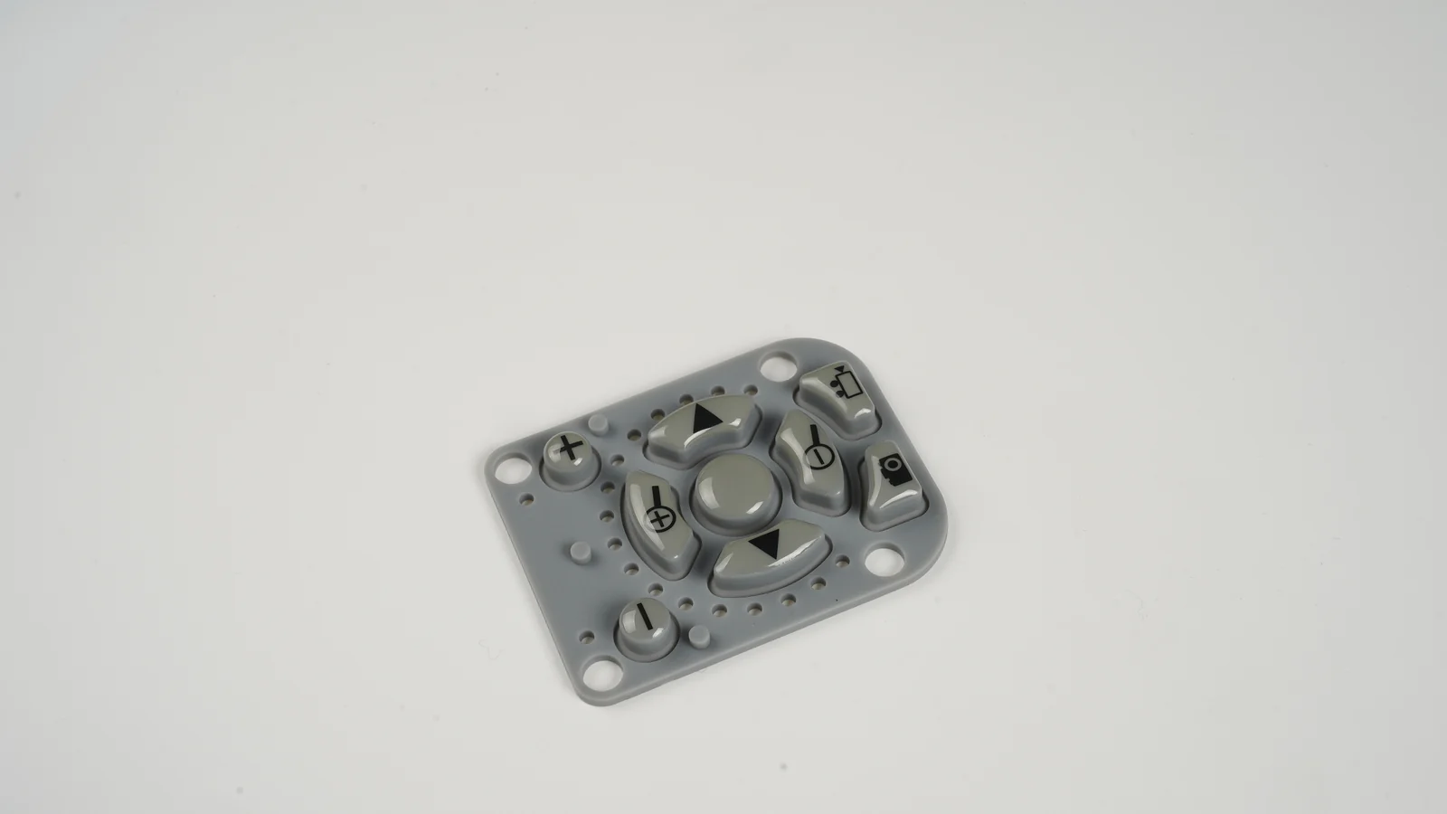
Set silicone keypad carbon pill resistance by circuit budget, then control load, PCB geometry, test method, contamination, and 7 approval stages.
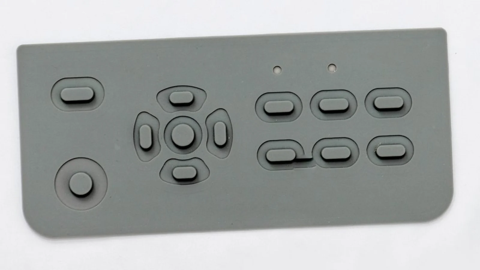
Approve a silicone rubber keypad prototype with 10 checks for tooling, shrinkage, force, legends, backlighting, assembly fit, and production release.
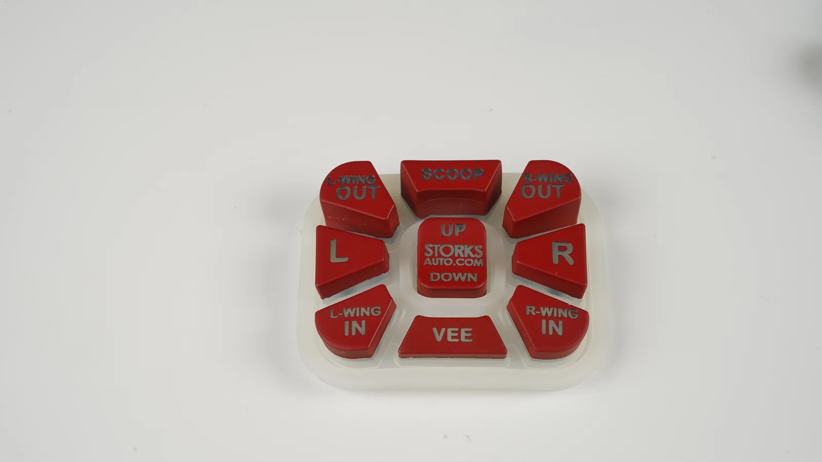
Specify a laser etched silicone keypad with a 9-point guide to coating stacks, backlight contrast, abrasion, chemical exposure, and sample approval steps.
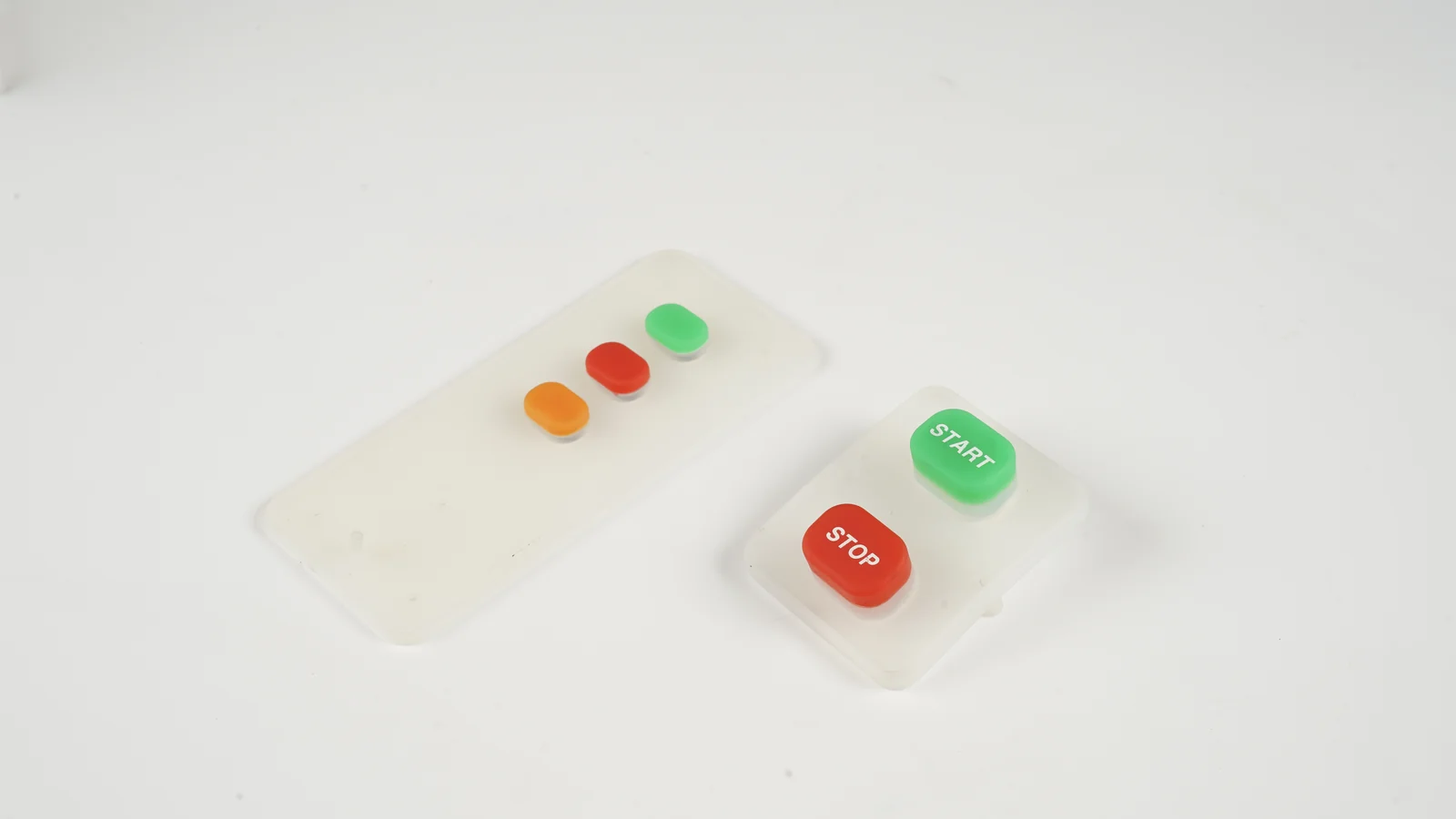
Specify silicone keypad actuation force with 10 curve events, web geometry, travel, return force, test controls, and a sample-approval checklist.
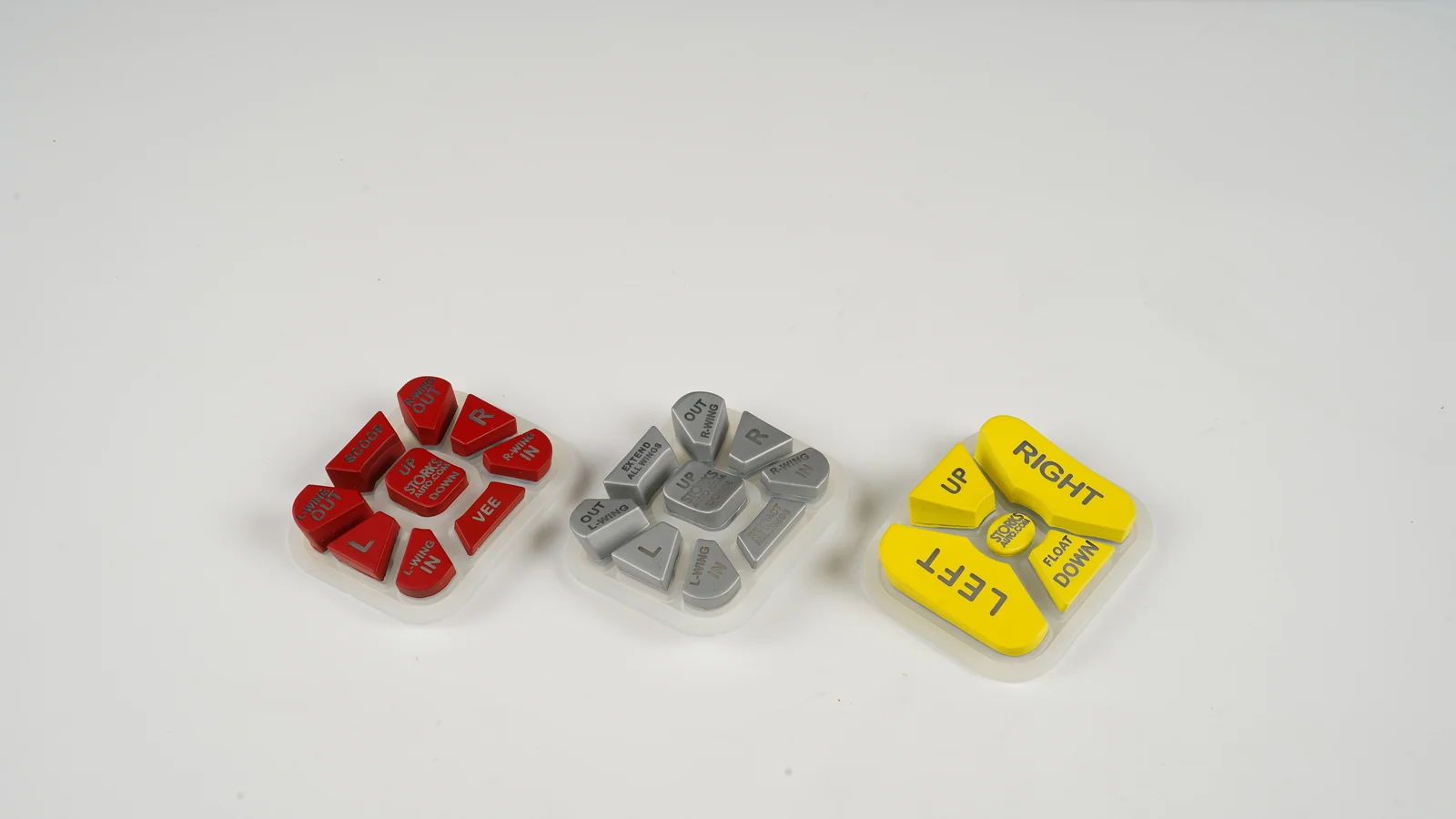
Use this 10-point silicone keypad hardness selection guide to connect Shore A, compression set, return force, temperature, geometry, sealing, and ageing.
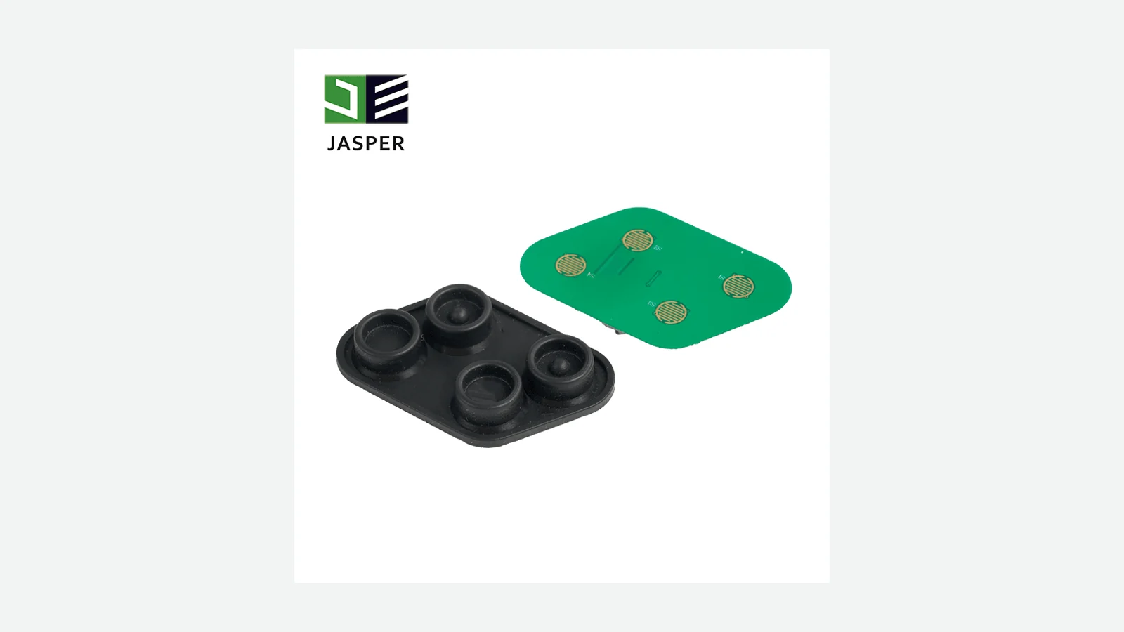
Compare conductive rubber keypad contacts across 8 engineering factors: resistance, geometry, wear, PCB design, process control, and sample testing.
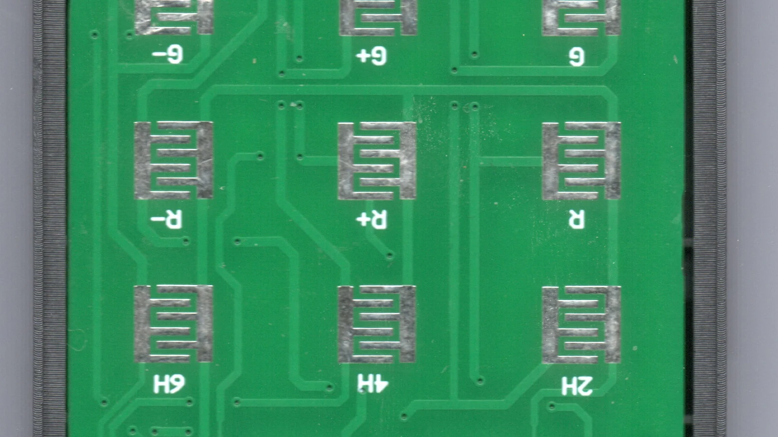
Coordinate 6 variables in rubber keypad PCB contact design: pad geometry, pill overlap, finish, compression, contamination, and electrical validation.
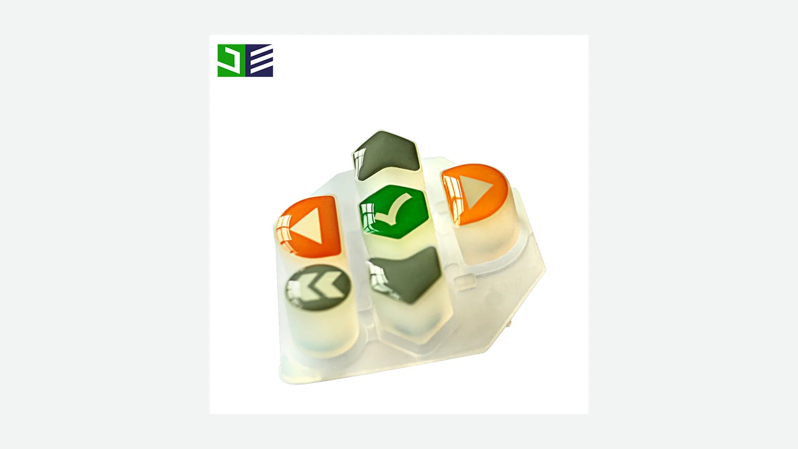
Use this backlit silicone keypad design guide to compare 4 optical architectures, place LEDs, control hot spots, and approve laser-etched legends.
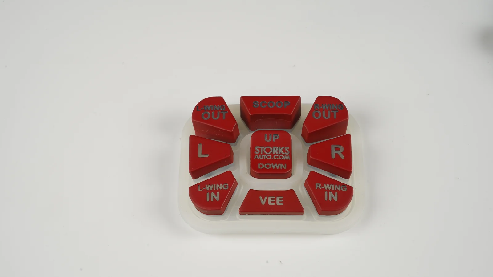
Compare 5 legend constructions and test silicone keypad legend durability against abrasion, cleaning chemicals, key flex, heat, and UV.
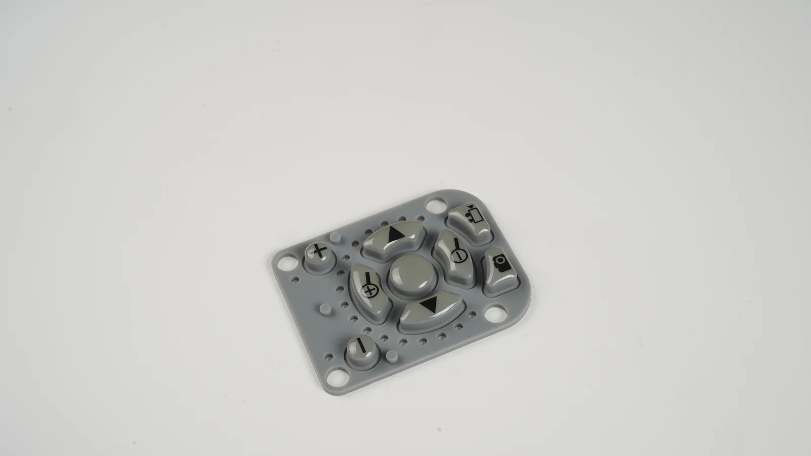
Silicone keypad assembly design guide covering 9 decisions for compression, retention, bezel support, PCB gap, tolerances, service, and testing.
Silicone keypad sealing design guide: map 8 enclosure boundaries, control gasket compression, and validate the complete assembly—not a loose keypad.
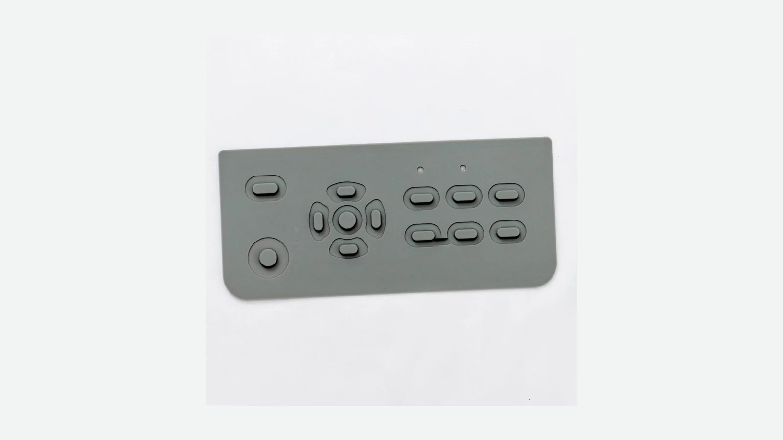
Use this 10-gate silicone keypad sample approval checklist to verify force curves, return, contacts, legends, lighting, assembly fit, and revision evidence.
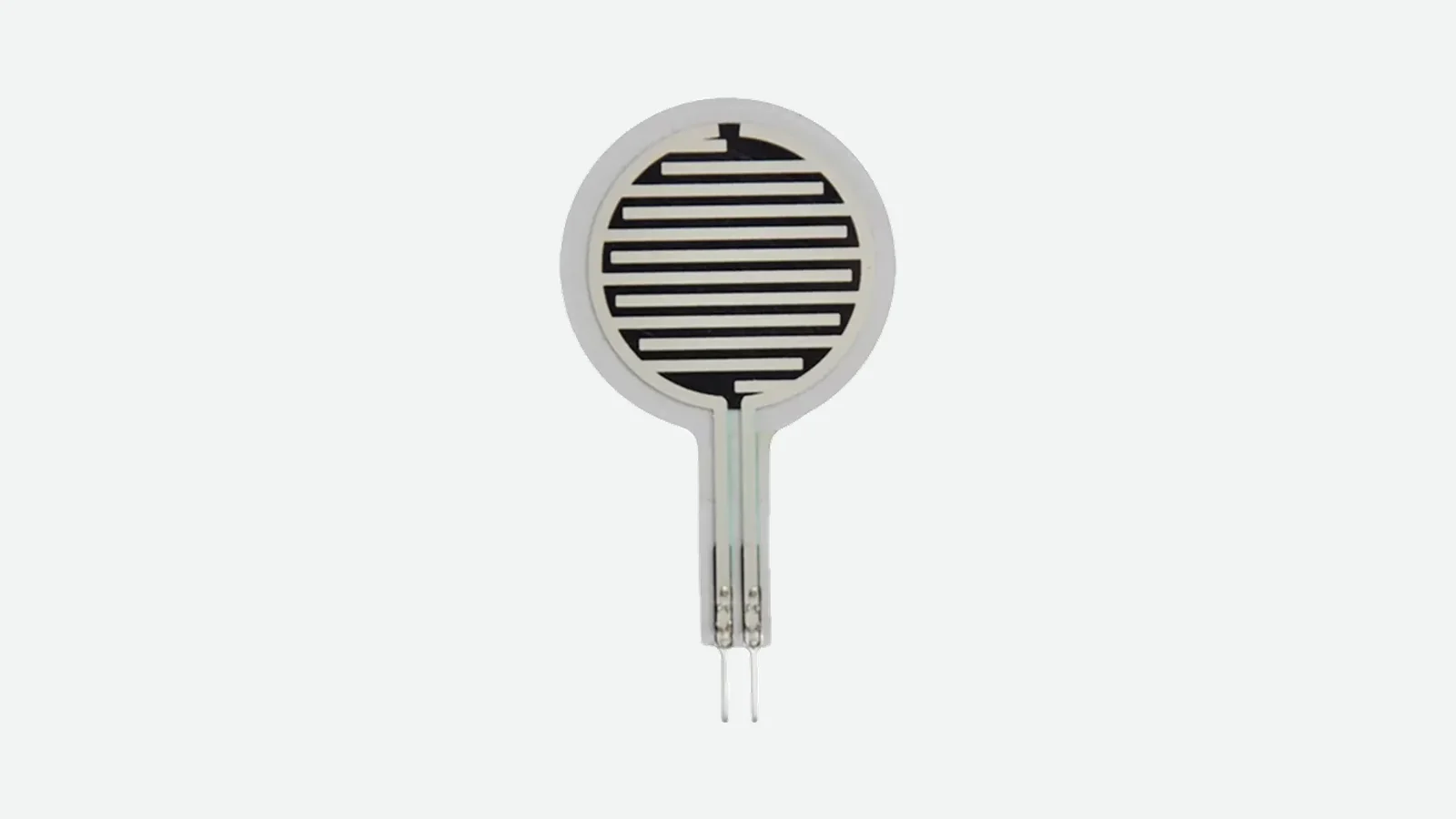
An OEM engineering guide to force sensing resistor construction, nonlinear response, repeatability, drift, calibration, and FSR-versus-load-cell decisions.
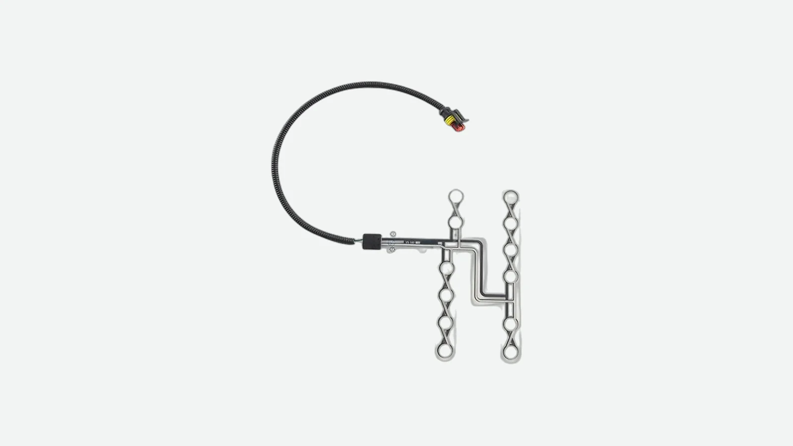
Pressure sensor mat calibration guide for setting T_on, T_off, hysteresis, guard bands, and validation tests from installed-seat data.
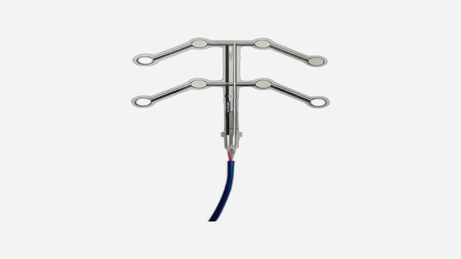
How does a seat occupancy sensor work? Compare 6 architectures, detection logic, seat-stack effects, ISO standards, and validation inputs for OEM programs.
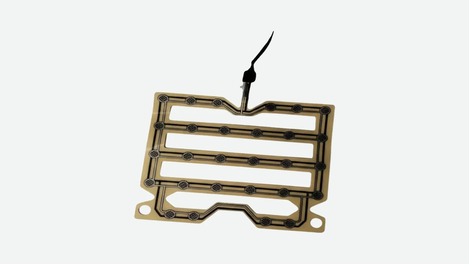
Seat pressure sensor vs occupancy sensor: compare 6 architectures, output limits, validation tests, and the right choice for an automotive seat system.
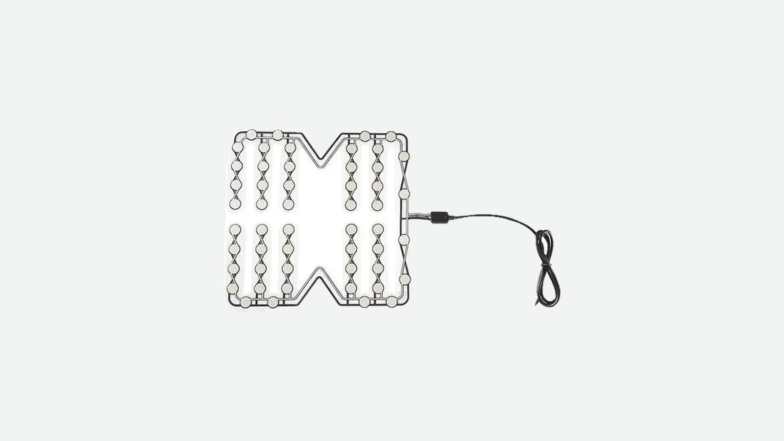
Pressure sensor mat design guide covering 9 OEM decisions: sensing zones, load paths, flexible tails, lamination, mounting, and validation.

Use a 4-level seat occupancy sensor testing matrix for load, release, environment, life, connector, diagnostics, and EOL acceptance—without universal limits.
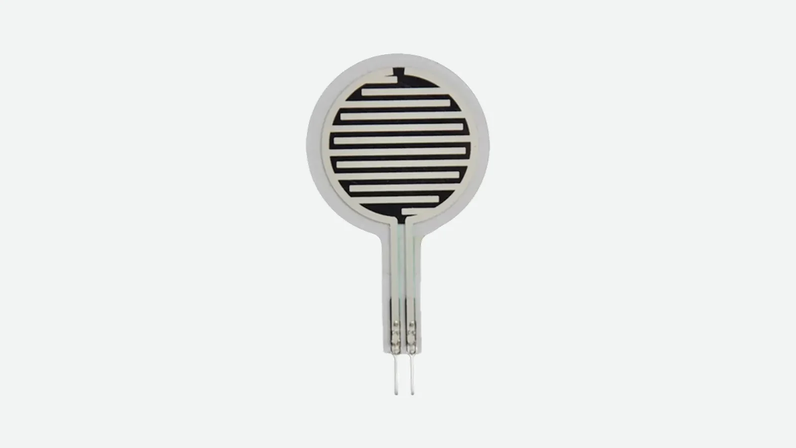
Force sensing resistor vs strain gauge: compare 9 engineering criteria for thin seat detection, from load path and drift to calibration and electronics.
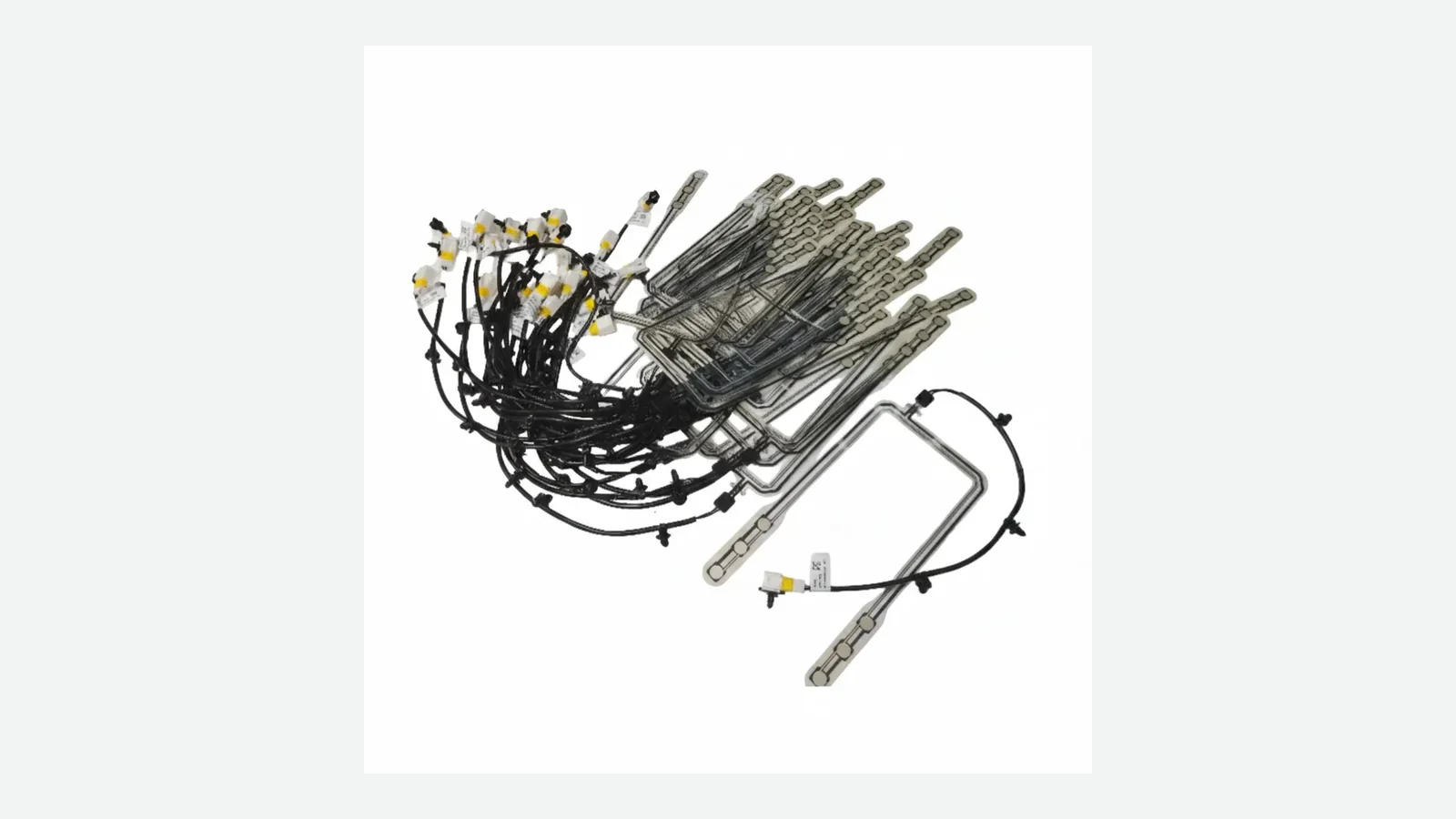
Use this 10-point flexible pressure sensor array design guide to define seat zones, routing, crosstalk, tail geometry, calibration, and validation steps.
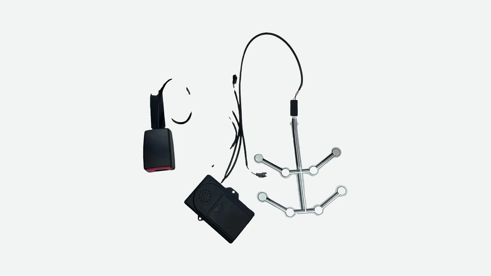
Seat belt reminder sensor integration guide for OEMs: align 2 independent inputs, thresholds, debounce, harness diagnostics, and 4 validation layers.
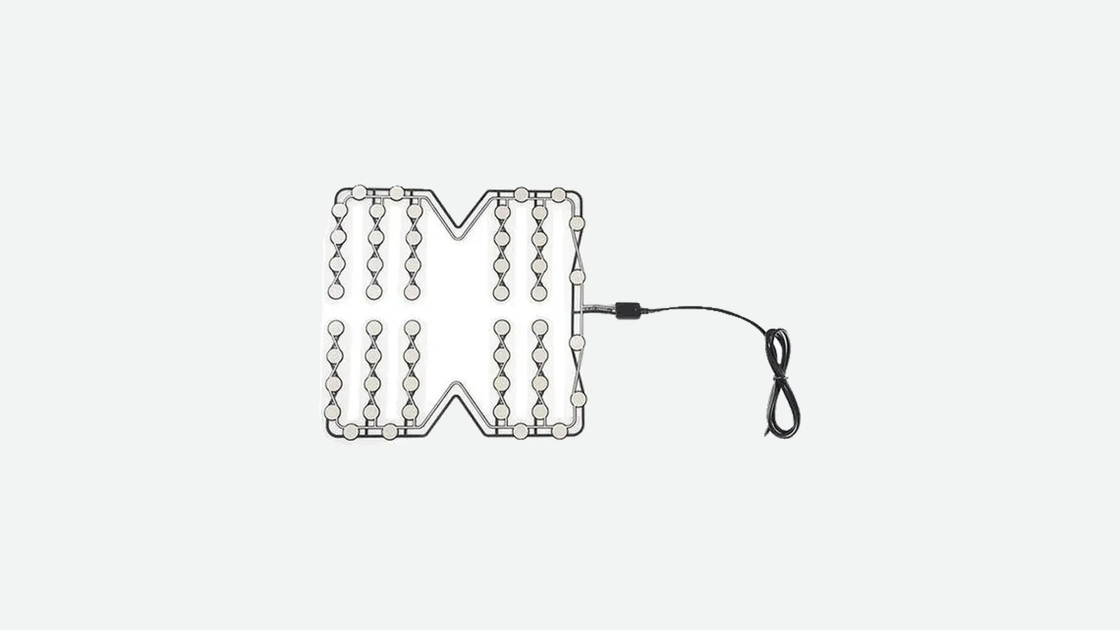
Use a 10-point bus seat occupancy sensor design guide to control load paths, harnesses, cleaning, false states, validation, and fleet boundaries for release.
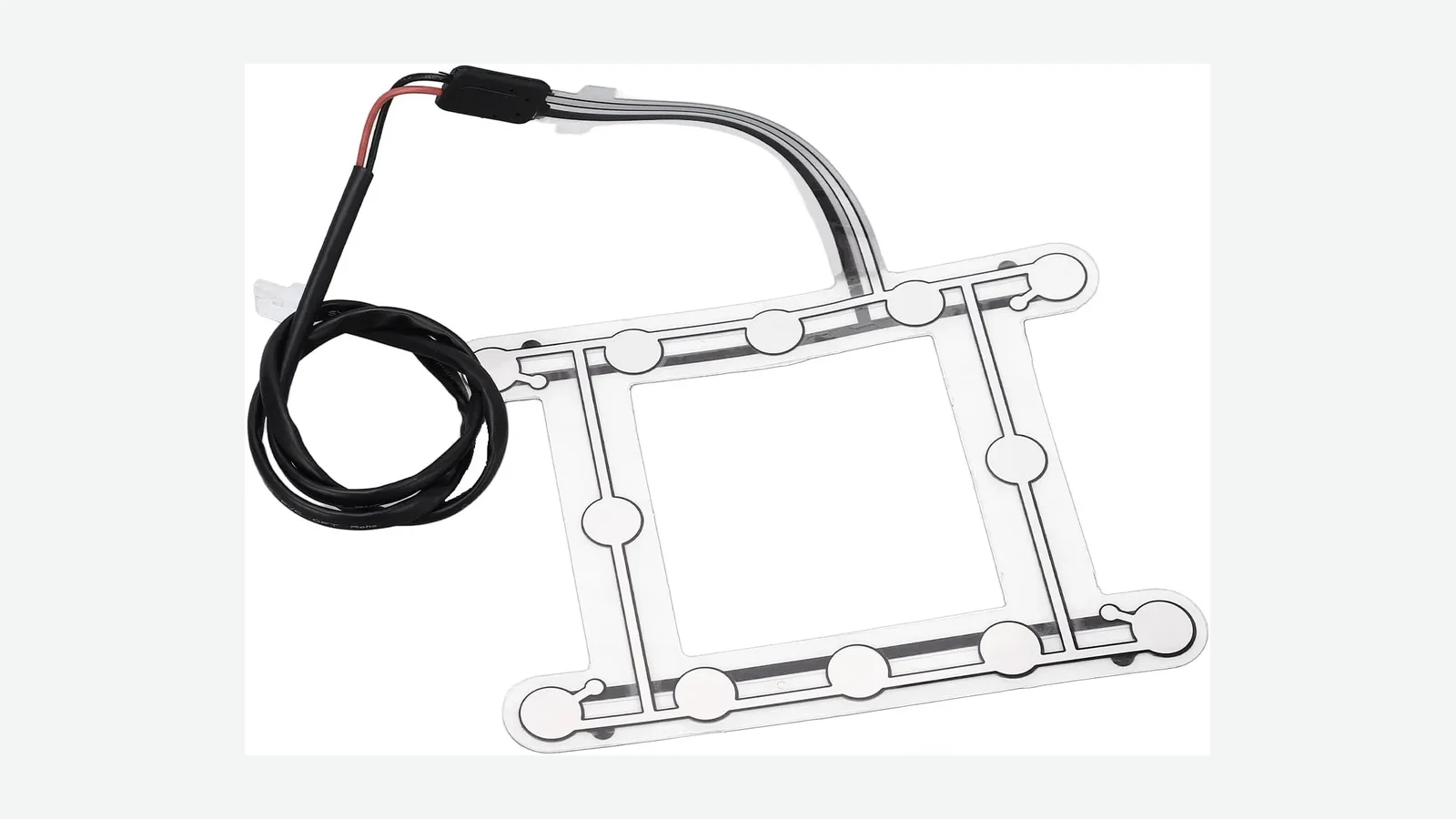
Plan seat pressure sensor placement with a 10-point review of foam, trim, posture, support, installation, and finished-seat validation for OEM seat programs.
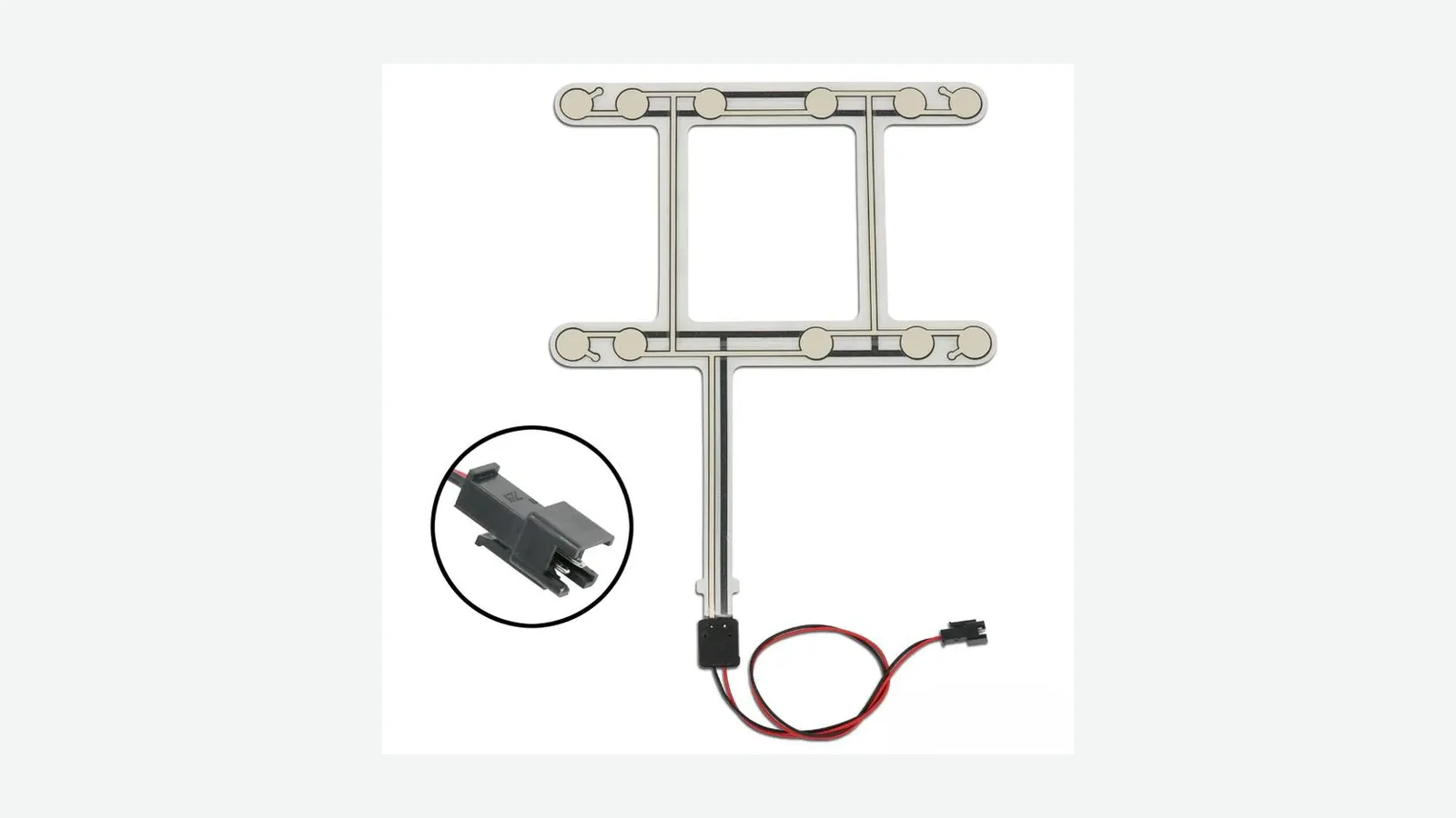
Trace passenger seat occupancy sensor false positives through 5 layers, then define thresholds, exclusions, and a validation matrix for the real seat.
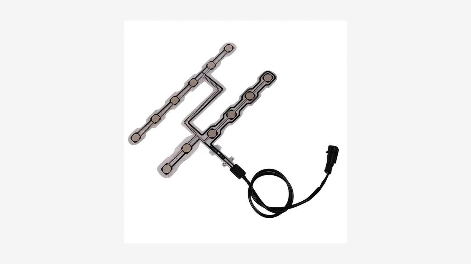
Seat sensor connector design guide for pressure-mat tail exits, keying, strain relief, seat motion, harness routing, assembly, and validation.
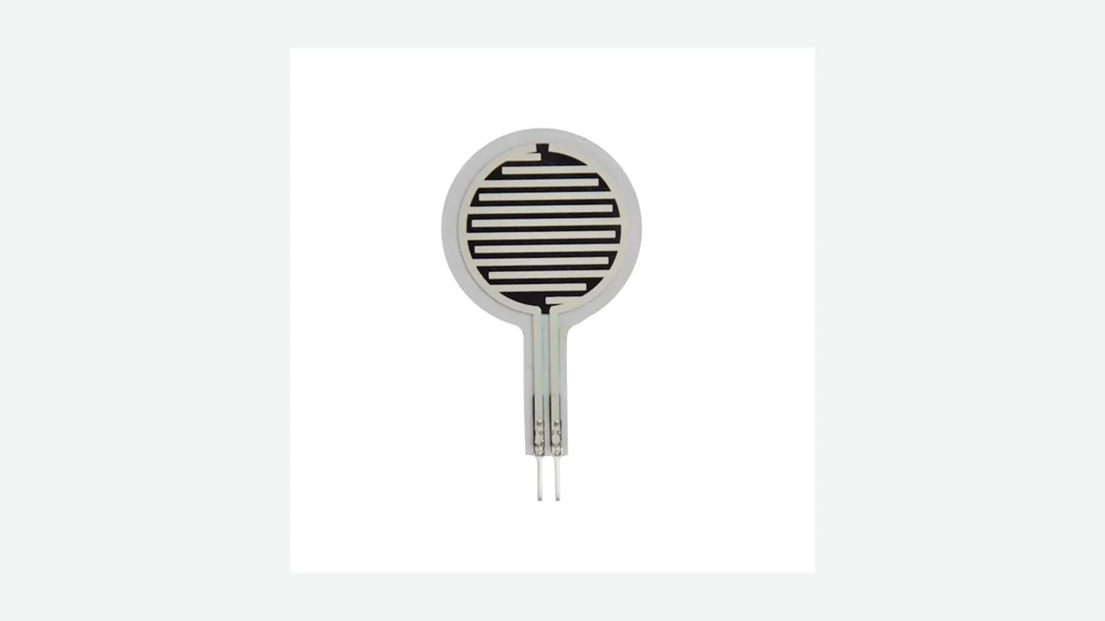
Diagnose seat pressure sensor drift across 6 layers, then define temperature, dwell, recovery, and stability limits before seat validation.
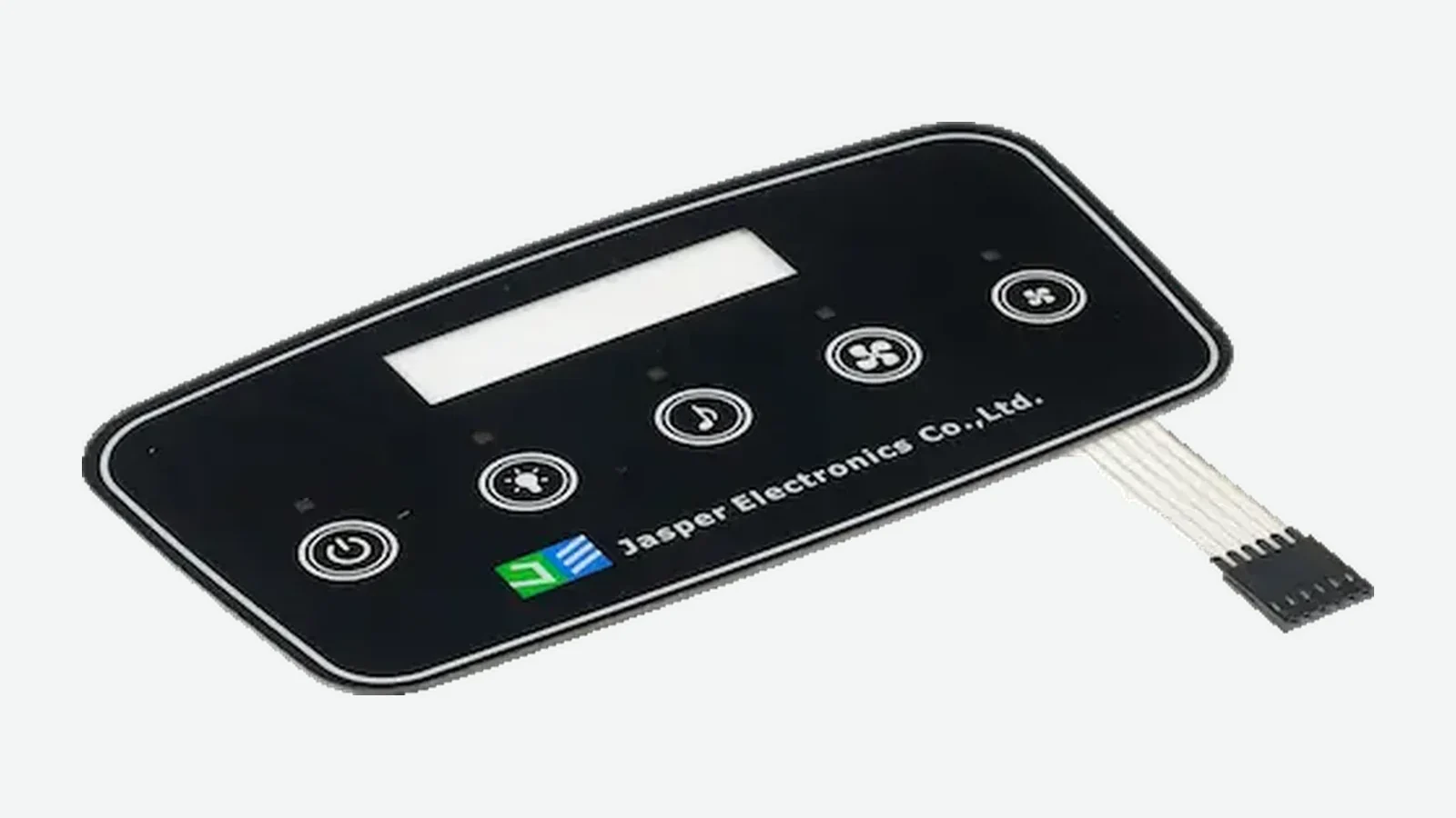
Capacitive touch vs membrane switch: compare 8 engineering factors covering feedback, gloves, moisture, EMI, power, controllers, and validation.
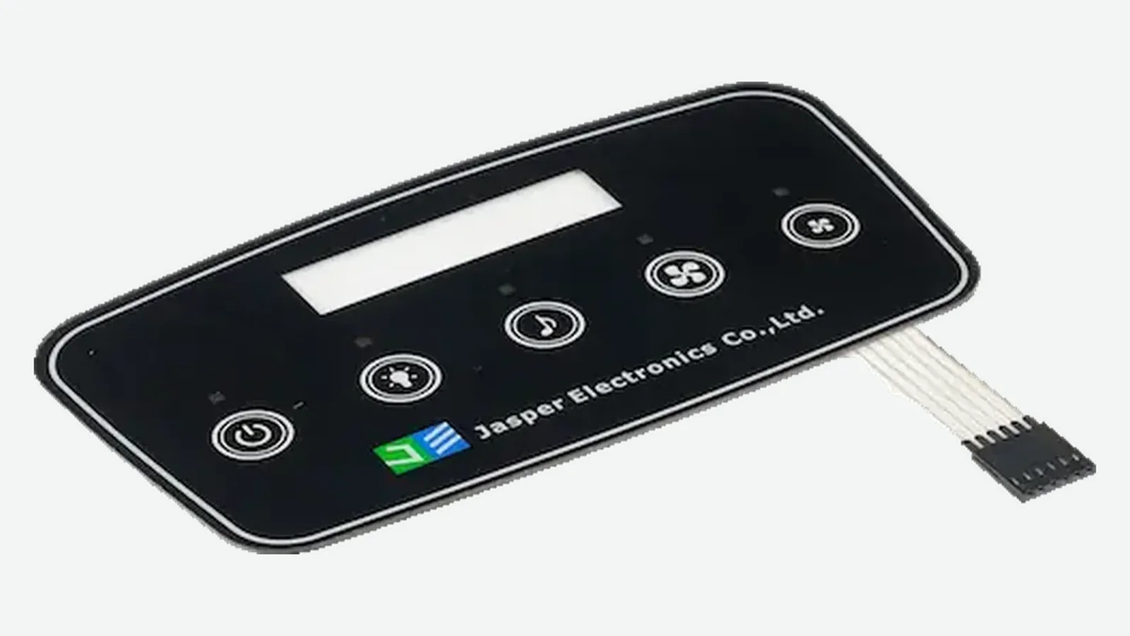
Compare capacitive vs resistive touch panels across 8 OEM criteria: gloves, water, optics, durability, controllers, multi-touch, service, and cost.

An engineering guide to defining glove inputs, wet-finger sensing, water rejection, cover stacks, electrodes, grounding, controller states, and PCAP validation.

Custom capacitive touch panel design guide for PCAP drawings, cover lenses, sensors, FPCs, controllers, bonding, water, gloves, and validation.
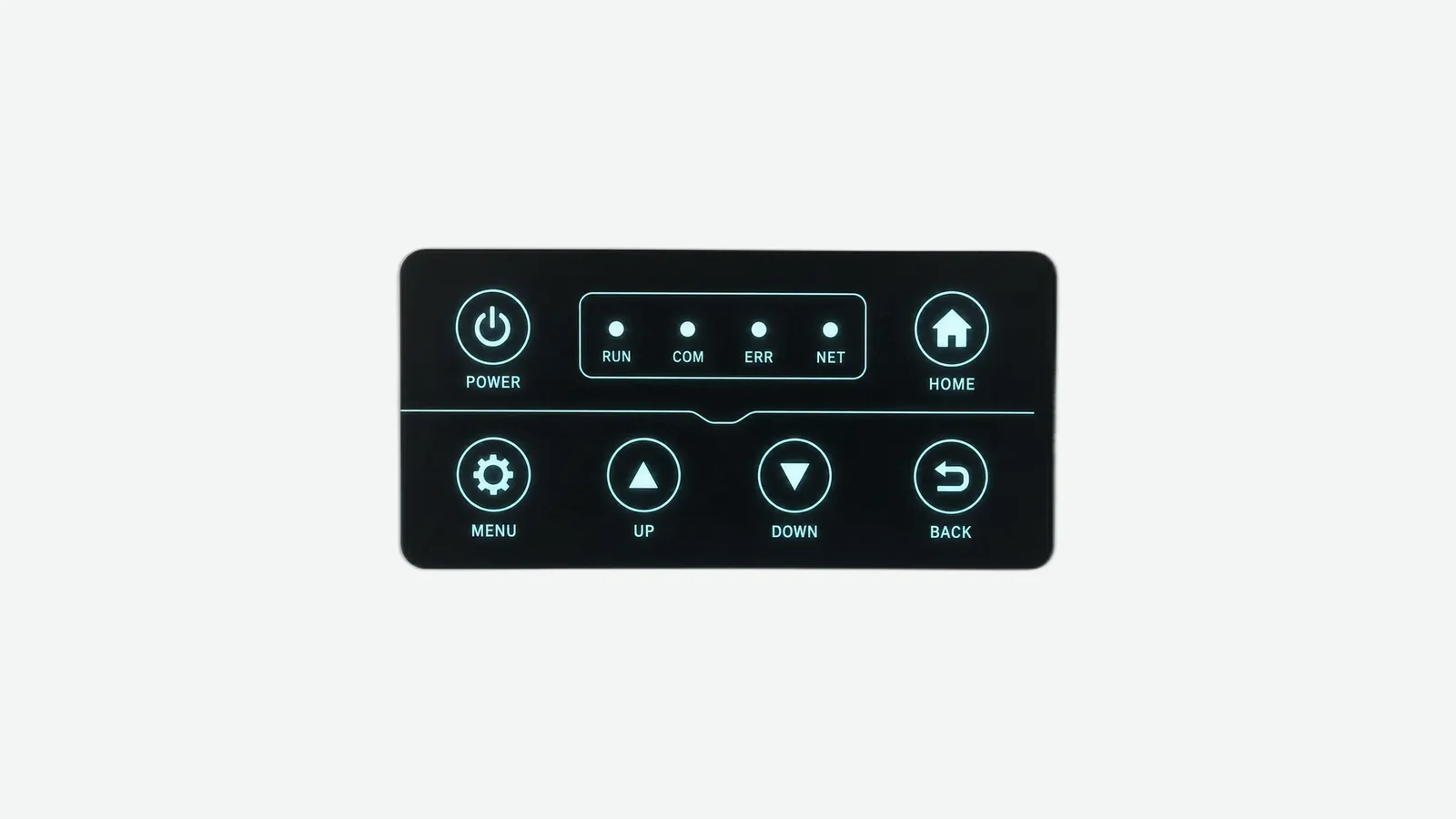
Touch panel EMI ESD design guide to grounding, shields, display and charger noise, flex routing, protection, and four IEC immunity methods.
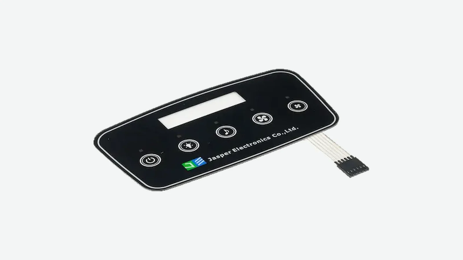
Projected capacitive touch panel technology explained through 7 stack layers, mutual and self sensing, coordinate output, integration limits, and testing.
Capacitive multi touch panel design guide with 10 freeze criteria for electrode pitch, PCAP edges, routing, cover stack, controller, and validation.

Choose capacitive touch cover lens thickness by material, bond stack, air gaps, electrode pitch, gloves, controller tuning, noise, and validation.
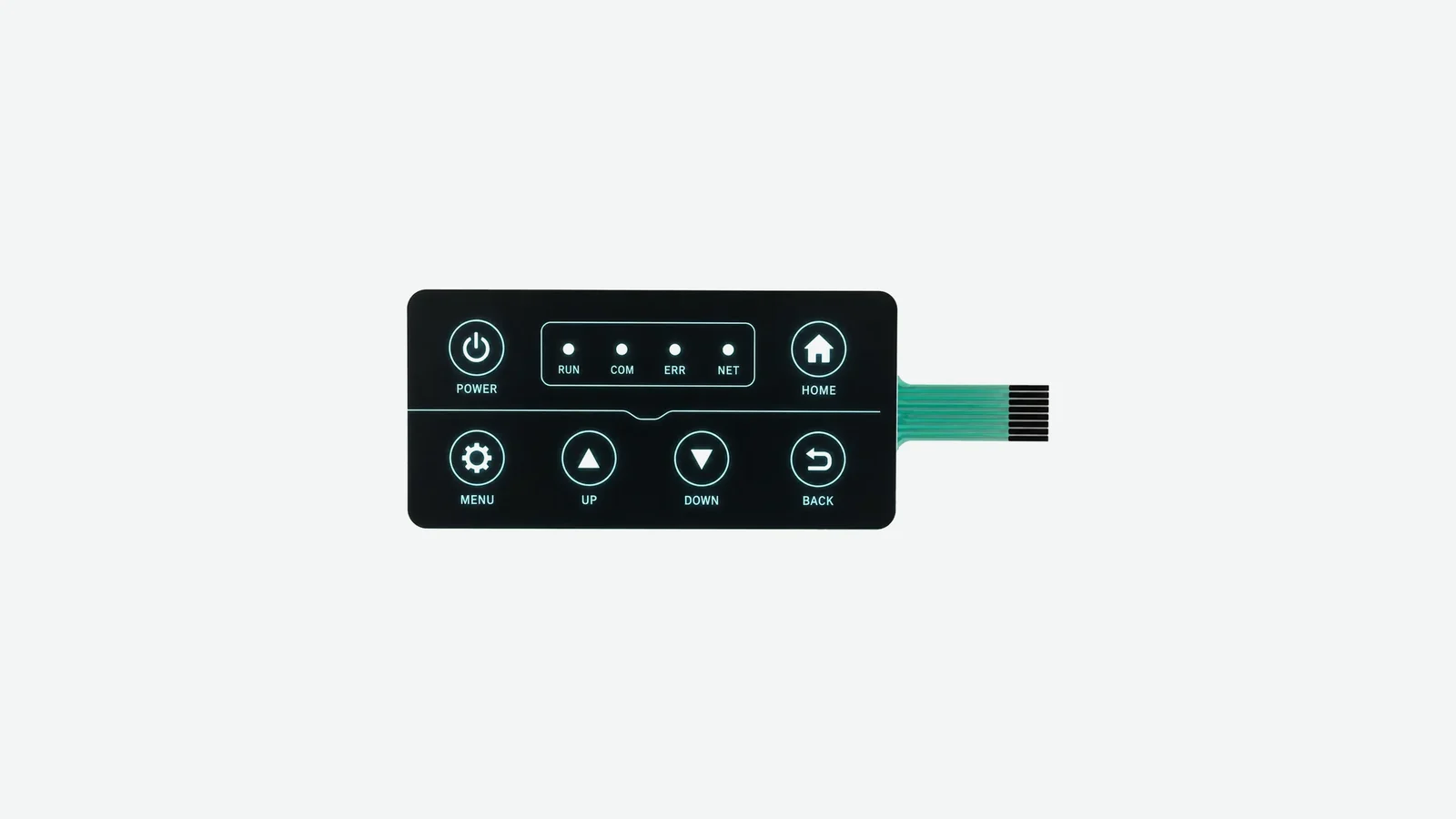
Choose a capacitive touch display window stack using 9 checks for reflection, parallax, serviceability, adhesive control, registration, and testing.
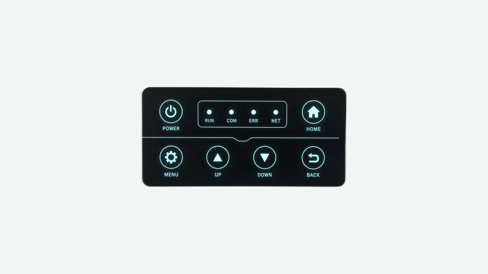
Design a backlit capacitive touch panel by coordinating dead-front ink, LED layout, diffusion, electrodes, controller tuning, and sample tests.

Capacitive touch keypad vs switch: compare channels, key spacing, controller topology, feedback, layouts, and validation before choosing an HMI.
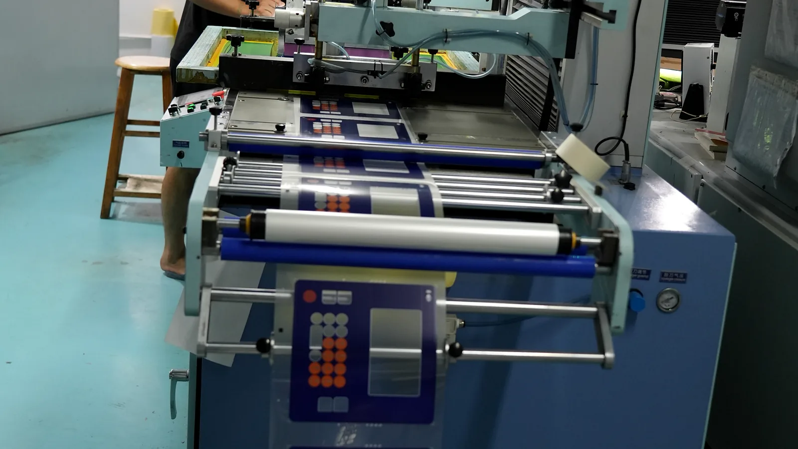
Use this capacitive touch controller tuning plan to capture channel data, isolate false triggers, and validate noise across a 7-step test sequence.
Capacitive touch panel prototype validation across 12 checks for geometry, optics, edges, gloves, water, noise, bonding, and approval records.
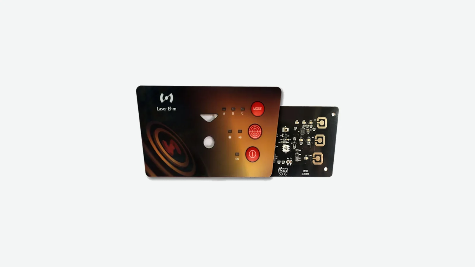
Use this 10-point capacitive HMI front panel design guide to align the cover lens, sensor, adhesive, display, bezel, controller, grounding, and enclosure.
What is an HMI panel? See its hardware layers, 5 architecture options, integration boundaries, drawing inputs, and validation responsibilities.
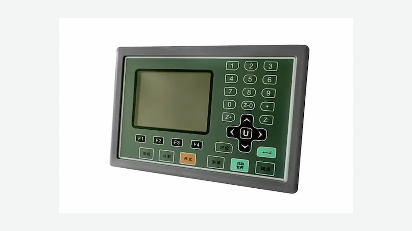
Compare HMI panel vs membrane switch panel designs by display need, tactile feedback, software, sealing, cost, service, life, and validation.
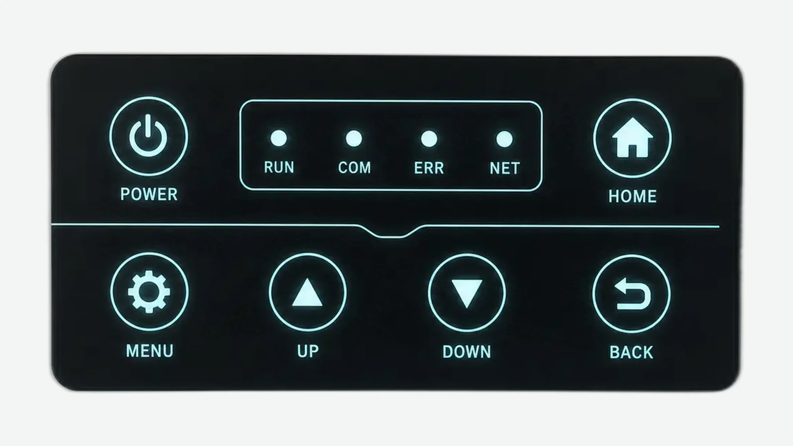
Compare HMI optical bonding, cover lens air gaps, perimeter adhesive, OCA and LOCA for optics, stress, serviceability and validation.
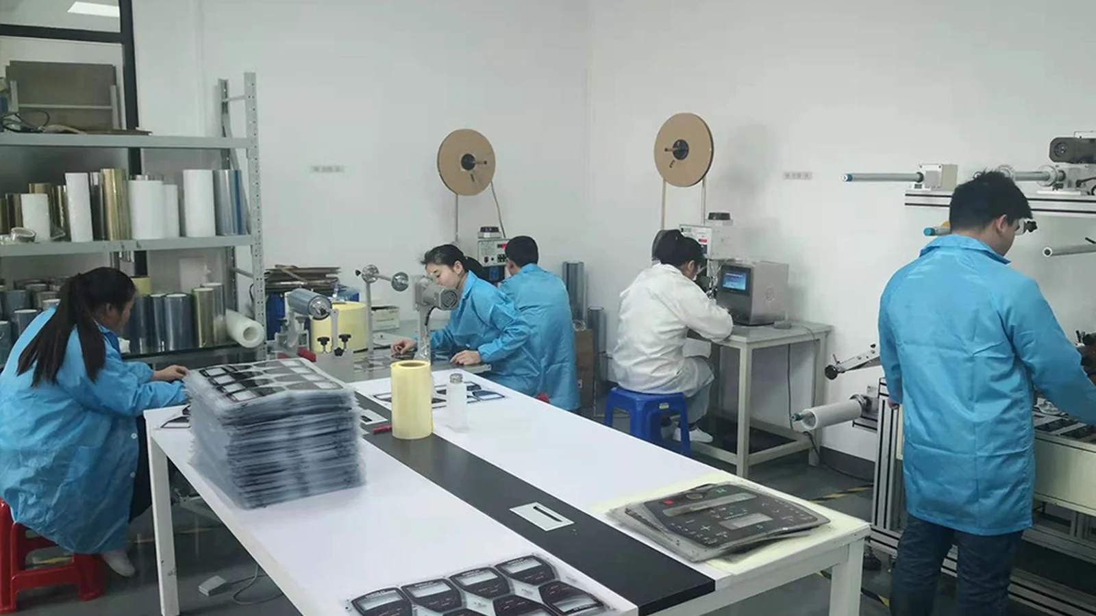
Use this HMI panel assembly design checklist to close 10 release gates for stack-up, drawings, tolerances, sealing, connectors, and validation.
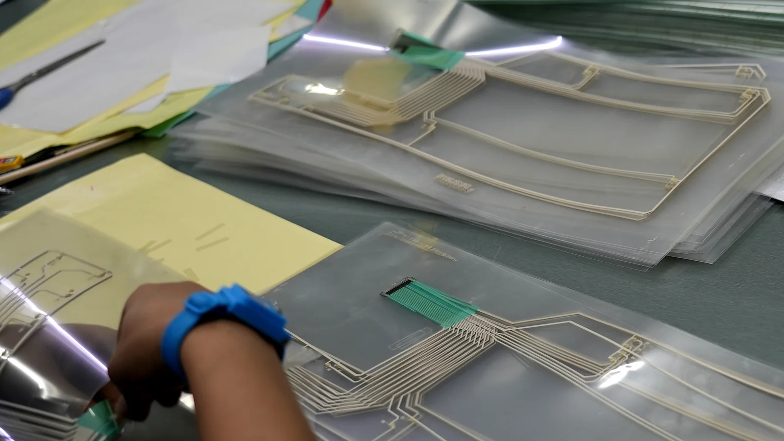
Select an industrial adhesive for HMI assemblies with a 10-point framework for substrates, bond width, environment, process, rework, testing, and validation.
Plan an HMI panel tolerance stack across 4 functional loops using datum mapping, worst-case math, process capability, and validation for OEM assemblies.
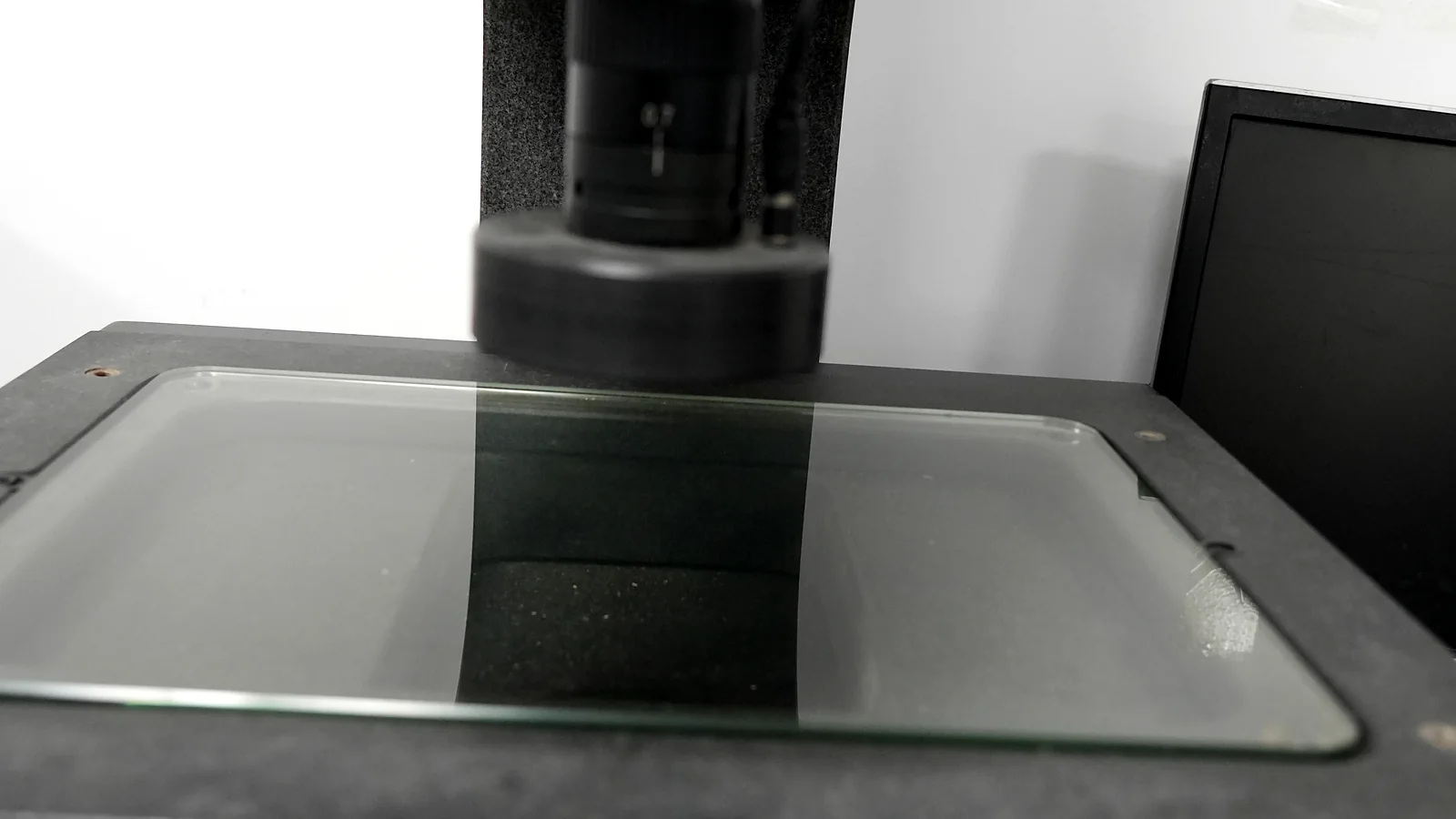
HMI display window alignment guide with 10 checks for tolerance stacks, parallax, datum control, viewing zones, drawings, and sample approval.
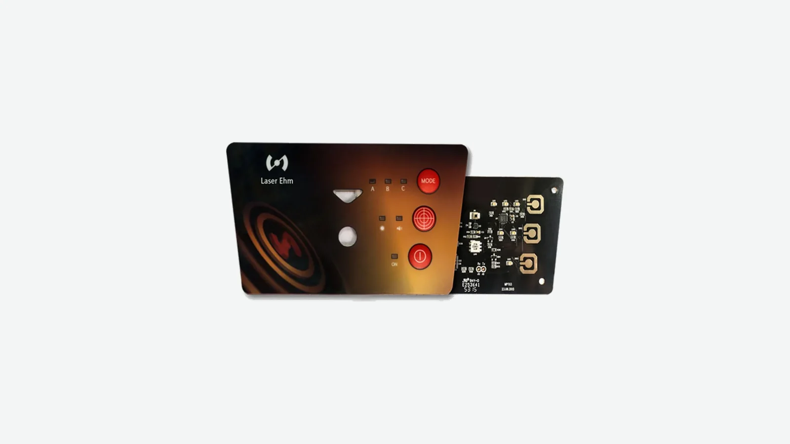
Plan a membrane switch HMI assembly across 6 interfaces: overlay, circuit, display, connector, support and sealing, with clear test and approval boundaries.
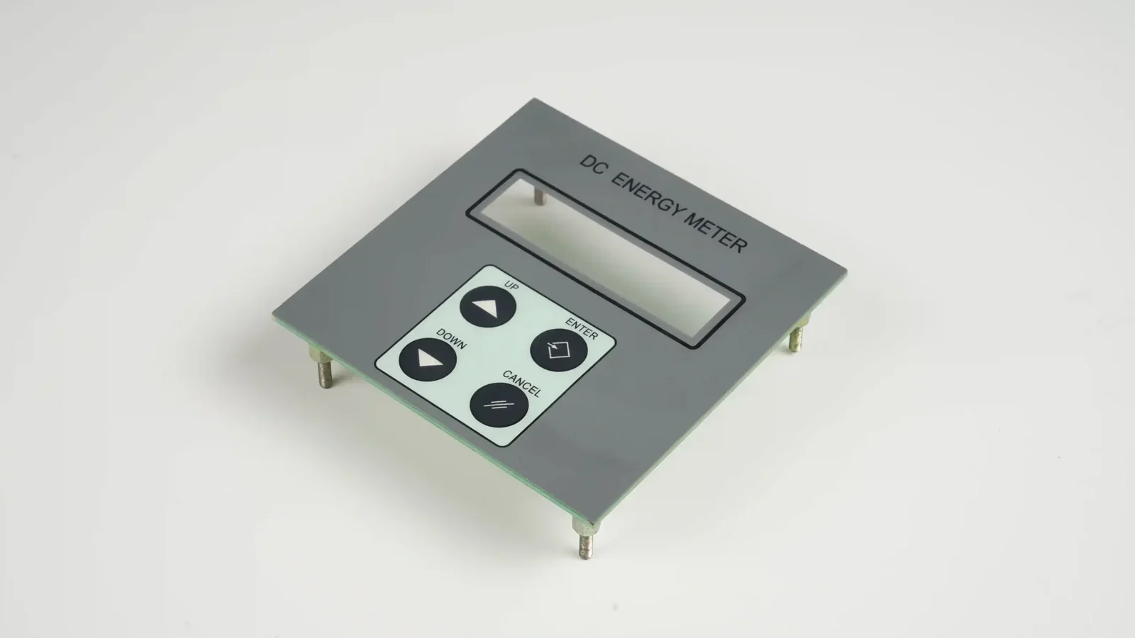
Compare PCB FPC HMI assembly options for support, routing, components, connectors, thickness, strain relief, access, testing, and design release.
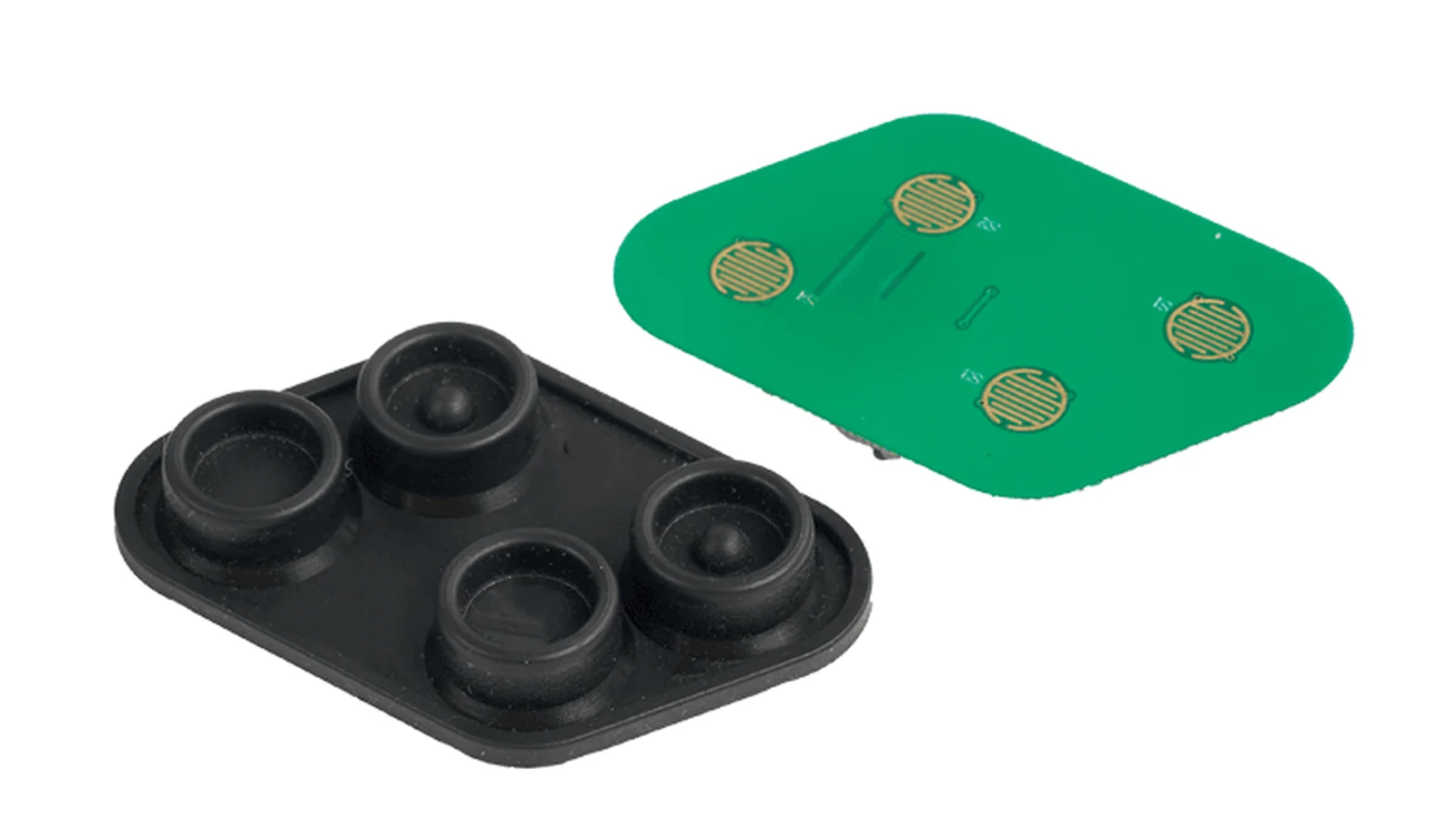
Use this 10-point silicone keypad HMI assembly design guide to set compression, PCB contact alignment, bezel support, tolerances, and approval tests.

An OEM guide to defining a capacitive HMI validation matrix for bonding, optics, touch response, gloves, water, EMC, climate, mechanical fit, cosmetics, and evidence.

Calculate industrial HMI panel total cost of ownership with 10 supplier-review criteria for tooling, yield, validation, service, and obsolescence.
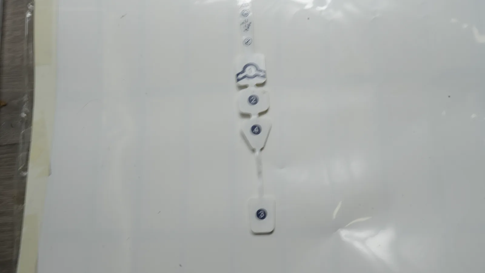
See how screen printed medical electrodes are made in 8 controlled stages, from flexible substrate and conductive ink to converting and validation.
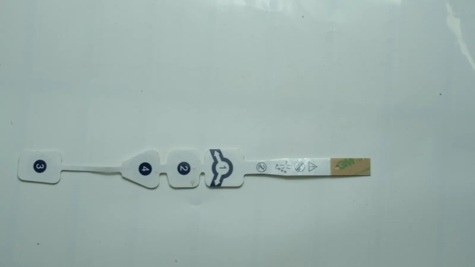
Custom medical electrode design guide with 10 inputs for geometry, printed circuits, materials, hydrogel, connectors, packaging, and validation.

Map the medical electrode layer stack across 5 interfaces: substrate, conductive ink, dielectric, adhesive, and skin—plus testing boundaries.

Compare Ag/AgCl vs carbon electrodes by role, polarization, process, substrate, cost drivers, and validation for medical and biosensor circuits.
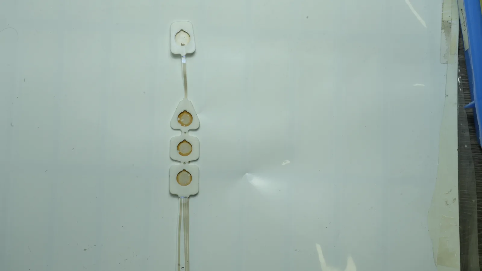
An engineering comparison of hydrogel and dry medical-electrode interfaces across motion, wear, packaging, electronics, and finished-device validation.
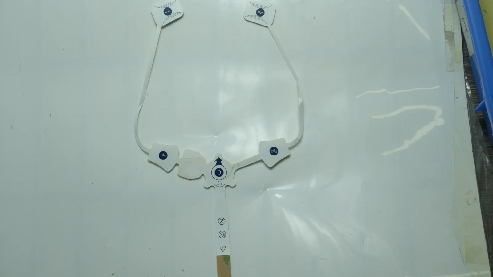
Recording vs stimulation electrodes differ in signal direction, area, materials, connectors, electronics, tests, and finished-device validation.
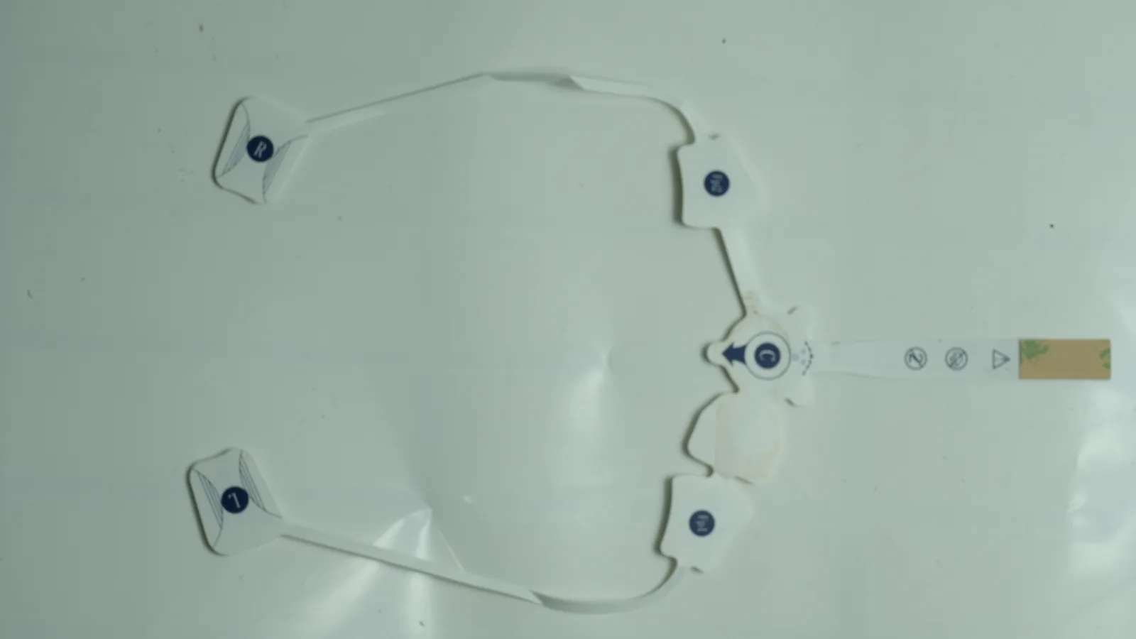
Compare ECG vs EEG vs EMG electrodes across 8 engineering factors: signal context, placement, geometry, wear, connections, failure, and validation.
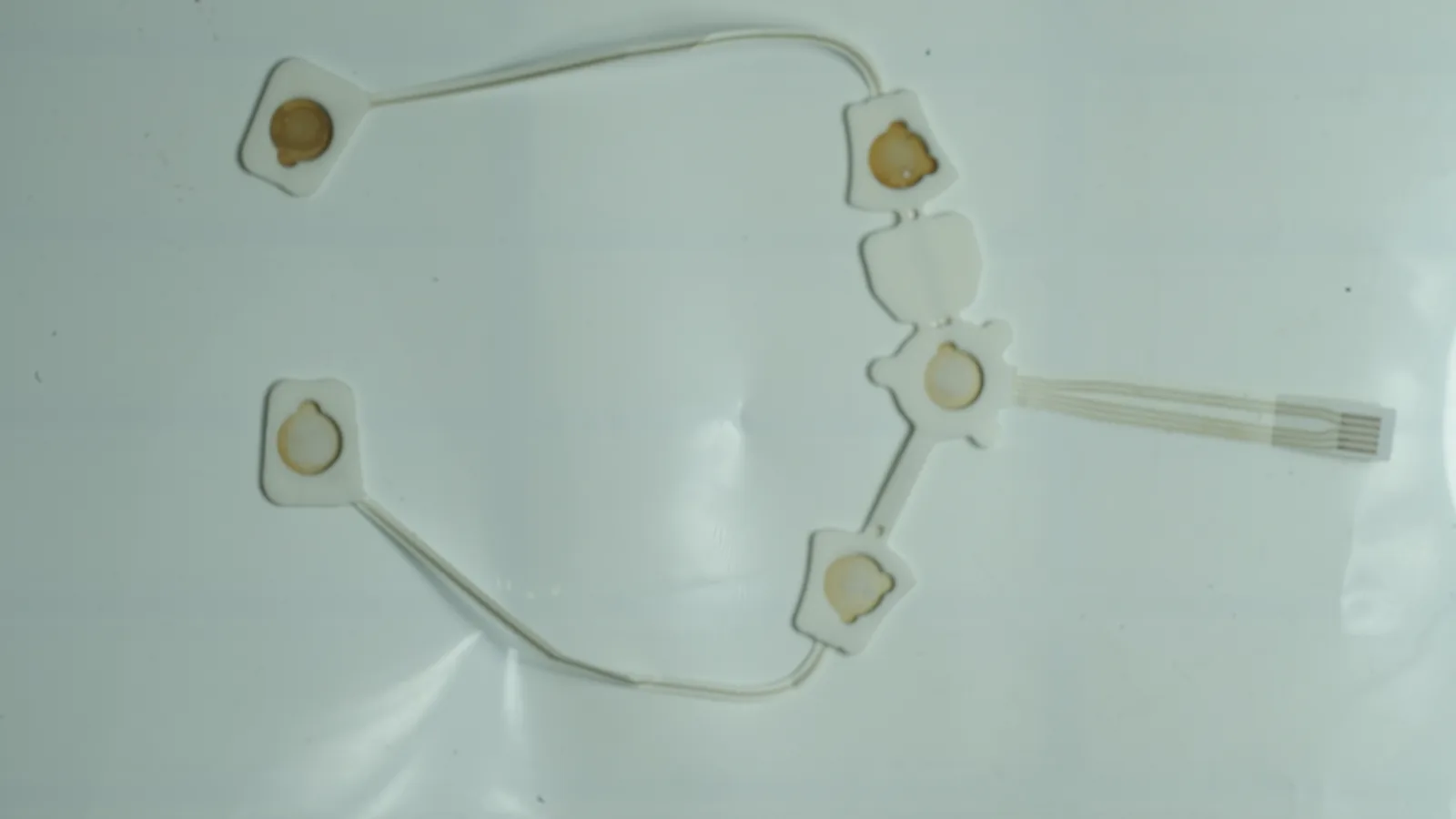
Compare PET vs TPU electrode substrate choices for printed electrodes by stretch, dimensional stability, cure, ink adhesion, converting, and patch assembly.
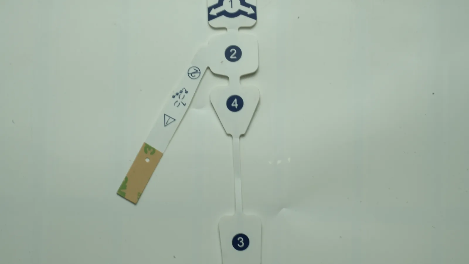
Compare hydrogel vs dry electrode adhesive across 8 OEM factors: impedance, tack, wear, residue, storage, converting, packaging, and validation.
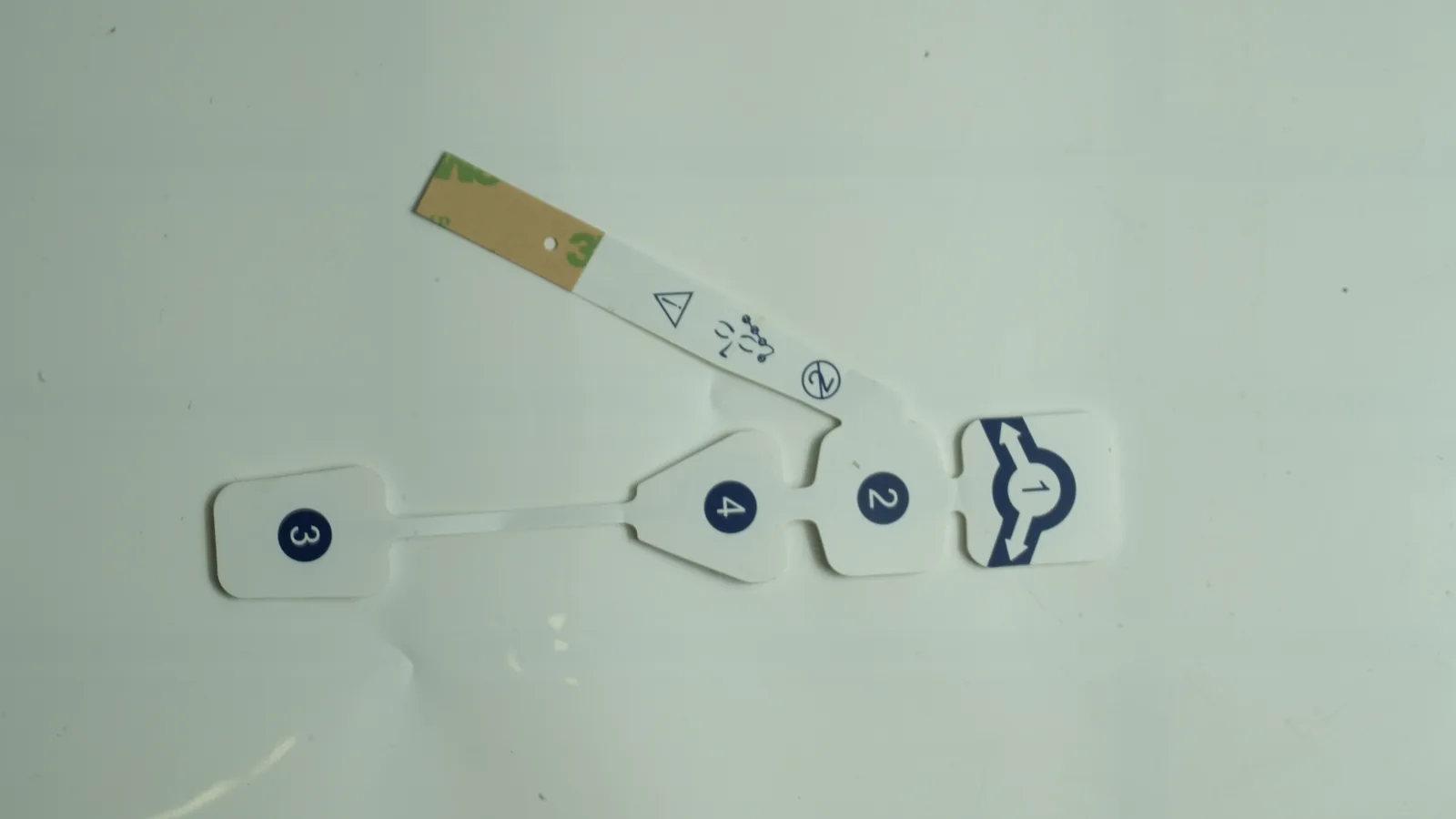
Compare 4 electrode pad connector types—snap, tab, lead wire, and printed tail—by mating interface, strain relief, packaging, and test boundary.
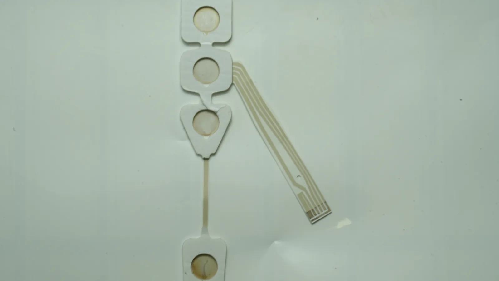
Use this 10-part medical electrode RFQ requirements checklist to prepare drawings, layer artwork, materials, interfaces, tests, packaging, and approvals.
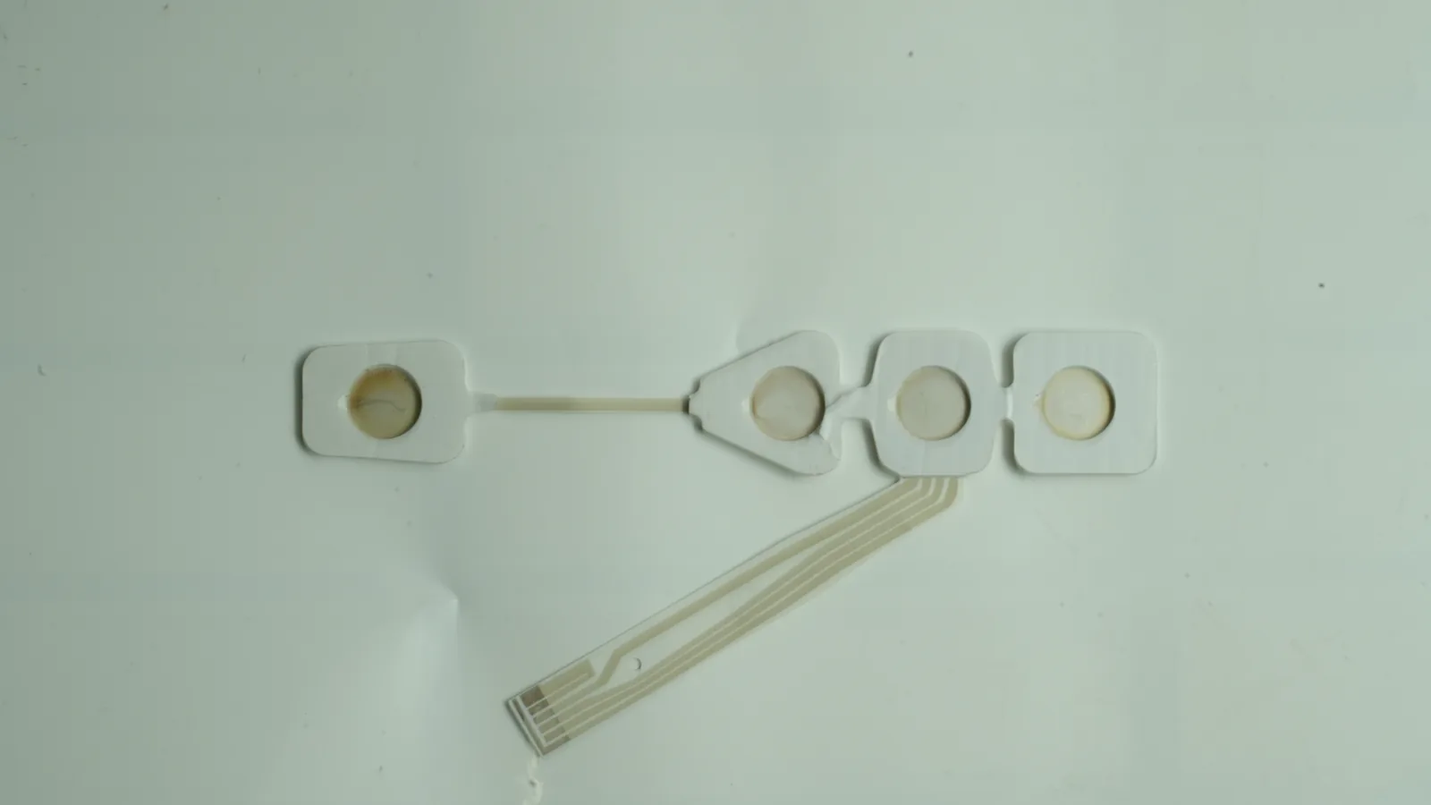
Move an electrode patch prototype to production with seven gates for print trials, sample approval, device validation, pilot controls, and repeat release.
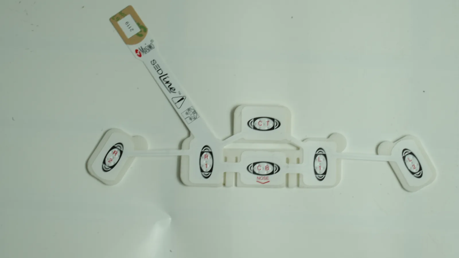
Multi channel printed electrode array design in 10 gates: map geometry, route traces, specify crossovers, dielectric, tail, connector, and inspection.
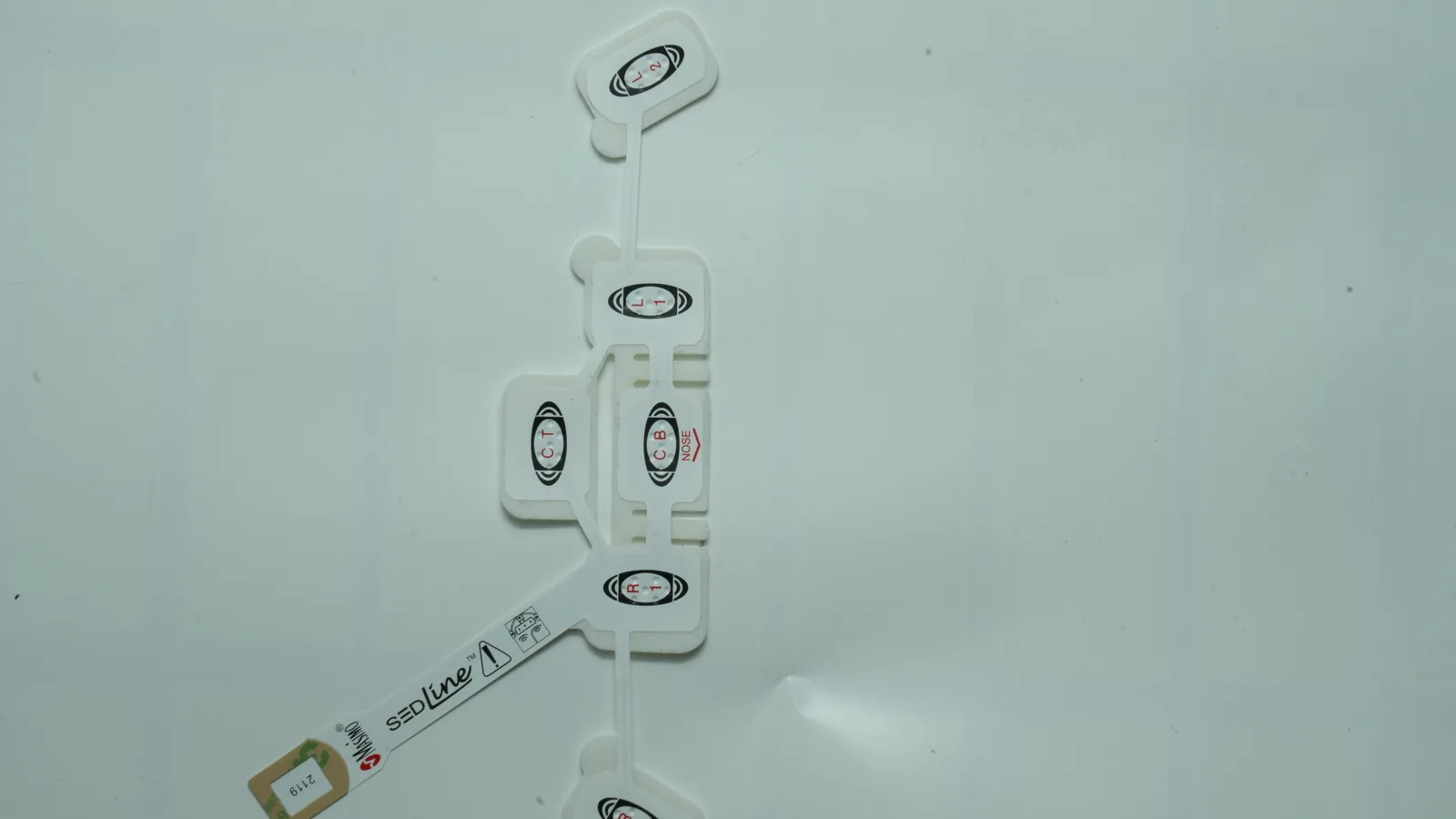
Use this 10-input ECG electrode patch design guide to define geometry, skin interface, connections, packaging, and finished-device validation boundaries.
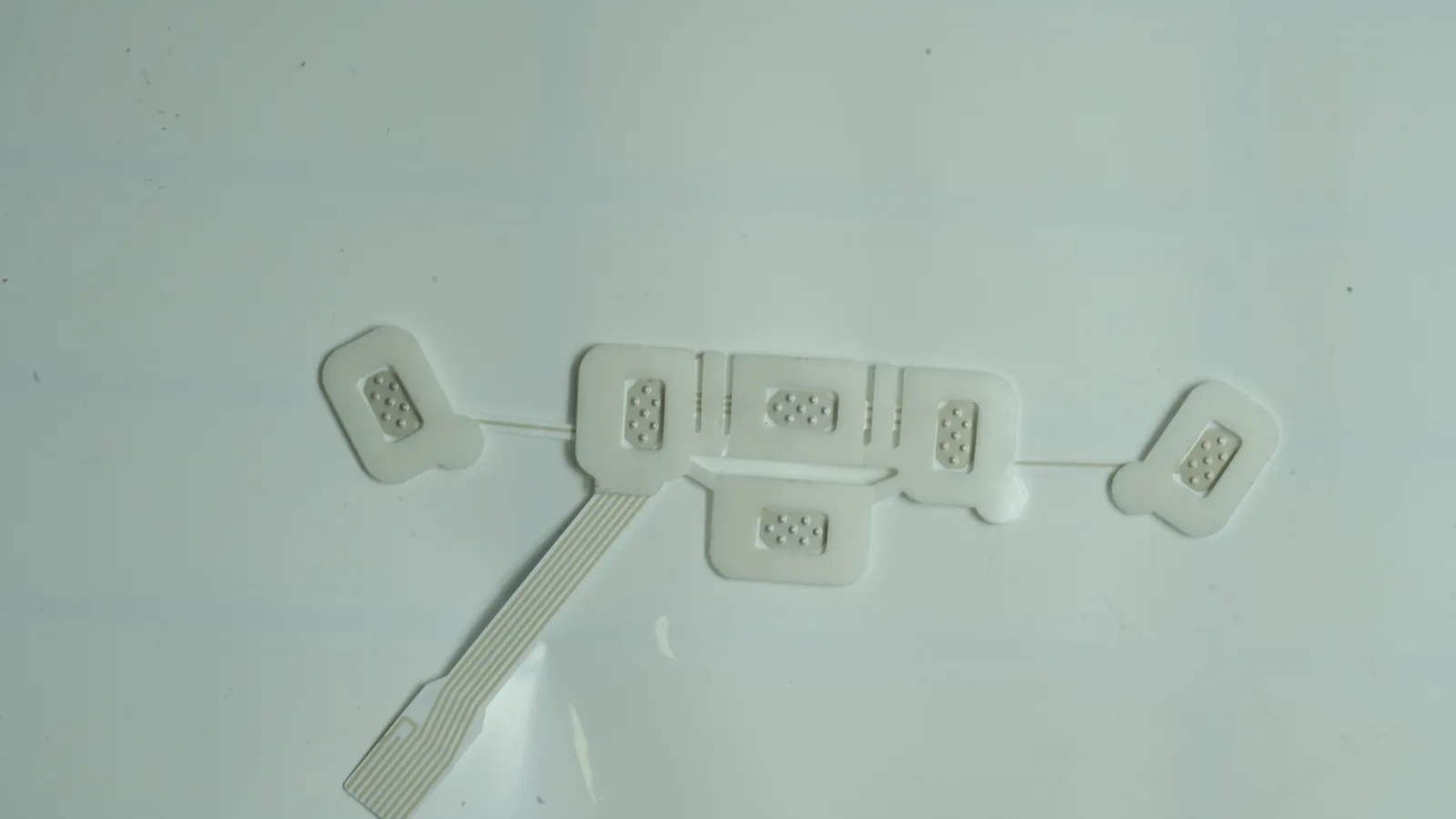
EEG electrode array design guide with 10 criteria for scalp geometry, channel maps, printed routing, connectors, wear conditions, and OEM validation.
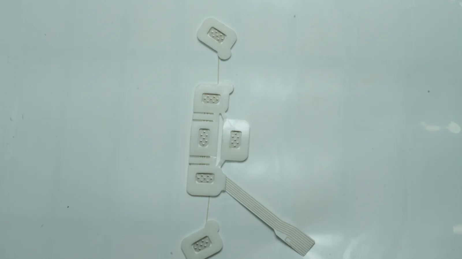
Plan a surface EMG electrode layout using 10 engineering checks for spacing, orientation, printed traces, motion, connectors, and system validation.
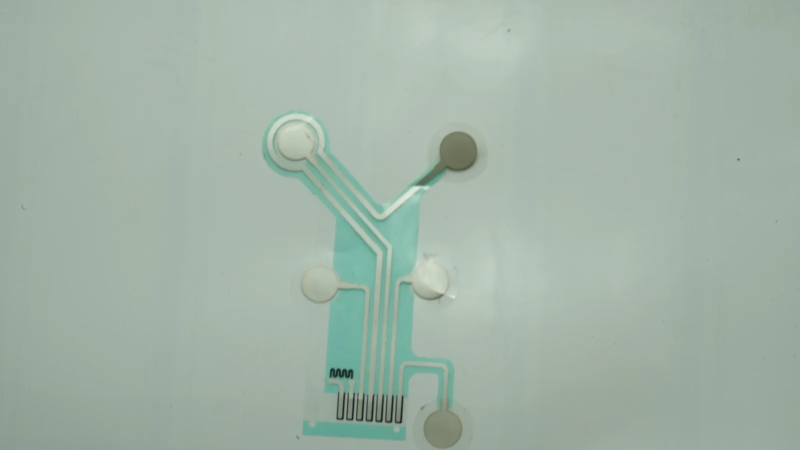
TENS electrode pad design guide covering 9 geometry criteria, current distribution, hydrogel, lead attachment, edge effects, and validation.

Electrosurgical grounding pad design guide covering 10 boundaries for conductors, hydrogel, CQM interfaces, packaging, and validation ownership.
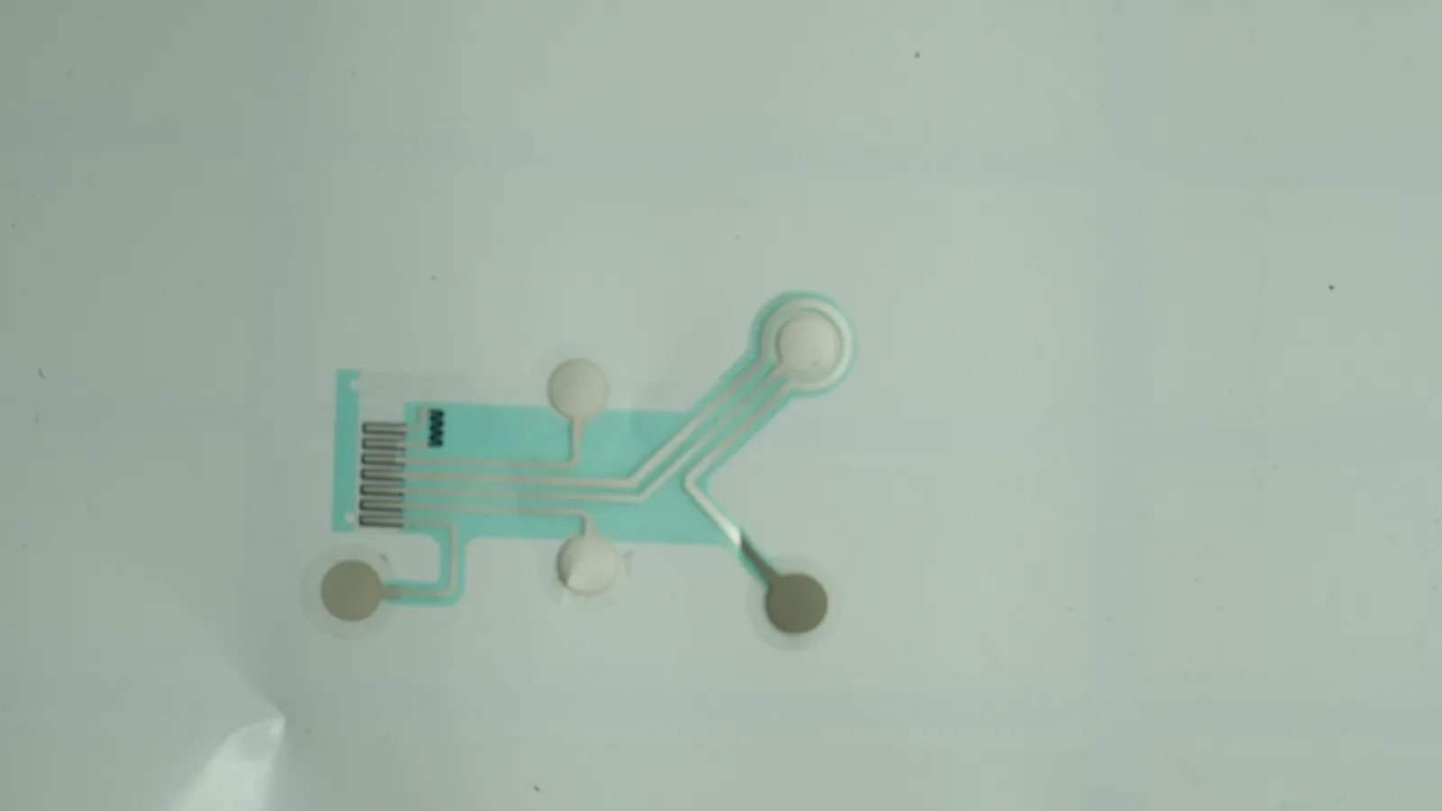
Plan wearable biosensor electrode patch design in 8 decisions: skin interface, printed electrodes, interconnects, encapsulation, testing, and packaging.