
Human factors HMI requirements turn operator capabilities, tasks, protective equipment and working conditions into testable front-panel specifications. They apply to the display, touch sensor, overlay, physical controls, circuit, bezel and enclosure interface—not only to screen graphics. Define the intended users and critical tasks first; then specify reach, sightlines, character angle, touch-target geometry, actuation force, feedback, contrast, grouping, error recovery and workload acceptance. Verify those requirements on the assembled panel with representative operators, gloves, ambient light, contamination and machine motion. PLC/SCADA programming remains outside JASPER’s manufacturing scope, but the hardware must give the control system a usable, unambiguous physical interface.
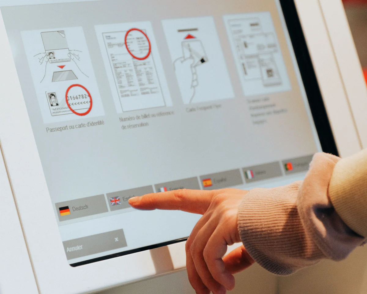
| Decision area | Put this in the requirement | Verify with |
|---|---|---|
| Reach and posture | Operator population, stance, datum, control coordinates, allowable posture | CAD reach study plus representative-user trial |
| Viewing | Eye-point range, distance, vertical/horizontal sightlines, allowable obliquity | Full-size panel at extreme eye points |
| Gloves and touch | Glove material/thickness, target size/gap, touch mode, moisture state | Exact glove and complete sensor/overlay stack |
| Feedback | Force-travel limits, tactile ratio or alternate confirmation, indicator behavior | Force-displacement data and task observation |
| Contrast and optics | Ambient illuminance, view cone, glyph height, contrast, haze/transmittance | Assembled optical measurement |
| Error control | Critical-action guard, confirmation, cancel/recovery path, state indication | Nominal, time-pressured and degraded task trials |
HMI ergonomics is a system property, not a screen-style preference
An ergonomic human machine interface lets specified users complete specified tasks effectively, efficiently and with acceptable satisfaction in the intended context of use. That framing follows ISO 9241-11:2018; it prevents a design team from calling a panel “ergonomic” because it looks clean on a desktop monitor.
The physical interface is a stack. A typical assembly includes the graphic overlay or cover lens, printed legends and windows, touch sensor, display, spacer or adhesive layers, physical keys or domes, printed circuit or flex tail, bezel, gasket and enclosure cutout. Each layer can change what the operator sees or feels. For foundational hardware terminology, see What Is an HMI Panel? Hardware and OEM Guide.
JASPER’s HMI assemblies cover this front-panel hardware and its mechanical/electrical interfaces. Control logic, alarm philosophy, PLC tags and SCADA navigation remain the OEM or system integrator’s responsibility.
Operator, task and environment data must exist before panel dimensions
Good HMI geometry starts with a context-of-use record, not an average body. NIOSH reports that general-worker anthropometric data are limited and that occupational groups differ materially; one convenient dataset cannot represent every workforce (NIOSH, 2024). ISO 14738:2002 provides principles for applying anthropometric measurements to sitting and standing workstations at non-mobile machinery, while its official scope excludes maintenance, repair and cleaning space. Those activities need separate scenarios.
Record, at minimum:
- intended operators and maintainers, including accommodation needs;
- standing, seated, mobile or constrained posture for each task;
- required PPE, especially glove, face-shield and eye-protection details;
- normal, startup, setup, fault recovery, cleaning and maintenance tasks;
- task frequency, required response time and consequence of a wrong action;
- ambient light, glare sources, temperature, moisture, dust, chemicals and vibration;
- mounting height, panel tilt, approach direction and enclosure obstructions.
The result is a set of test conditions. “Usable with gloves” is not one. “Complete the reset-and-restart task using the specified cut-resistant glove, on a wet panel, without adjacent-target activation” can be observed and accepted or rejected.
Reach and viewing geometry become drawing datums and sightline limits
Reach requirements should name a body reference, panel datum and control coordinates. Put frequent or time-critical controls inside the project’s validated primary reach envelope. Place infrequent controls farther away only when the posture remains acceptable. Check the shortest intended operator in the least favorable stance for reach, and the largest intended operator for clearance, occlusion and accidental contact. Do not use a single percentile label as a substitute for the underlying population and task.
Viewing requirements need the same discipline. Define the nearest and farthest eye points, then draw lines from those points to the center and corners of the active display. Record horizontal and vertical viewing angles relative to the display normal. The display specification must preserve required luminance, contrast and color-state discrimination across that entire cone and at the operating-temperature extremes; the vendor’s headline “viewing angle” is not enough if its measurement criterion differs from the project requirement.
Test the extremes.
The NASA Human Integration Design Handbook defines the visual-angle geometry used to tie character height to viewing distance:
H = 2D × tan(α/2)
Here, H is visible uppercase character height, D is eye-to-display distance and α is visual angle. NASA’s crew-display standard requires at least 0.25° and prefers 0.4° or more; that is a spaceflight requirement, not a universal industrial rule, but it is a useful, traceable calculation method (NASA Appendix F).
| Farthest viewing distance | Height at 0.25° | Height at 0.4° |
|---|---|---|
| 600 mm | 2.62 mm | 4.19 mm |
| 800 mm | 3.49 mm | 5.59 mm |
Use the rendered glyph, not nominal point size. Recheck with required eyewear, ambient light, vibration and off-axis viewing.
Touch targets and physical keys must be sized for the actual hand condition
Touch-target dimensions are task and user variables, not a pixel convention. In a 2018 controlled study of 20 participants performing digit and letter entry, square buttons 17.5 mm and larger performed better than smaller candidates; the tested sizes were 7.5–27.5 mm with 0, 1 or 3 mm gaps (International Journal of Industrial Ergonomics). That result is a prototype starting point, not proof that 17.5 mm passes a standing, gloved, vibrating industrial application.
Inclusive testing can change the answer. Sesto and colleagues tested 52 people—with fine motor-control disability, gross motor-control disability or no disability—using 10–30 mm buttons and 1 or 3 mm spacing in a digit-entry task. Button size affected touch forces, impulses and dwell times, and the groups behaved differently (Human Factors, 2012). The engineering implication is direct: evaluate misses, wrong activations and completion time with the intended population instead of copying a consumer UI minimum.
Glove compatibility belongs to the complete electrical and optical stack. One Microchip mXT2952T2 controller datasheet specifies multi-finger glove touch up to 1.5 mm and single-touch operation with various glove materials up to 5 mm, while also making performance subject to configuration, sensor design and stack-up. Those figures apply to that controller, not projected-capacitive touch as a category. Qualify the exact controller firmware, sensor, cover lens or overlay, adhesive or air gap, glove material, moisture state and grounding arrangement.
When touch precision cannot be demonstrated, use larger targets, separate adjacent hazardous actions, add a physical guard or choose a physical control. A physical key drawing should specify cap or embossed area, center spacing, operating force range, travel, actuation point, return behavior and off-center actuation condition.
Feedback and grouping must expose state and resist slips
Every action needs confirmation that is distinguishable from mere finger contact. A touchscreen can change appearance after a valid input; a membrane key can provide tactile snap; the controller can drive a lamp or sounder after the commanded state is accepted. For a metal dome, capture the force-displacement curve. Trip force, release force, travel and tactile ratio reveal more than a single nominal actuation-force value; the Snaptron force-displacement guide defines tactile ratio as (Fmax − Fmin) / Fmax × 100 for its dome measurements.
Group controls by task sequence and function. Separate commands that produce opposing or hazardous outcomes. Use shape, position, legend and state indication so color is redundant rather than the only code. The rail-specific requirements in 49 CFR Appendix E are a useful benchmark: they call for controls arranged by expected order of use, similar controls grouped together, timely feedback and easy recovery from error. They are legally scoped to covered U.S. rail systems, so other machinery still needs its own risk assessment.
Emergency-stop design is not a touchscreen-layout decision. ISO 13850:2015 defines separate principles for the machinery emergency-stop function. Do not replace a required emergency device with an ordinary soft key. See High-Performance HMI Hardware Design for the complementary hardware hierarchy.
Contrast and overlay optics must be measured on the assembled interface
Display readability depends on the combined display, touch sensor, cover material, printed window, surface texture, adhesive, bezel and ambient reflections. Measure the assembly at the required ambient illuminance, view angles, brightness settings and temperatures. A display-module datasheet measured without the production overlay does not close the requirement.
Specify visible glyph height, foreground/background luminance or luminance contrast, color-state discrimination, allowable reflections and the required view cone. As a scoped benchmark, 49 CFR Appendix E requires covered rail displays to provide at least 35 cd/m² foreground/background luminance difference, a minimum 3:1 contrast and 7:1 preferred. These values should not be pasted into unrelated equipment specifications without considering ambient light, risk and the applicable product standard.
For transparent plastic windows, ASTM D1003-21 covers haze and luminous-transmittance measurement. Use it when those properties control readability, and name specimen construction and conditioning. Also inspect printed edge registration, adhesive encroachment, Newton rings or air-gap artifacts, bezel shadowing and surface damage after cleaning exposure. An enclosure IP code under IEC 60529 classifies protection of the tested enclosure; it does not automatically transfer from a component film to an untested panel assembly.
Error recovery and workload requirements belong in the hardware brief
Error-resistant hardware makes the intended action obvious, blocks or separates dangerous alternatives and shows what happened after actuation. ISO 9241-110:2020 names conformity with user expectations, controllability and use-error robustness among its interaction principles. Hardware can support those principles through stable key locations, distinct shapes, guarded controls, readable state legends and enough display area for instructions and recovery choices.
Measure the task, not the panel’s appearance. Record completion time, wrong-control activations, missed touches, repeated presses, recovery success and requests for assistance. NASA-TLX can add a structured subjective workload measure across mental, physical and temporal demand, performance, effort and frustration (NASA TLX); use it consistently and keep objective error data beside it.
The OEM owns software sequences and state logic. The hardware team must still reserve the right controls, indicators, active display area and feedback channels early enough to avoid a late enclosure change. That boundary is developed further in HMI Hardware Development Process for OEM Equipment.
A hardware failure chain shows where an operator error really begins
| Design miss | Physical effect | Operator effect | System risk | Drawing or test control |
|---|---|---|---|---|
| Target gap collapses after bezel tolerance | Adjacent active areas crowd | Wrong target activates | Unintended command | Worst-case active-area and bezel stack drawing |
| Thick glove is not included in tuning | Touch signal falls below threshold | Repeated presses or no response | Delay during fault recovery | Exact-glove wet/dry acceptance trial |
| Overlay window adds haze and reflection | Contrast falls off-axis | State is misread | Incorrect diagnosis | Assembly haze, luminance and view-cone test |
| Dome actuator is off-center | Force curve and snap degrade | Confirmation feels inconsistent | Double actuation | Actuator/dome concentricity and force-displacement limits |
| Frequent key is outside primary reach | Shoulder or trunk excursion rises | Fatigue and slower response | Workaround or missed action | Reach-envelope review with installed enclosure |
| Critical control resembles routine controls | Identification depends on memory | Selection slip | Hazardous command | Separation, guard, shape and redundant coding |
Human factors HMI requirements need a design-input matrix
The matrix below is suitable for a drawing review or RFQ kickoff. Values must be filled from the project’s context of use; blanks are unresolved engineering inputs, not supplier discretion.
| Input | Required unit or definition | Drawing / RFQ output | Acceptance evidence |
|---|---|---|---|
| Operator population | Named dataset, roles, accommodations | Eye points, reach envelopes, clearances | CAD record and participant profile |
| Mounting geometry | mm and degrees from machine datums | Panel height, tilt, approach direction | Installed mockup measurement |
| Viewing | mm distance; horizontal/vertical degrees | Active area, glyph-height minimum, view cone | Extreme-eye-point readability test |
| Ambient light | lux and glare-source direction | Display luminance/contrast requirement, surface finish | Metered light setup and photos |
| Touch targets | mm active width/height and edge gap | Artwork plus touch-map tolerance | Miss/wrong-activation rate by task |
| Gloves | Material, coating, thickness, size, wet/dry state | Touch mode and physical-control alternatives | Exact-PPE task trial |
| Physical keys | N force, mm travel, Fmax/Fmin, cycles if required | Dome/switch, actuator and emboss stack | Force-displacement and endurance plan |
| Feedback | Visual, tactile and/or audible event | Indicator, dome, light guide or sounder interface | Action-to-confirmation observation |
| Overlay optics | Haze %, transmittance %, finish, window registration | Material/print/adhesive window specification | ASTM D1003 where applicable plus assembly inspection |
| Environment | Temperature, humidity, fluids, dust, vibration | Material, seal, vent and connector requirements | Applicable assembly-level test report |
| Error control | Critical actions and recovery path | Guard, spacing, confirmation and cancel provisions | Scenario-based error/recovery test |
| Interfaces | Tail exit, connector, keep-outs, grounding, enclosure cutout | Controlled interface drawing | First-article fit and electrical test |
Use the HMI Panel Assembly Design Checklist to carry these inputs into the mechanical package.
Validation must use an assembled panel and representative tasks
Validate progressively: full-scale layout, functional prototype, installed preproduction assembly and production-representative sample. ISO 9241-210:2019 covers human-centered design activities across the lifecycle and applies to both hardware and software components; waiting until final software integration defeats that iteration loop.
A practical protocol includes:
- Freeze operator profiles, PPE, task scripts and environmental setups.
- Measure reach, sightlines, glyph height, target geometry and control force before the trial.
- Run normal, time-pressured, fault-recovery and degraded-display/touch scenarios.
- Record completion time, misses, wrong activations, repeated inputs, recovery and subjective workload.
- Repeat after cleaning exposure, temperature conditioning or vibration when those conditions can change the interface.
- Convert failures into artwork, stack-up, material, controller or enclosure revisions; then retest the affected tasks.
Tie the acceptance matrix to testing and validation planning and use prototyping and sample approval to freeze the approved tactile, optical and dimensional reference. A golden sample without its measured conditions is only a visual sample.
General ergonomic guidance is insufficient for some equipment
Use a qualified human-factors and safety team when an interface controls safety functions, hazardous motion, explosive atmospheres, transportation, medical treatment, nuclear processes or another regulated application. Product-specific law and Type-C machinery standards can override general guidance. The same caution applies when operators have unusual reach constraints, severe vibration, extreme PPE or consequences that make one erroneous actuation unacceptable.
Frequently Asked Questions
What are human factors HMI requirements?
Human factors HMI requirements are measurable design inputs that connect specified operators and tasks to interface geometry and performance. They cover reach, viewing, target size, control force, feedback, contrast, grouping, recovery and workload under named environmental and PPE conditions. Each requirement needs a drawing field or test method.
Is there one correct mounting height and angle for an industrial HMI?
No. Mounting height and angle depend on the intended population, standing or seated posture, approach direction, viewing distance, enclosure geometry and task frequency. Define extreme eye and reach points in the machine coordinate system, then verify the installed panel with representative operators instead of copying an average height.
What touchscreen button size should an HMI use with gloves?
There is no universal glove target size. A controlled ungloved study found better performance at 17.5 mm and above for its digit/letter tasks, but industrial acceptance must use the exact glove, stack, posture, moisture and motion. Start with evidence-informed candidates, then set the final millimeter dimensions from task-test results.
Can projected-capacitive touch work through thick industrial gloves?
Some controllers can, under specified conditions. Microchip’s mXT2952T2 lists multi-finger operation through gloves up to 1.5 mm and single-touch with various materials up to 5 mm, subject to configuration and stack design. Treat that as model-specific data and test the complete production sensor, overlay, glove and grounding arrangement.
How should physical-key feedback be specified?
Specify operating force range, travel, actuation point, release force, tactile ratio when applicable, actuator alignment and the test plunger or finger condition. Add visual or audible confirmation when task risk requires it. A nominal force alone cannot describe off-center feel, return behavior or the assembled overlay’s effect.
What contrast ratio is required for an industrial HMI display?
No single contrast ratio covers all industrial equipment. Define ambient illumination, glare, viewing cone, temperature and critical information first. The U.S. rail rule in 49 CFR Appendix E uses 3:1 minimum and 7:1 preferred for its covered displays, but those scoped values are a benchmark, not universal compliance criteria.
How can an OEM measure HMI operator workload?
Use representative task scenarios and collect objective completion time, wrong activations, misses, repeated inputs, recovery success and assistance requests. NASA-TLX can add consistent subjective ratings for mental, physical and temporal demand, performance, effort and frustration. Compare design variants under the same users, training, PPE and environment.
What belongs in an HMI ergonomics RFQ?
Include the front-panel drawing, display and touch stack, operator and maintainer profiles, mounting geometry, PPE, task list, environment, key force/travel limits, optical criteria, interface pinout, acceptance tests and annual volume. Identify safety-critical actions and applicable product standards rather than asking the supplier to infer them.
Project-input checklist and engineering handoff
Before release, provide the display size and datasheet, front-panel and enclosure drawings, interface stack, operator/PPE definition, use environment, task-based acceptance matrix and annual volume. Also identify the critical controls, required feedback channels, connector and tail constraints, cleaning agents and applicable regulatory or product standards.
OEM teams can send drawings for engineering review to resolve stack-up, artwork, circuit and enclosure-interface questions. When the inputs are controlled, request an engineering quote for the HMI hardware assembly.
References
- ISO 9241-11:2018, Usability: Definitions and concepts
- ISO 9241-210:2019, Human-centred design for interactive systems
- ISO 9241-110:2020, Interaction principles
- ISO 14738:2002, Anthropometric requirements for workstations at machinery
- ISO 12100:2010, Machinery risk assessment and risk reduction
- ISO 13850:2015, Emergency-stop function
- 49 CFR Appendix E to Part 236, HMI Design
- NUREG-0700 Revision 4, Human-System Interface Design Review Guidelines
- NIOSH, Anthropometry and Work
- NASA Appendix F, Display Standard
- NASA Task Load Index
- Sesto et al., Human Factors 54(3), 2012
- Wang et al., International Journal of Industrial Ergonomics 64, 2018
- Microchip mXT2952T2 Datasheet, Revision 1.1
- ASTM D1003-21, Haze and Luminous Transmittance of Transparent Plastics
- IEC 60529, Degrees of Protection Provided by Enclosures
- NASA Human Integration Design Handbook, Revision 1
- Snaptron, How to Analyze a Force-Displacement Curve for a Dome Switch
Bring the drawing, stack and operating conditions
JASPER engineering will review the interfaces, open risks and evidence required for a production quote.