Dongguan, Guangdong 523927, China[email protected]+86 136 3262 5290
Home / Products / Custom Medical Electrode Pads and Printed Electrode Patches
PRINTED CIRCUITS FOR OEM ELECTRODE PRODUCTS

Custom Medical Electrode Pads and Printed Electrode Patches

Family of custom printed medical electrode pads and flexible electrode arrays

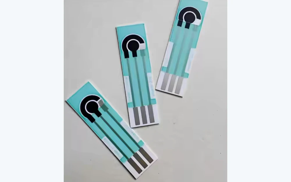
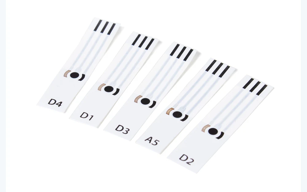
JASPER manufactures custom printed electrode circuits and converted patch assemblies when the functional geometry can be built with printed conductive traces. Projects may combine flexible substrates, electrode sites, insulation, tails, connectors, project-specified adhesive or hydrogel, foam or nonwoven layers, liners, die cuts, packaging, and agreed inspection. The finished medical device, clinical use, signal interpretation, treatment settings, and regulatory validation remain with the OEM.

Family of custom printed medical electrode pads and flexible electrode arrays
7 printed routesECG or EKG, EEG, EMG, stimulation, grounding-pattern, wearable, and custom arrays
Circuit plus convertingprinted geometry, flexible tail, adhesive stack, die cutting, lamination, and packaging
OEM validation stays visiblematerials, electrical acceptance, use conditions, device claims, and regulatory ownership are released

Medical Electrode Pad Products

Choose the route by electrode geometry, printed circuit, connection method, converted material stack, customer handoff, and validation owner.

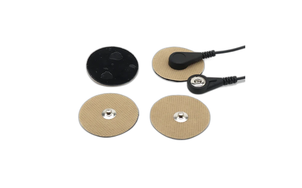
ECG and EKG Electrode Patches
PRINTED ELECTRODE ROUTE

ECG and EKG Electrode Patches

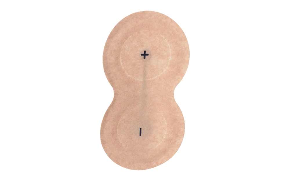
Printed single-site or connected patch constructions with released contact geometry, snap, tab or tail interface, backing, adhesive or hydrogel zones, liner, and packaging.

Choose it when: the OEM needs a custom patch format or circuit interface around an ECG or EKG acquisition design

View ECG and EKG Electrode Patches
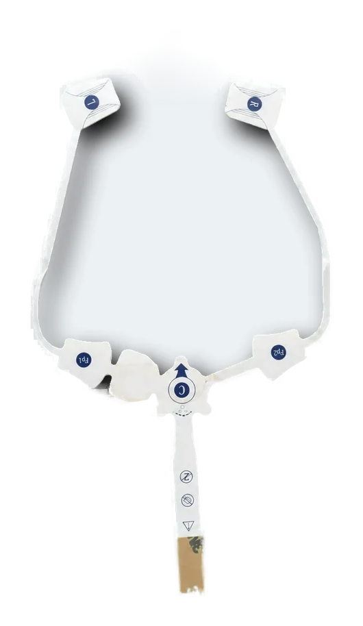
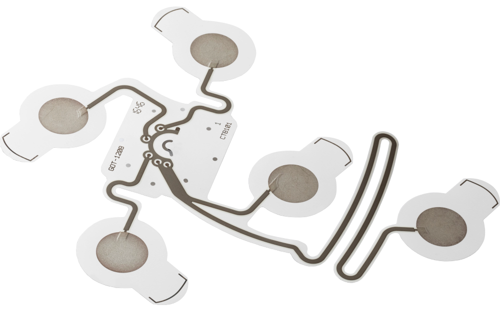
EEG Electrode Arrays
PRINTED ELECTRODE ROUTE

EEG Electrode Arrays

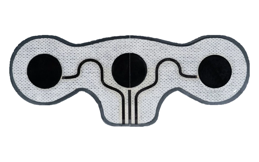
Flexible multi-site arrays coordinating electrode positions, channel identity, printed routing, reference locations, tail, connector, converted layers, and registration.

Choose it when: several scalp-contact sites must remain positioned and connected as one repeatable array

View EEG Electrode Arrays
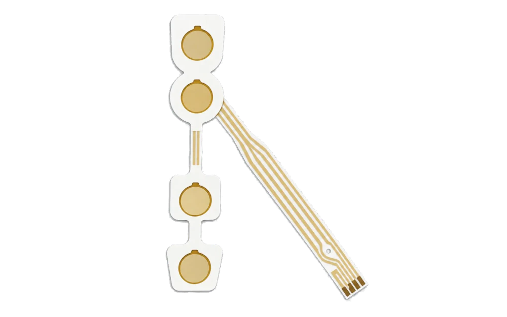
EMG Electrodes
PRINTED ELECTRODE ROUTE

EMG Electrodes

Paired or multi-site printed electrode layouts with controlled spacing, reference geometry, flexible routing, connector handoff, backing, adhesive zones, and packaging.

Choose it when: the acquisition layout depends on fixed differential spacing and one controlled flexible assembly

View EMG Electrodes
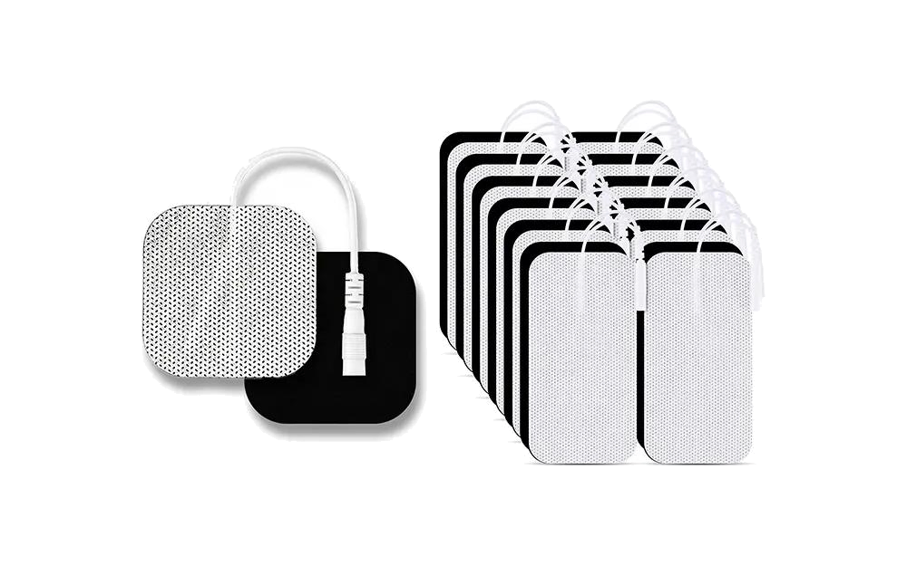
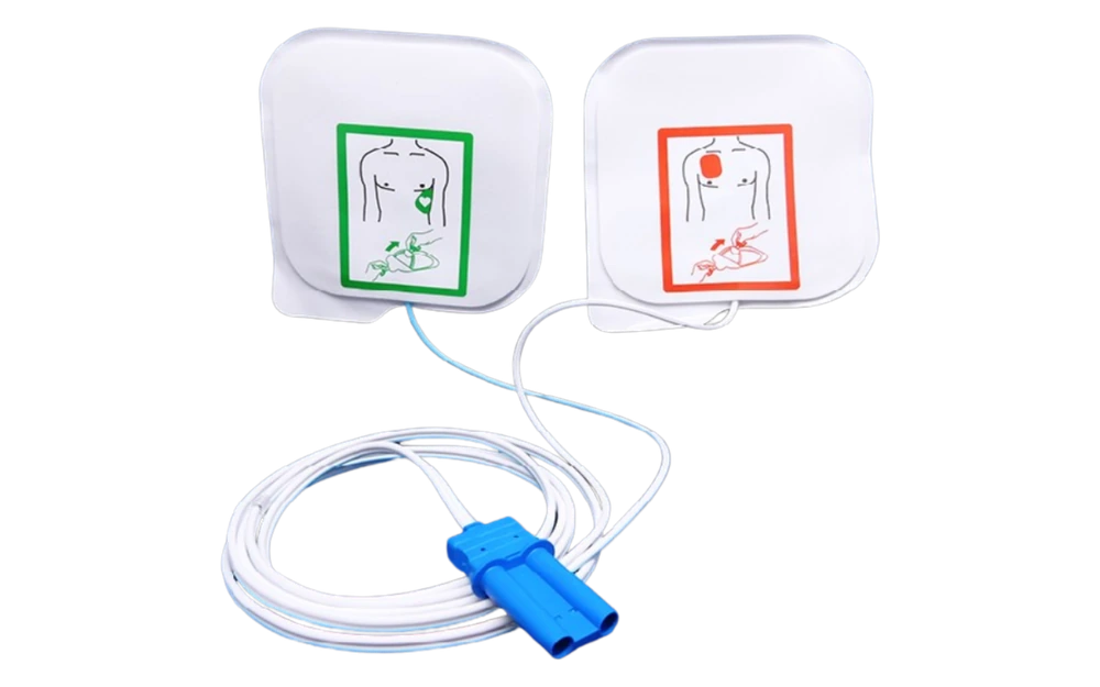
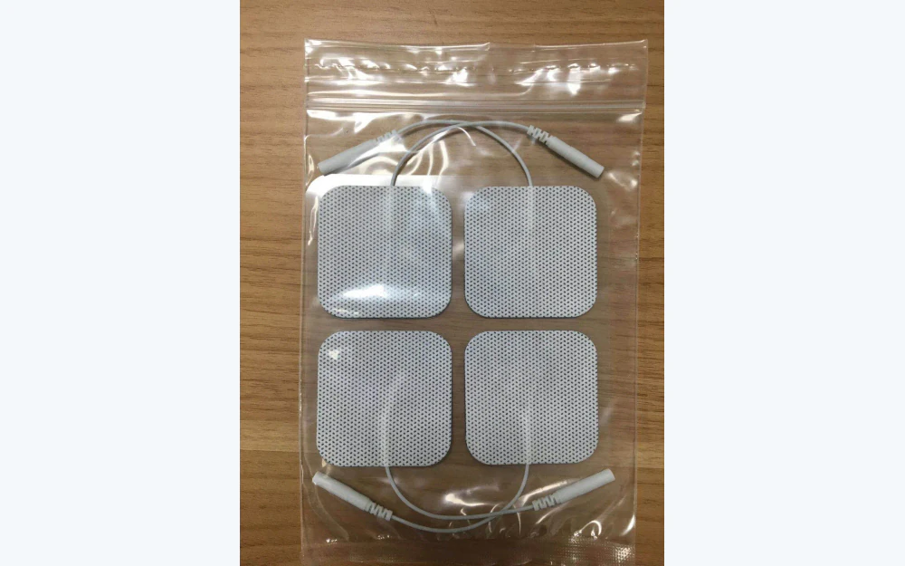
TENS, EMS, and NMES Electrode Pads
PRINTED ELECTRODE ROUTE

TENS, EMS, and NMES Electrode Pads

Custom printed conductive areas and lead interfaces converted with project-specified backing, adhesive or hydrogel, liner, edge geometry, packaging, and inspection.

Choose it when: a stimulation-device OEM owns the waveform and validation but needs a custom manufacturable pad construction

View TENS, EMS, and NMES Electrode Pads
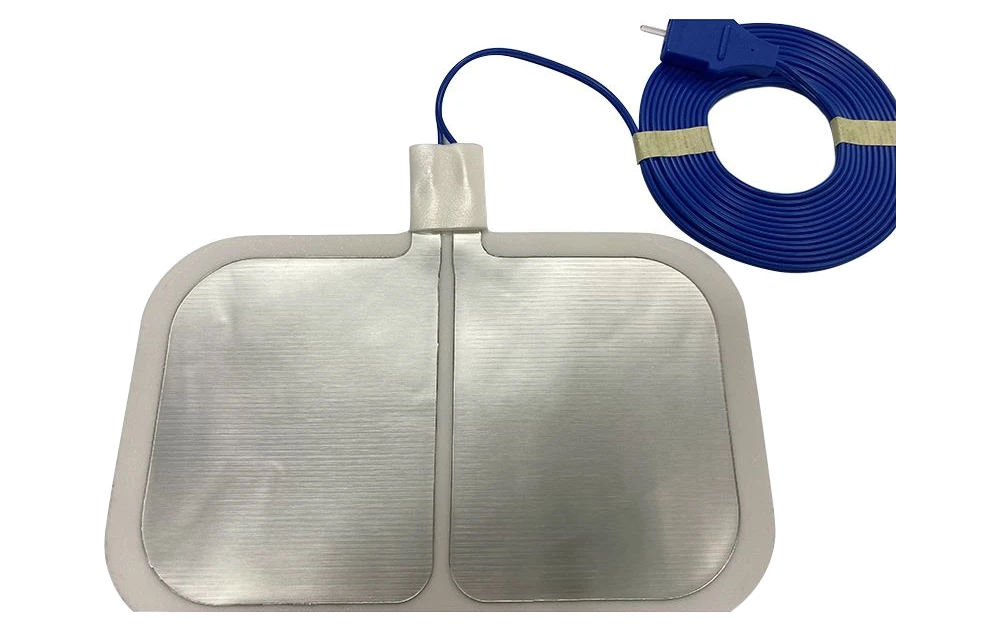
Electrosurgical Grounding Pads
PRINTED ELECTRODE ROUTE

Electrosurgical Grounding Pads

Custom printed conductive patterns and converted return-electrode assembly support produced only to an OEM-released geometry, material stack, interface, and inspection plan.

Choose it when: the buyer needs printed-pattern and converting support while retaining all finished-device safety and compatibility validation

View Electrosurgical Grounding Pads
Wearable Biosensor Patches
PRINTED ELECTRODE ROUTE

Wearable Biosensor Patches

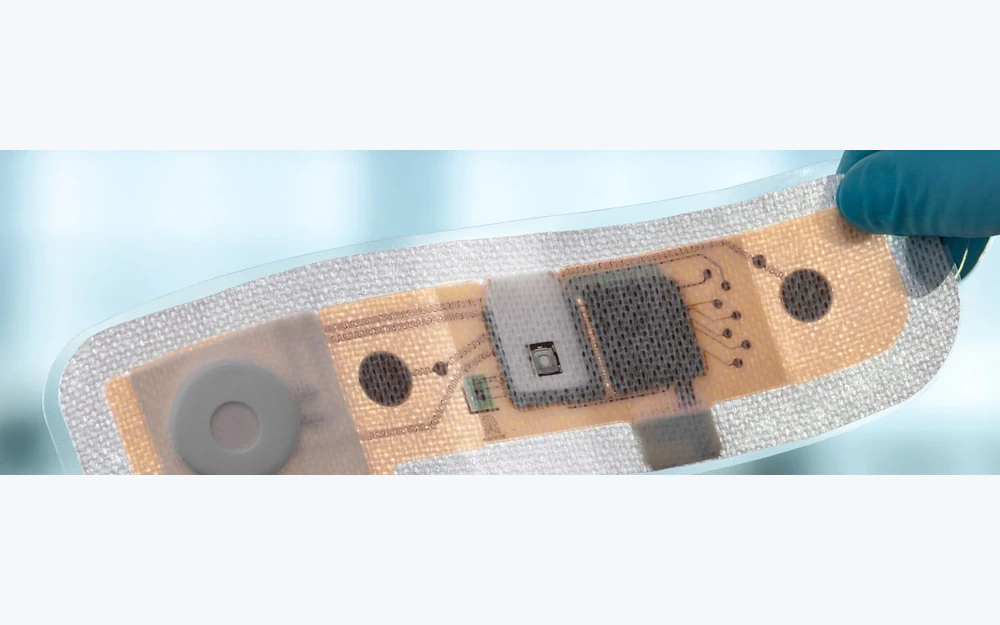
Flexible printed sensing sites, traces, component or connector lands, tail routing, backing, adhesive zones, strain management, liners, and packaged handoff.

Choose it when: a wearable electronics team needs the flexible patch circuit and converted body supplied to its device architecture

View Wearable Biosensor Patches
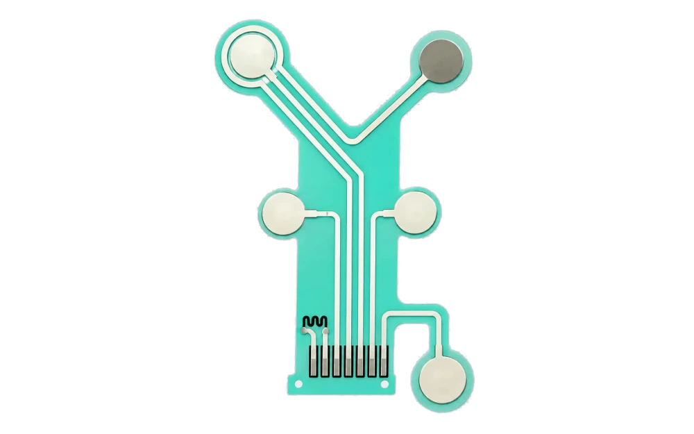
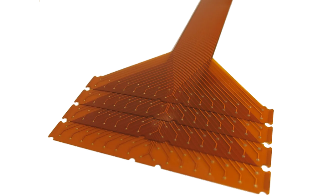
Custom Printed Electrode Arrays
PRINTED ELECTRODE ROUTE

Custom Printed Electrode Arrays

Application-specific electrode sites, conductive traces, dielectric zones, tail and connector geometry, flexible substrates, lamination, die cutting, and agreed electrical inspection.

Choose it when: the project does not fit a standard clinical label and the printed circuit geometry is the primary product

View Custom Printed Electrode Arrays

The Product Is the Released Printed and Converted Construction

Medical electrode pad is a broad purchasing term. A manufacturable release needs the electrode-site geometry, conductive material, trace routing, insulation, substrate, tail, connector or lead attachment, backing, adhesive or hydrogel zones, liner, die-cut outline, packaging state, and inspection boundary.

The printed circuit can be one layer inside a finished patch or the main flexible array supplied to another converter or device assembler. The quotation should say which layers JASPER prints, procures, laminates, die cuts, assembles, inspects, and packages.

Material suitability and electrical acceptance depend on the OEM's intended use, skin-contact plan, duration, signal or stimulation architecture, sterilization or cleanliness strategy, packaging, storage, transport, and regulatory pathway. None of those outcomes should be inferred from a generic material name.

Custom printed electrode manufacturing fits when:

  • the functional conductor, sensing site, return pattern, or interconnect can be produced with printed circuitry
  • electrode positions, trace routes, adhesive zones, tail geometry, and die-cut features require one registered construction
  • project-specific materials and inspection criteria can be released before repeat production
  • the OEM retains finished-device electrical, clinical, biocompatibility, packaging, shelf-life, regulatory, and use validation

Choose the Route by Geometry, Interface, and Validation Owner

The route name helps organize the RFQ. The released construction and customer responsibility matrix determine what is actually manufactured.

Product RouteManufacturing FocusOEM Release Evidence
ECG or EKG patchesSingle-site or connected electrodes, snap or tail interface, backing, adhesive or hydrogel zones, liner, and packageContact geometry, interface, material stack, electrical limits, placement and acquisition validation
EEG arraysMulti-site position, channel routing, reference sites, flexible carrier, tail, connector, and registrationSite map, channel identity, placement fixture, signal chain, cable interface, and array acceptance
EMG electrodesDifferential spacing, paired or multi-site geometry, reference position, routing, connector, and converted stackSpacing datum, acquisition interface, motion conditions, electrical limits, and use validation
TENS, EMS, or NMES padsConductive area, lead interface, edge geometry, backing, adhesive or hydrogel conversion, liner, and packageWaveform, current and thermal limits, placement, treatment logic, reuse policy, and finished-device validation
Grounding-pad patternsOEM-defined printed return pattern, split geometry, lead or connector interface, converted layers, and inspectionSafety architecture, monitoring compatibility, power and thermal limits, contact assessment, and regulatory validation
Wearable patchesSensing sites, flexible circuit, component lands, tail, strain management, backing, adhesive zones, liner, and packageElectronics, firmware, algorithms, wear study, environmental conditions, biocompatibility, and device validation
Custom printed arraysApplication-specific electrode map, traces, dielectric, substrate, tail, connector, lamination, and die cutElectrical test method, mating interface, installation, functional acceptance, and complete product validation
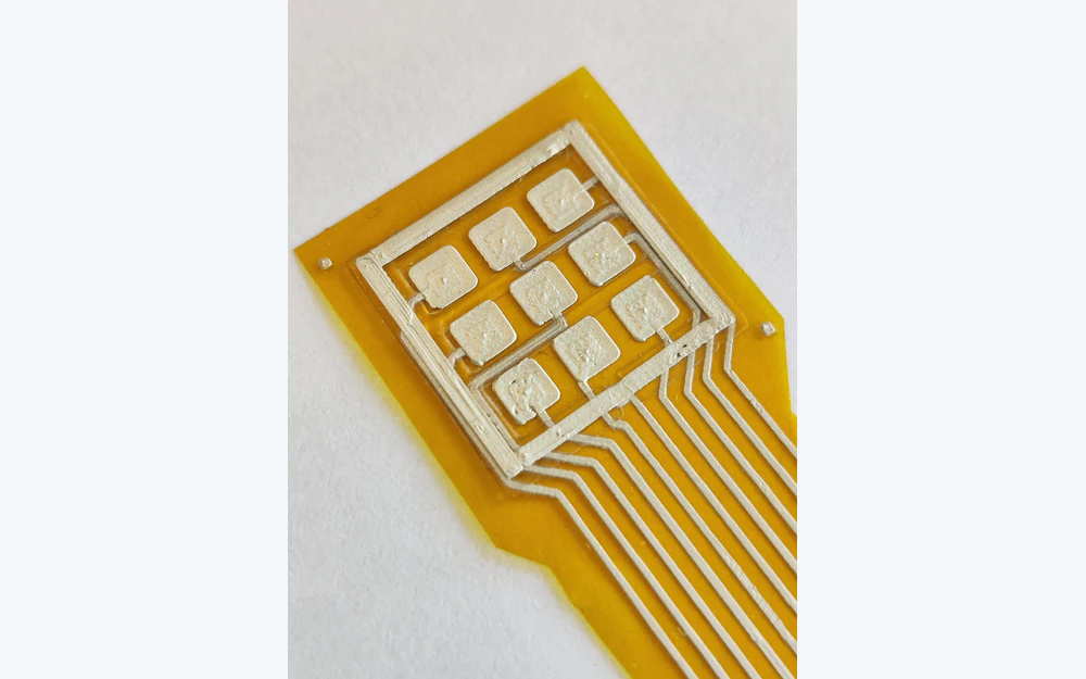
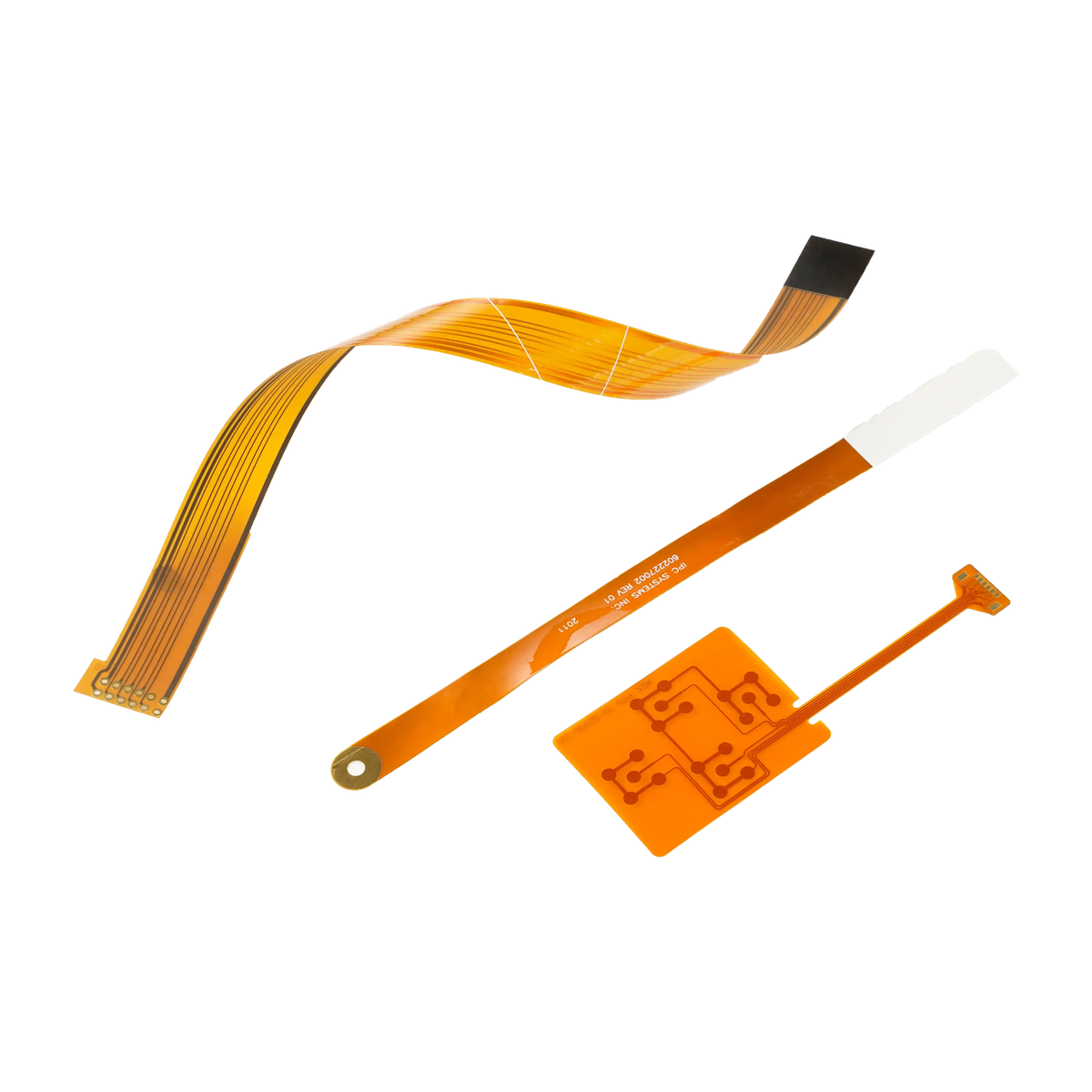
Custom printed electrode array with routed conductive traces and flexible tail
PRINTED FUNCTION

Release Electrode Geometry and Routing as Circuit Data

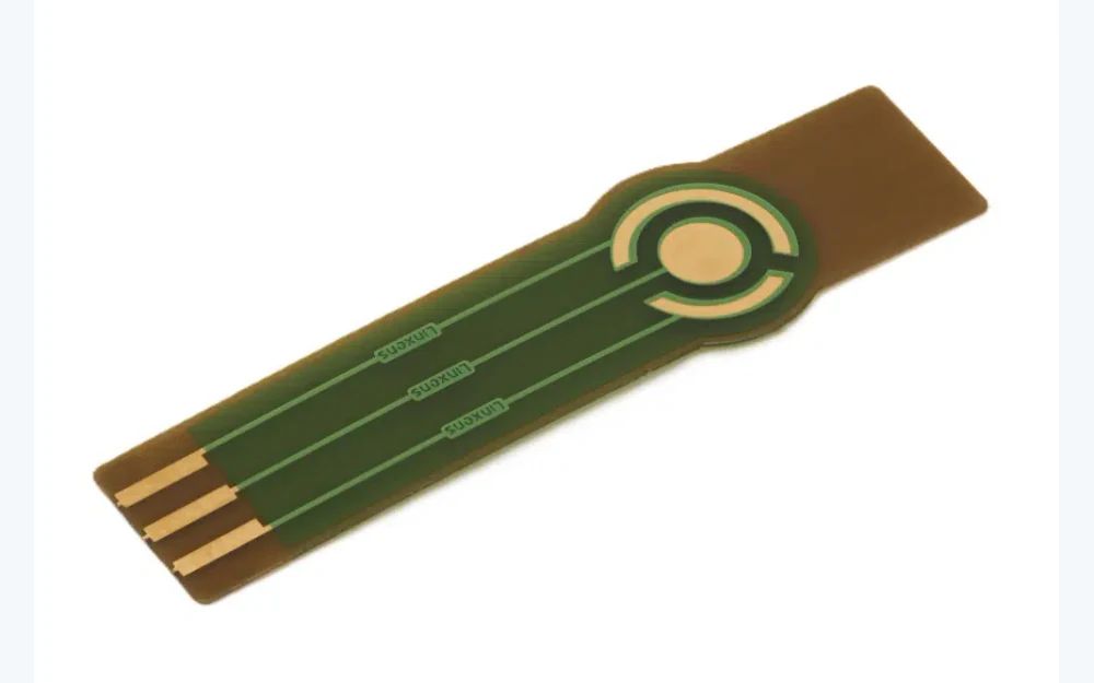
The useful manufacturing input is more than an outside shape. It identifies every active site, conductive path, insulation opening, tail conductor, connector land, reference feature, keep-out, bend zone, registration mark, and electrical relationship needed for printing and converting.

  • provide vector artwork or controlled circuit geometry
  • identify active contact areas separately from covered traces
  • dimension channel spacing, tail exit, bend keep-outs, and connector lands
  • name resistance, continuity, isolation, and visual checks without assuming clinical performance
Exploded printed medical electrode patch layer stack
LAYER STACK

Treat Adhesive, Hydrogel, Backing, Liner, and Circuit as One Registered Stack

A material can be acceptable in isolation and still fail inside the planned construction. Thickness, overlap, edge exposure, die-cut tolerance, lamination pressure, release liner, trace protection, storage, and packaging all change the assembly delivered to the OEM.

  • release supplier and grade where the material is already selected
  • map skin-contact, non-contact, conductive, insulating, and handling zones
  • define overlap and edge conditions around every printed feature
  • assign biocompatibility, wear, shelf-life, sterilization, and packaging validation to named owners
Printed electrode patches arranged for converting inspection and packaging
CONVERTING AND EVIDENCE

Inspect Registration and Packaging Without Turning It into a Device Claim

Production evidence can confirm print appearance, dimensions, site position, continuity, resistance to an agreed method, isolation, connector attachment, lamination, die-cut registration, labels, count, and packaging state. It does not prove diagnostic accuracy, treatment outcome, patient safety, or finished-device compliance.

  • define first-article and lot-level inspection separately
  • retain artwork, material, process, fixture, and packaging revisions
  • protect contact surfaces, liners, tails, connectors, and labels after inspection
  • state which changes require new samples or OEM requalification

Develop the Printed Electrode from Use Boundary to Repeat Production

01

Define the OEM use boundary

Describe placement, signal or stimulation architecture, duration, environment, mating device, packaging, and every validation retained by the OEM.

02

Release circuit geometry

Provide electrode sites, conductive traces, dielectric openings, reference points, tail, connector lands, bend zones, and electrical acceptance.

03

Close the material stack

Name substrate, ink, backing, adhesive or hydrogel, foam or nonwoven, reinforcement, liner, labels, and approved alternatives.

04

Approve converted samples

Review print, registration, dimensions, electrical checks, attachment, lamination, die cut, peel behavior, handling, and package state.

05

Control repeat builds

Lock revisions, sources, process windows, fixtures, records, packaging, substitutions, notification, and OEM requalification triggers.

Where Printed Electrode Manufacturing Fits

The common capability is registered printed circuitry and converted flexible layers. The OEM application determines the remaining electrical, clinical, safety, and regulatory work.

01

Patient monitoring hardware

Custom patch formats and interfaces for OEM acquisition systems with released geometry and inspection.

02

Neurophysiology equipment

Multi-site flexible arrays and channel routing supplied to an OEM placement and signal-validation plan.

03

Muscle sensing systems

Paired and multi-site layouts with controlled spacing, flexible interconnect, and connector handoff.

04

Stimulation-device programs

Custom conductive pad constructions manufactured to OEM-released electrical and use boundaries.

05

Wearable sensing platforms

Printed sensing sites, flexible circuits, tails, component lands, backing, adhesive zones, and packaged handoff.

06

Research and custom instruments

Application-specific printed arrays for projects whose geometry does not match a standard electrode format.

RFQ PACKAGE

Send the Circuit, Layer Stack, Interface, and Validation Boundary

Early concepts are useful when they show the intended electrode map and customer handoff. Missing material or inspection decisions can then be closed before tooling and repeat conversion.

  • electrode-site geometry, conductive traces, dielectric openings, channel identity, reference locations, and registration datums
  • substrate, conductive ink, backing, adhesive or hydrogel, foam or nonwoven, reinforcement, liner, labels, and approved sources
  • tail exit, conductor pitch, bend zones, connector or snap, lead attachment, mating interface, strain relief, and handling limits
  • outside profile, openings, adhesive-free zones, edge exposure, die-cut tolerances, laminate overlap, and assembly orientation
  • continuity, resistance, isolation, dimensional, visual, attachment, registration, cleanliness, and packaging acceptance methods
  • prototype quantity, annual estimate, lot definition, traceability, storage and shipment conditions, change control, and OEM validation plan
Send Electrode Project Files

Medical Electrode Pad Manufacturing FAQ

What types of medical electrode products can JASPER manufacture?

JASPER can review electrode products whose functional circuit can be produced with printed conductive geometry, including custom patches, flexible multi-site arrays, wearable circuits, tails, connectors, and project-specified converted layers.

Can adhesive or hydrogel layers be included?

They can be included when the project releases the exact material, supplier or approved alternative, zone geometry, thickness, overlap, liner, handling, storage, packaging, inspection, and customer validation responsibilities.

Does JASPER validate clinical or treatment performance?

No. JASPER can perform agreed manufacturing and electrical inspections on the supplied construction. Diagnostic accuracy, treatment outcome, placement, wear, biocompatibility, patient safety, finished-device performance, and regulatory approval remain with the OEM.

Can JASPER produce a custom electrode array from our circuit artwork?

Yes, when the artwork identifies active sites, printed traces, dielectric openings, tail and connector geometry, materials, dimensions, tolerances, electrical tests, converting stack, and customer handoff.

What should be approved before production?

Approve the print master, material sources, layer stack, registration, die cut, interconnect, electrical acceptance method, visual criteria, labels, packaging, traceability, and changes that require new samples or OEM requalification.

Related Printed Interface Products

Put the electrode map, layer stack, connector, and OEM validation boundary in one review.

JASPER can review printed conductive geometry, flexible substrates, converted layers, die cutting, interconnect, inspection, packaging, traceability, and change control for a custom electrode product.

Start Electrode Design ReviewContact Engineering