Dongguan, Guangdong 523927, China[email protected]+86 136 3262 5290
Home / Products / Custom Silicone Rubber Keypads for OEM Controls
MOLDED OEM KEYPAD MANUFACTURING

Custom Silicone Rubber Keypads for OEM Controls

A custom silicone rubber keypad is a molded input surface whose key geometry, return behavior, conductive contact, legends, lighting, PCB landing, enclosure support, and production evidence must work as one installed control.

Original three-dimensional group of conductive, backlit, and assembled silicone rubber keypads
4 product routesconductive, backlit, laser-etched, and assembled keypads
One mechanical systemkey cap, web, travel, return, stop, and enclosure support
One electrical pathcontact, PCB or FPC landing, connector, and test evidence

Silicone Rubber Keypad Products

Compare all four product routes by the engineering decision that still needs to be closed.

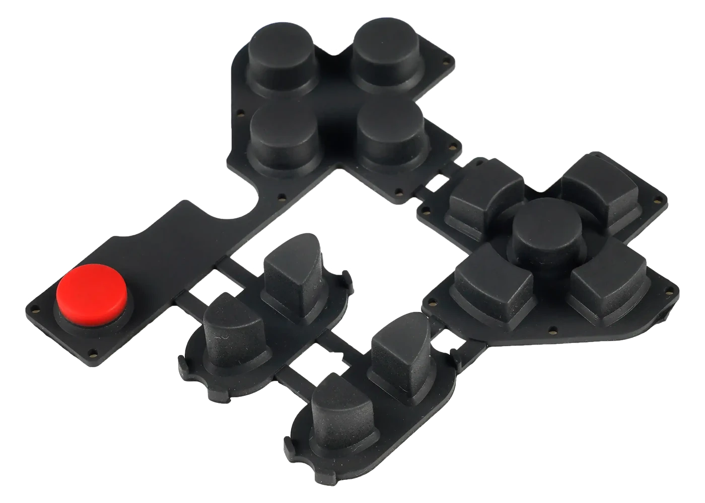
Conductive Rubber Keypads

Conductive Rubber Keypads

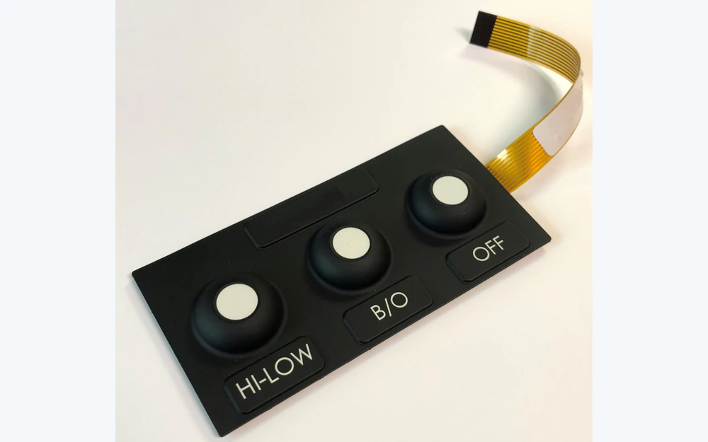
Molded keys with carbon pills or another released actuator and contact route for PCB, FPC, PET, or membrane circuits.

Choose it when: Start here when contact geometry, landing overlap, resistance evidence, force curve, and clean switching drive the project.

View Conductive Rubber Keypads
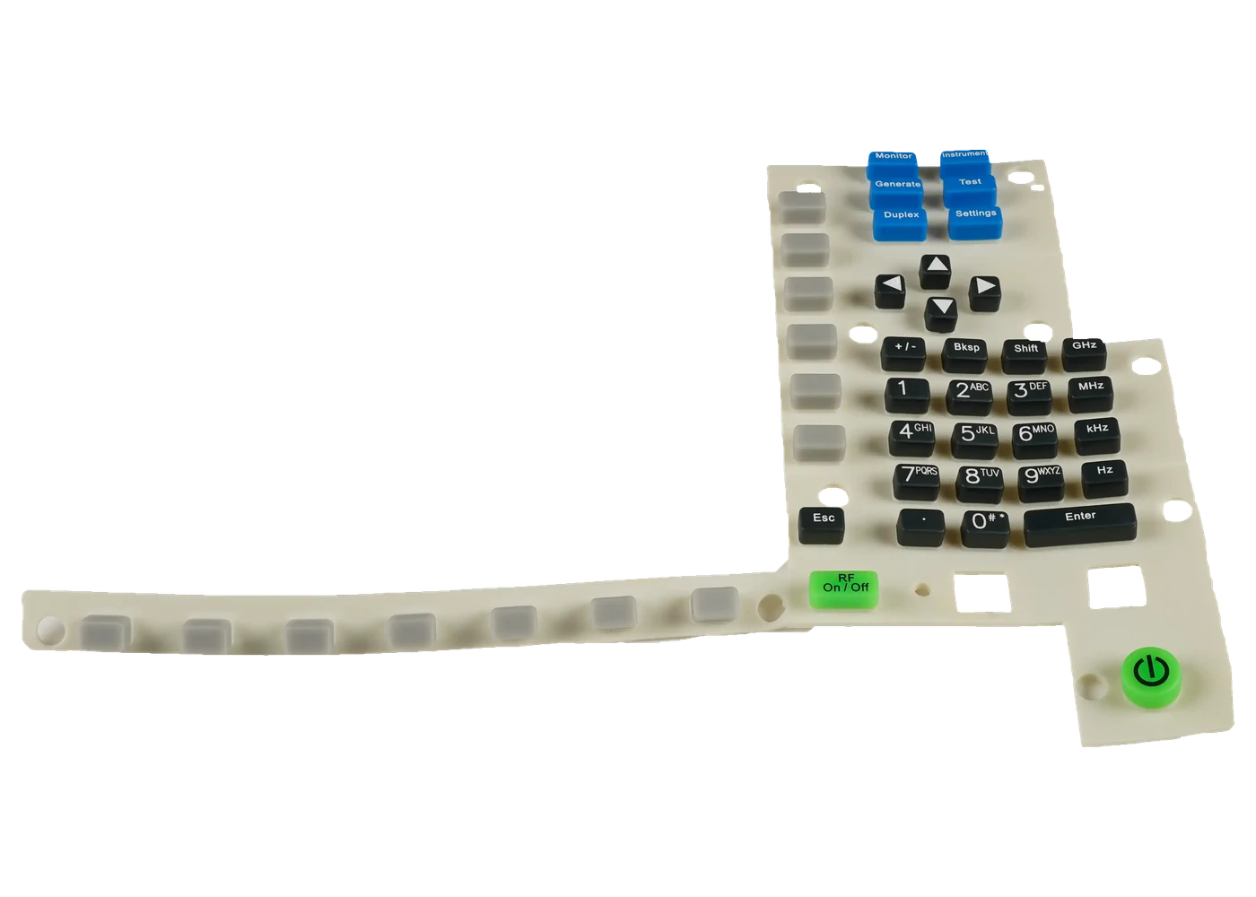
Backlit Silicone Rubber Keypads

Backlit Silicone Rubber Keypads

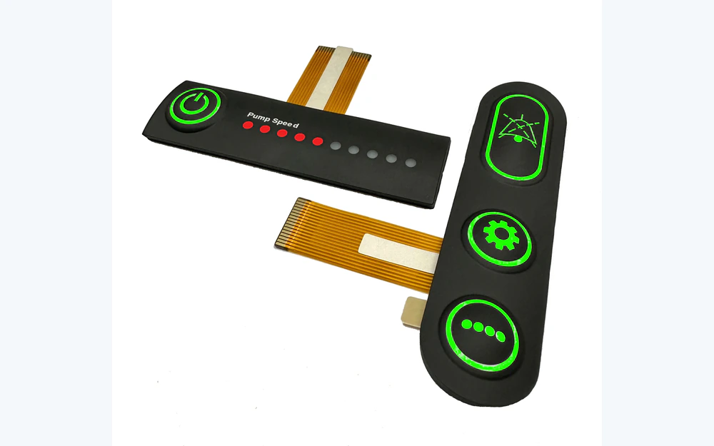
Translucent or selected base silicone, opaque color systems, LED paths, legend windows, diffusion, and light blocking.

Choose it when: Start here when the powered and unpowered appearance must be approved with the real LED, PCB, housing, and viewing condition.

View Backlit Silicone Rubber Keypads
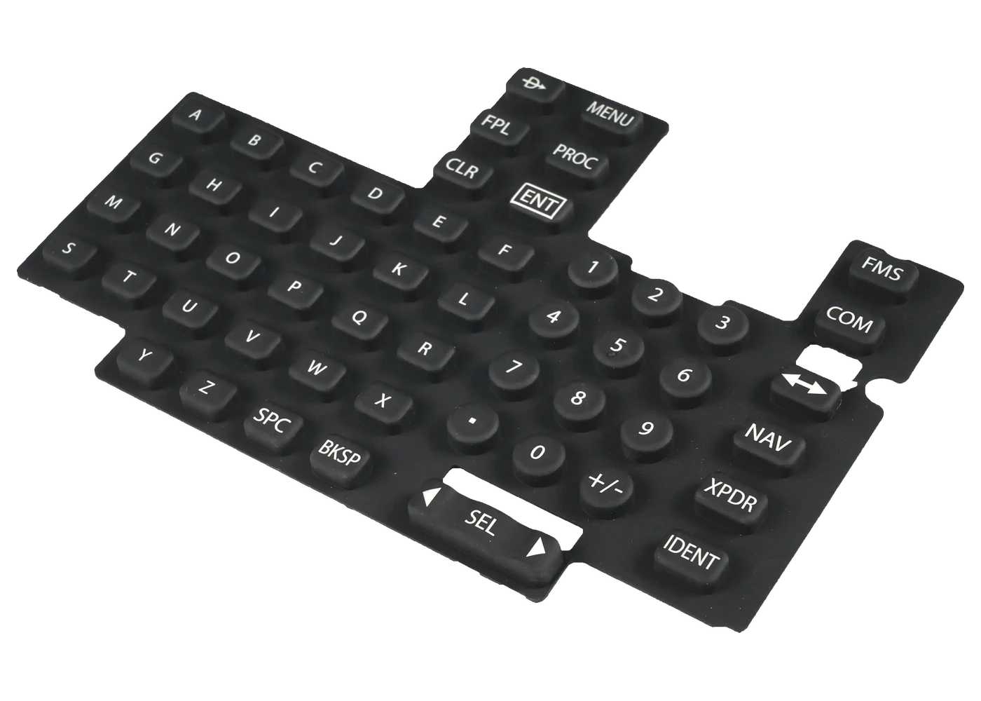
Laser-Etched Silicone Keypads

Laser-Etched Silicone Keypads

Coated molded keys with controlled laser-opened legends for contrast, illuminated symbols, and project-defined wear zones.

Choose it when: Start here when artwork, coating, laser opening, backlight transmission, and legend retention must be released together.

View Laser-Etched Silicone Keypads
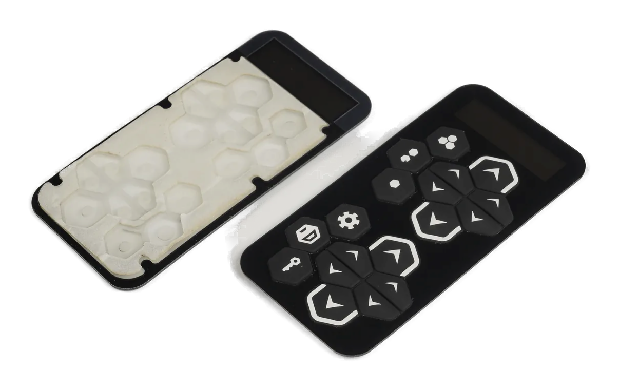
Silicone Keypad Assemblies

Silicone Keypad Assemblies

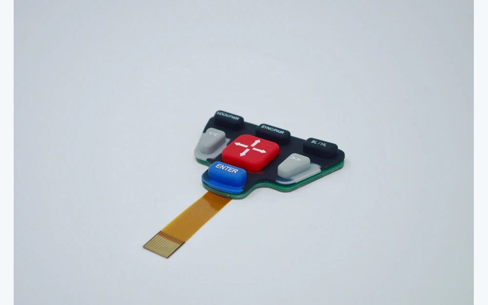
Keypad, PCB or FPC, LEDs, connector, spacer, carrier, enclosure interface, and functional inspection in one supplied module.

Choose it when: Start here when purchasing needs one accountable installed stack instead of separate rubber, circuit, lighting, and assembly suppliers.

View Silicone Keypad Assemblies

The Molded Key Is Only One Part of the Working Keypad

A silicone rubber keypad uses molded elastomer geometry to locate the operator's finger, move through a defined path, actuate a contact or switch, and return after release. Its visible key top does not prove how the contact lands, how the key bottoms, or how the housing supports the web.

The production release should connect the keypad drawing to the PCB or circuit, enclosure model, legend artwork, lighting plan, spacer and adhesive stack, first article, and test method. That is the difference between buying a rubber mat and buying a controlled OEM interface.

Use a membrane keypad when the front must remain thin and flat. Use silicone when raised geometry, molded travel, finger location, an elastomer sealing feature, or integration with a PCB and housing better fits the product.

Custom silicone rubber keypads fit when:

  • raised or sculpted keys help operators locate controls by touch
  • the design needs molded travel and return behavior rather than a flat overlay
  • conductive contacts, legends, lighting, circuit, and housing can be reviewed together
  • the OEM can approve the installed sample instead of only a loose molded keypad

Choose the Route by the Unresolved Engineering Risk

The four routes can overlap. Choose the page that owns the hardest open decision, then confirm whether the supplied scope should stop at the molded keypad or continue through a tested assembly.

Product RoutePrimary Buyer QuestionEvidence to Approve
Conductive rubber keypadWill every key close the intended circuit after tolerance, contamination, and installed compression are included?Keypad and circuit drawing, contact overlap, force curve, resistance method, and actuated sample
Backlit silicone keypadWill the powered and unpowered control remain readable without hot spots, edge glow, or cross-lighting?Artwork, color sample, LED and PCB layout, optical sample, viewing condition, and enclosure
Laser-etched silicone keypadWill the opened legend have the approved shape, contrast, transmission, surface, and wear behavior?Vector artwork, coating stack, laser sample, lighting condition, wear zone, cleaner, and retained master
Silicone keypad assemblyWho owns alignment, stack height, connector, lighting, sealing interface, and final function?Assembly drawing, bill of materials, test plan, installed first article, packaging, and change control
Three-dimensional silicone key section showing the key cap, web geometry, and hard stop
KEY FEEL IS GEOMETRY

Force, Travel, Return, and Web Geometry Must Be Tuned Together

A force target without the key size, web profile, travel path, support, stop, material, temperature, and measurement method is incomplete. The enclosure can change the result even when the loose keypad matches its drawing.

  • define the measurement point, speed, installed support, and conditioning state
  • review neighboring keys and housing ribs that may restrain the web
  • separate contact closure from hard-stop or housing-bottoming behavior
  • approve return and key-to-key consistency in the intended assembly
Exploded three-dimensional silicone keypad with carbon contacts and PCB landing areas
CONTACT AND CIRCUIT

The Contact Must Land on the Circuit After the Tolerance Stack Moves

Carbon pills, conductive coatings, metal domes, or non-conductive actuators solve different electrical and tactile problems. The selected contact route needs enough landing area and a defined path to the circuit after molding, board, spacer, and enclosure tolerances are included.

  • release contact type, geometry, location, orientation, and substitution rule
  • review PCB or circuit pad pattern, finish, contamination, and cleaning controls
  • define closure, overtravel, resistance, continuity, and test fixture behavior
  • inspect the installed datum path rather than centering parts by eye
Three-dimensional illuminated silicone keys above controlled LED and light-blocking positions
COLOR, LEGENDS, AND LIGHT

Artwork, Coating, Laser Openings, and LEDs Form One Optical System

A key can look correct in daylight and fail when illuminated, or look clean in a dark room and lose contrast when unpowered. The surface color, coating opacity, legend method, line width, LED location, diffusion, light block, cleaner, and wear zone should be sampled together.

  • approve powered and unpowered appearance under named viewing conditions
  • control legend artwork, scale, registration, color, and revision
  • use barriers, ribs, spacer color, and housing geometry to manage light leakage
  • qualify the complete print, laser, coating, and cleaning stack
Exploded three-dimensional silicone keypad, PCB or FPC, connector, and carrier assembly
INSTALLED STACK

PCB, FPC, Enclosure, Hard Stops, and Sealing Decide the Final Result

A loose keypad may pass appearance and basic feel checks while the installed product binds a key, shifts a contact, creates a light leak, or changes compression. The controlled product is the keypad inside its real circuit and enclosure boundary.

  • share the enclosure and circuit model before mold geometry is frozen
  • define locating features, support, compression, stops, connector path, and service
  • treat sealing as an assembly result with a named exposure and test
  • approve fit, key feel, contact, lighting, and removal on the installed first article

Release the Tool, Artwork, Circuit, and Installed Sample Together

01

Define the operator and duty

Record key use, gloves, environment, cleaning, lighting, expected interfaces, and non-negotiable requirements.

02

Close the mechanical stack

Align key geometry, web, travel path, return, hard stop, housing support, circuit height, and tolerance datums.

03

Close contact and graphics

Release contact route, PCB landing, artwork, color, coating, legend, lighting, connector, and test points.

04

Approve the installed first article

Inspect the keypad in the real enclosure for appearance, key feel, contact, light, fit, compression, and service access.

05

Control production changes

Lock approved materials, tool revision, artwork, circuit, process, inspection, packaging, and requalification triggers.

Where Custom Silicone Rubber Keypads Fit

The common requirement is a molded operator interface whose mechanical, electrical, optical, and installed boundaries can be approved together.

01

Industrial controls

Raised keys for machine panels, handheld controls, test equipment, and field instruments.

02

Medical and laboratory equipment

Molded controls reviewed around cleaning, glove use, legends, circuit, enclosure, and evidence.

03

Transportation interfaces

Seat, console, service, remote, and specialty vehicle controls with project-defined environment and lighting.

04

Marine and outdoor controls

Keypads whose molded edge, enclosure, connector, and exposure are reviewed as an installed system.

05

Appliances and equipment

Tactile molded controls with color, symbols, lighting, and circuit integration for repeated use.

06

Security and access products

PIN pads, remotes, alarms, and controllers where key location, wear, moisture, and visibility matter.

Send the Keypad, Circuit, and Enclosure Information Together

Early files do not need to be complete. A layout, enclosure model, circuit image, legend artwork, and note about the use environment are enough to begin a useful engineering review.

  • keypad outline, 2D drawing, 3D model, sample photo, or installed concept
  • key count, cap geometry, pitch, travel direction, feel target, and hard-stop concept
  • contact method, PCB or FPC landing, pinout, connector, and electrical test requirement
  • artwork, colors, legend method, powered and unpowered appearance, and lighting plan
  • enclosure material, support, locating features, compression, sealing, and service route
  • environment, cleaner, gloves, wear zones, sample quantity, annual volume, and approval evidence
Send Silicone Keypad Project Files

Silicone Rubber Keypad FAQ

What is a silicone rubber keypad?

It is a molded elastomer input part whose key cap and web move an actuator or conductive contact toward a PCB, FPC, PET, membrane, or other switch interface. The working product also depends on the circuit, enclosure support, legends, lighting, and installed stack.

How do we choose a silicone rubber keypad manufacturer?

Compare how the supplier reviews key geometry, contact and PCB landing, artwork, coating, lighting, tooling, installed first articles, test evidence, revision control, and responsibility for adjacent parts. A molding quote alone does not close those interfaces.

Can a custom silicone rubber keypad include a PCB and LEDs?

Yes, when the project scope defines the keypad, circuit, LEDs, connector, spacer, carrier, enclosure interface, functional test, packaging, and change control. The Silicone Keypad Assemblies page owns that integrated route.

What values should be included on the drawing?

Include the finished geometry, datums, contact location, circuit relationship, target key behavior, artwork, color, coating, lighting, environment, inspection, and installed condition. Use project-specific values and test methods instead of generic catalog assumptions.

Should we choose a silicone keypad or a membrane keypad?

Choose silicone when raised geometry, molded travel, finger location, an elastomer edge, or integration with a PCB and housing drive the product. Choose a membrane keypad when a thin flat surface, printed front graphics, and a low-profile sealed stack matter more.

Silicone Keypad Design Resources

Review the keypad in the real circuit and enclosure before tooling release.

JASPER can review the molded geometry, contact, artwork, lighting, PCB or FPC, enclosure, sample evidence, and production controls as one custom silicone keypad project.

Start Silicone Keypad ReviewContact Engineering