
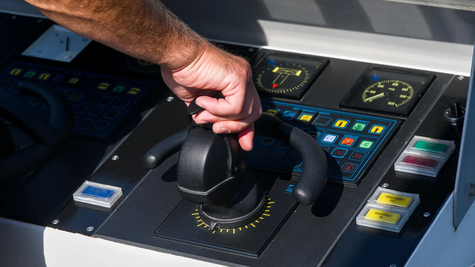
Audit every route that water can take
A marine membrane switch or pool equipment control panel is not protected by one front-film choice. Spray, runoff, standing water, condensation, cutouts, tail exits, rear connectors, and service work reach different boundaries. Put all six paths on the installed drawing before materials, adhesive, gasket geometry, and test conditions are released.
- 01
Face and key field
Rain, splash, wet fingers, wash water, and a water film reach legends, key edges, display windows, and indicator openings first.
Define the exposed face, key construction, window stack, surface finish, cleaning method, wet-operation behavior, and visual acceptance after exposure.
- 02
Upper edge and runoff
Water running down a console, helm, spa wall, or equipment housing concentrates at the upper edge and any horizontal ledge.
Show orientation, overhang, drainage direction, edge radius, adhesive or gasket land, joint location, and where water is allowed to leave.
- 03
Perimeter and cutouts
Housing flatness, fastener load, window openings, speaker holes, displays, and decorative seams can interrupt an otherwise continuous front boundary.
Control datums, flatness, land width, corner geometry, compression, hard stops, cutout sealing, and the production assembly sequence.
- 04
Tail or cable exit
A flexible tail can create a capillary path, a local thickness step, a sharp bend, or an opening that bypasses the front seal.
Release exit position, filler or gasket detail, bend zone, strain relief, slot edge, cable route, dry-zone boundary, and service motion.
- 05
Rear enclosure and vent
Condensation, hose direction, deck runoff, plumbing leaks, open service doors, and pressure equalization can wet the rear even when the face remains intact.
Map vents, drains, enclosure joints, mounting studs, rear cover, internal drip paths, electronics clearance, and powered recovery criteria.
- 06
Connector and reassembly
Salt residue, sanitizer mist, damp harnesses, uncapped connectors, and displaced seals often appear after installation or maintenance.
Specify connector location, cap or boot, mating state, cable gland, inspection, seal renewal, torque or closure method, and return-to-service test.
Marine and pool controls share water, not the same duty cycle
Both product groups operate near water and sunlight, but their contaminants, operator tasks, installation geometry, and service routines differ. Start with the equipment lane, then define the exact mounting location instead of carrying a generic outdoor keypad specification across every model.
Boat and vessel controls combine direct spray, salt-laden moisture, glare, vibration, night operation, oils, cleaners, cable movement, and limited service access. The interface must make the correct action clear while the vessel, operator, and light are moving.
- 01
Helm, bridge, and navigation support
Chartplotter surrounds, switch panels, lighting controls, trim or auxiliary controls, and status panels need visible grouping, stable tactile references where required, controlled display windows, night dimming, and installation datums shared with the console.
- 02
Deck, cockpit, and exterior stations
Open-deck controls, winch or lift interfaces, bait-well and pump panels, and secondary steering stations receive spray, runoff, gloves, sunscreen, salt residue, and impact from routine work around the station.
- 03
Engine-room and equipment controls
Pump, generator, ventilation, tank, alarm, and service panels may see heat, oil film, cleaning chemicals, vibration, damp cables, and infrequent but high-consequence operation by a trained user.
Pool equipment controls combine outdoor weather with sanitizer splash, wet hands, sunscreen, water-treatment chemicals, equipment-pad cleaning, plumbing leaks, and seasonal service. The front must separate everyday operation from setup and service states.
- 01
Pool and spa automation
Wall, equipment-pad, and remote panels coordinate pumps, heaters, lighting, valves, schedules, water features, and service modes. Fixed actions, changing settings, status, faults, and lockouts need a deliberate hierarchy.
- 02
Spa-side and wet-user controls
Users may reach a small keypad with wet hands while seated, in bright daylight, or at night. Large targets, positive feedback, restrained function count, legend contrast, and water-film behavior matter more than menu density.
- 03
Pumps, filtration, and water treatment
Pump controllers, dosing equipment, filtration systems, chlorination or treatment skids, and plant-room panels need clear operating states, chemical exposure mapping, cable protection, ventilation, drainage, and technician access.
Choose the input architecture from the operator and exposure
The same enclosure can use a membrane keypad, silicone rubber keys, a capacitive panel, a touchscreen, or a hybrid HMI. Decide from fixed versus changing functions, tactile confirmation, gloves, water films, optical needs, electronics, mounting depth, and service responsibility before artwork makes the choice appear final.
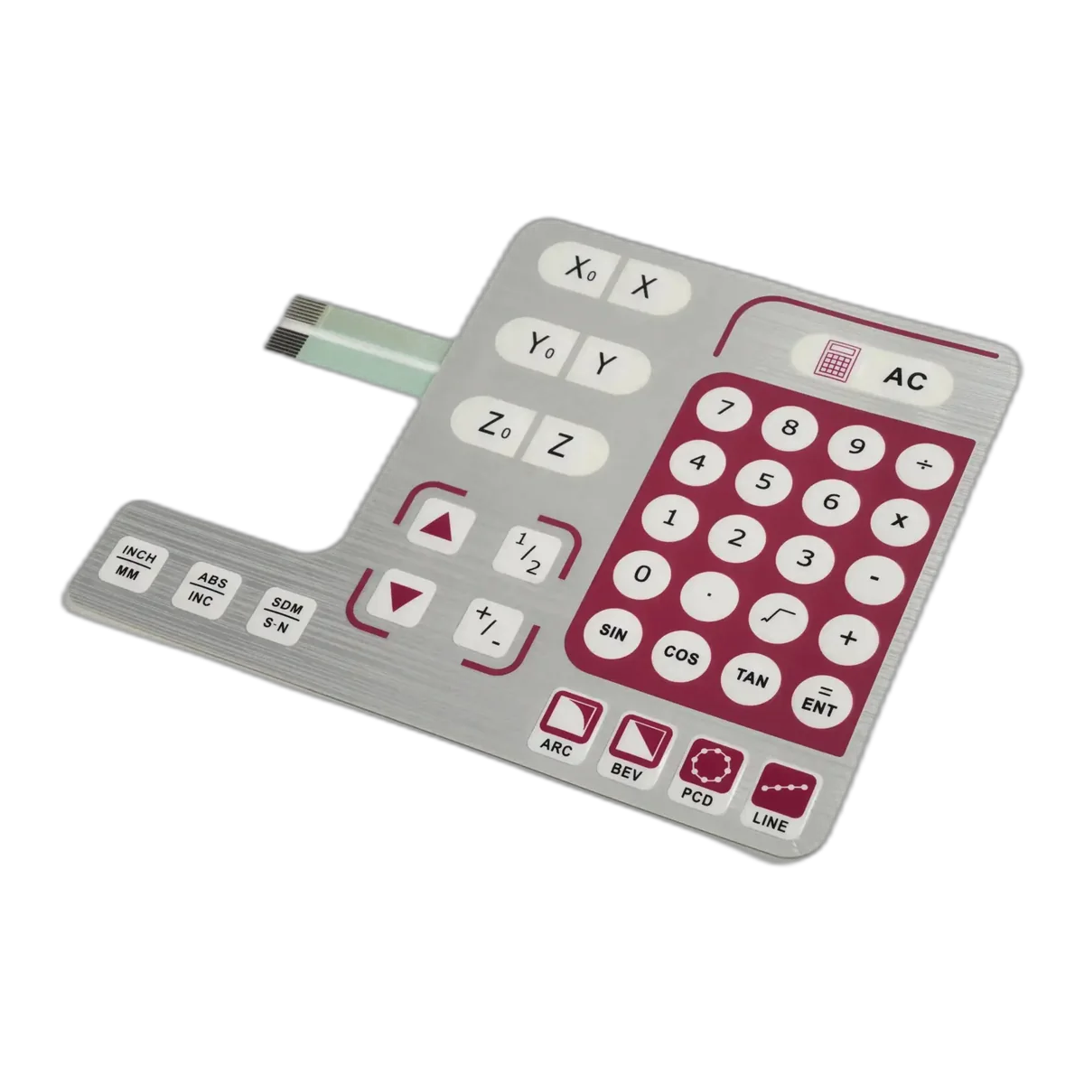
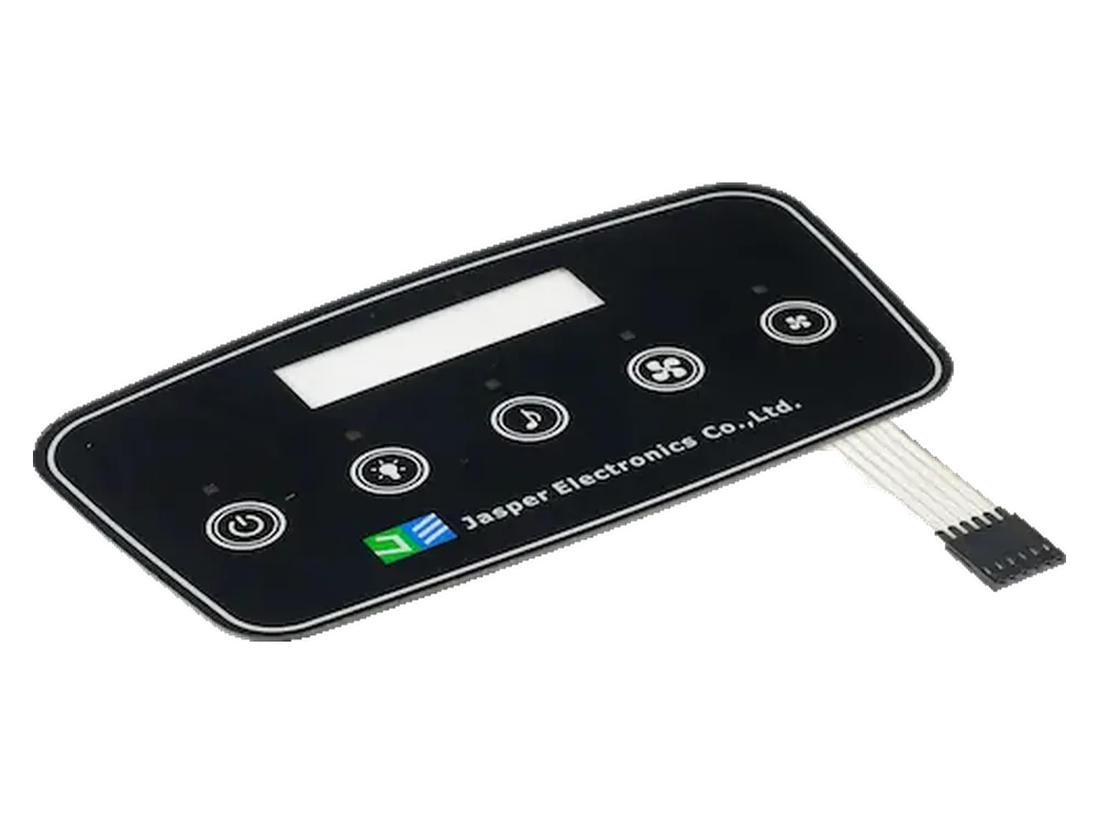
Sealed membrane switch
A practical route for fixed commands, printed status legends, tactile or non-tactile keys, LEDs, a low-profile stack, and a continuous cleanable face.
Define dome or flat contacts, support, actuation target, perimeter, windows, adhesive, tail exit, connector, controller response, and installed exposure.
Silicone rubber keypad
Raised keys improve finger location and can support glove use, strong travel cues, molded light guides, and a housing-integrated keymat.
Define web and key geometry, bezel clearance, compression, PCB contact system, flange or sealing feature, material exposure, drainage, and replacement method.
Capacitive or touchscreen front
A flush surface supports changing menus, smooth graphics, display integration, and reduced mechanical openings when the use case accepts electronic feedback.
Tune cover thickness, sensor, ground, controller, water-film rejection, gloves, edge behavior, EMC environment, display, firmware, and mounted calibration together.
Hybrid marine HMI assembly
A display or touchscreen can handle settings while fixed tactile controls provide direct access to frequently used or confirmation-critical functions.
Release the overlay or cover, display, physical controls, sensor, circuit, carrier, gasket, cables, connectors, indicators, firmware interface, and functional-test boundary as one package.
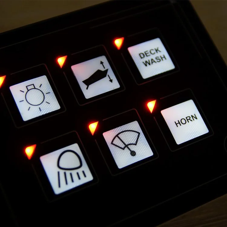
Approve wet use, sunlight, and night states separately
Environmental survival does not prove usable control. A sealed panel can still misread a water film, hide a legend in glare, bloom around an indicator at night, or give no confirmation through a glove. Review each operating state on the powered assembly at its installed angle.
- 01
Wet hands and surface water
Define whether input must work during droplets, a continuous film, runoff, or only after wiping. Check false activation, missed input, repeated input, water bridging, palm contact, and the recovery state.
- 02
Gloves and moving operation
Name glove type and thickness, hand position, available force, vibration or vessel motion, and whether the operator can locate the control without reading every legend.
- 03
Direct sun and reflected glare
Review contrast at the actual viewing angle with bright sky, water reflection, glossy surroundings, polarized eyewear where relevant, surface texture, window tint, display air gap, and fingerprints.
- 04
Night and low-light operation
Set backlight groups, dimming range, icon priority, leakage, hot spots, indicator meaning, dark adaptation, and the unpowered appearance. Avoid making every legend equally bright.
- 05
Display-window registration
Tie cover opening, printed mask, adhesive, sensor edge, display view area, active touch area, enclosure cutout, and software targets to controlled datums and the real stack height.
- 06
Feedback and fault states
Coordinate tactile feel, display response, LEDs, sound, lockout, timeout, communication loss, sensor fault, pump or heater status, alarms, and service mode so one action produces one understandable result.
Send the wet boundary, operator states, cable route, and open decisions for an engineering review.
Write an exposure ledger, not a broad chemical claim
Name what reaches the panel, where it lands, how long it remains, how it is removed, and what failure would be unacceptable. Marine and pool programs should not share a single unchecked chemical list.
Salt-laden moisture
Marine spray, damp air, dried salt, and repeated wet-dry cycles can leave conductive or corrosive residue at edges, metal hardware, tails, connectors, and damaged coatings.
Include residue accumulation, rinse or cleaning practice, metal interfaces, connector state, powered exposure, recovery, and inspection of hidden paths.
Fuel, oil, and workshop fluids
Fuel splash, lubricants, hydraulic fluid, bilge residue, hand cleaners, sealants, and maintenance chemicals may reach selected vessel stations.
Use the exact project fluids, concentration, contact method, dwell, wipe material, temperature, repetitions, and cosmetic plus functional acceptance.
Sanitizers and water treatment
Chlorine- or bromine-related products, saltwater-pool residue, pH chemicals, dosing splash, and concentrated service chemicals differ from balanced pool water.
Separate normal wet-user contact from equipment-pad or treatment-room service exposure and test only the concentrations and methods defined by the OEM.
Sunscreen, skin oils, and cosmetics
Wet users repeatedly transfer sunscreen, lotions, skin oil, and cleaning residue to spa-side, deck, and handheld controls.
Evaluate high-touch legends, clear windows, matte or gloss zones, edges, embossing, key feel, cleaning, staining, softening, and loss of adhesion.
Cleaning and disinfection
Freshwater rinse, detergent, disinfectant, pressure spray, brush, cloth, and equipment-pad cleaner create different abrasion and ingress mechanisms.
Specify product, dilution, application, dwell, temperature, tool, direction, frequency, rinse, drying, and acceptance instead of writing cleanable alone.
Temperature, UV, and condensation
Sun-heated dark panels, cool nights, equipment heat, seasonal storage, humidity, and rapid temperature changes affect print, film, adhesive, seals, windows, and internal moisture.
Define orientation, shade, powered heat, storage, UV method, temperature transitions, condensation state, dimensional movement, optical checks, and post-exposure operation.
Close the boundary from the printed face to the rear connector
The useful section view includes the overlay, switch or sensor, adhesive or gasket, enclosure land, opening, tail or cable, rear hardware, and intended dry zone. Review the stack as an installed cross-section, not as isolated purchased parts.
- 01
Printed face
Select film, coating, ink, texture, transparent windows, embossing, and legends from the named optical, touch, abrasion, UV, and chemical conditions.
- 02
Switch or sensor stack
Control layer registration, spacer channels, dome support, venting if used, circuit insulation, sensor border, LED or window openings, and edge termination.
- 03
Perimeter bond or gasket
Keep a continuous land around keys, windows, cutouts, and the outer edge. Define substrate material, finish, flatness, cleanliness, pressure, cure, compression, and hard stops.
- 04
Housing and openings
Place fasteners, bosses, display cutouts, speaker or vent openings, joints, ribs, and edge radii so they support rather than interrupt the intended wet boundary.
- 05
Tail, cable, and strain relief
Show contact side, stiffener, bend radius, slot geometry, local filler or boot, sharp-edge protection, slack, clamp, hinge motion, and the transition into the protected area.
- 06
Rear connector and dry zone
Define the mated connector, cap for unused ports, cable gland, PCB clearance, drip loop, drainage, vent position, rear cover, service access, and evidence that marks the allowed dry region.
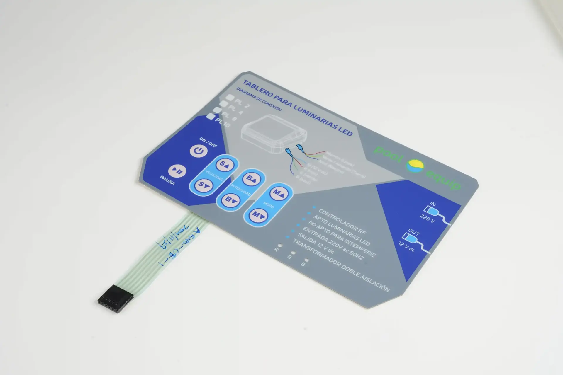
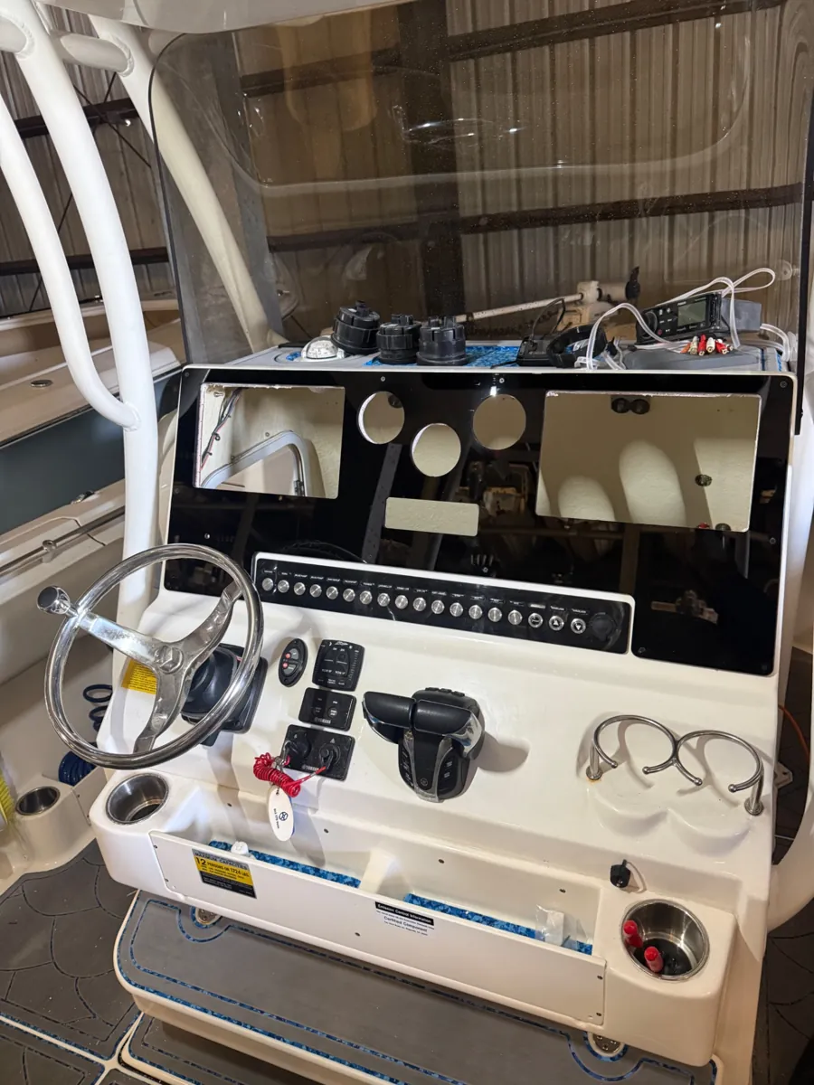
Design installation and service into the first release
Many field leaks and intermittent controls begin after the interface leaves the component drawing. Mounting angle, drainage, cable routing, ventilation, fastener sequence, and reassembly determine whether the released boundary survives real installation.
- 01
Set mounting datums
Reference panel outline, display, active keys, cutouts, adhesive or gasket land, fasteners, housing surface, and internal carrier from the same controlled datum scheme.
- 02
Give water an exit
Use orientation, slope, overhang, drip edges, drainage gaps, and protected openings to prevent standing water from concentrating at the upper edge, tail slot, connector, or service seam.
- 03
Route air deliberately
If the equipment needs ventilation or pressure equalization, place the vent and internal path so it does not defeat the front boundary or direct condensate toward electronics.
- 04
Protect the harness
Control bend radius, slack, strain relief, clamps, abrasion points, hinge sweep, heat sources, plumbing, mating access, labeling, and connector retention through installation and service.
- 05
Release reassembly
Document surface preparation, adhesive or gasket replacement, compression or closure sequence, cable checks, connector caps, visual inspection, powered self-test, and return-to-service evidence.
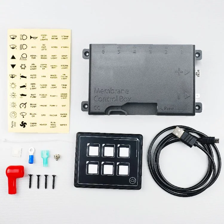
Set the supplied assembly boundary before quotation
A clear responsibility map prevents a component result from being read as evidence for the complete boat, pool controller, spa system, pump, heater, or treatment skid.
Custom interface component or agreed assembly
- custom graphic overlay, membrane switch, silicone keypad, capacitive panel, printed circuit, tail, connector, LED, backlighting, gasket, carrier, and agreed physical HMI assembly
- released materials, artwork, dimensions, datums, circuit, pinout, key map, cable details, cosmetic criteria, component inspection, and agreed functional checks
- design-for-manufacture review of the supplied interface boundary, production-intent samples, revision control, packaging, and project-defined records
Complete installed equipment and intended use
- intended use, operator tasks, alarms, control logic, pumps, heaters, valves, dosing, water chemistry, navigation or vessel functions, display, controller, software, communications, and cybersecurity
- housing, mounting surface, openings, fasteners, drainage, ventilation, cable entries, power, grounding, electrical safety, installation, service, and field environment
- complete-equipment ingress target, salt or chemical specification, risk assessment, regulatory route, certification, production release, installation instructions, and final validation
Qualify a mounted, powered, and serviceable assembly
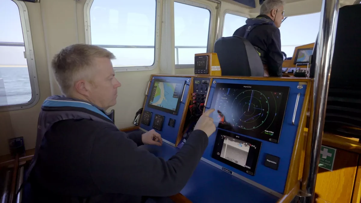
A loose membrane switch can confirm artwork, dimensions, key feel, and continuity. It cannot reproduce enclosure flatness, gasket load, display optics, grounding, tail strain, connector position, water direction, software response, drainage, or maintenance. Approval should use the production-intent installation and OEM-owned acceptance criteria.
- 01
Freeze the exposure map
Record installation, water sources, chemicals, UV, temperature, wet-hand and glove states, cleaning, service access, powered condition, repetitions, recovery, and pass criteria.
- 02
Build the intended stack
Use released face materials, circuit or sensor, display, adhesive or gasket, enclosure surface, openings, hardware, tail, cables, connectors, controller, indicators, and software state.
- 03
Exercise operation first
Confirm every key or touch target, tactile and visual feedback, glare and night states, alarms, lockouts, communication loss, service mode, and safe recovery before exposure.
- 04
Apply the named conditions
Expose the mounted article from representative directions and operating states. Inspect runoff, pooling, edges, windows, tail exit, rear enclosure, connectors, and internal evidence.
- 05
Recover, inspect, and release
Repeat operation after exposure and defined recovery, then record appearance, adhesion, optics, electrical state, moisture or residue, cable condition, service reassembly, revision, and disposition.

Production evidence tied to the wet-location drawing
JASPER manufactures the released interface component or agreed assembly and records the controls named by its drawing and control plan. Graphics, circuit, sealing features, tail, connector, options, and revision must stay connected to the same production identity.
- Identity
- Released artwork, language, material stack, dimensions, datums, circuit master, pinout, tail or cable, connector, sealing detail, variant, and revision.
- Appearance
- Print registration, legends, color reference, finish, transparent windows, masks, cut edges, embossing, illumination zones, and agreed cosmetic limits.
- Electrical
- Project-defined continuity, open and short, key map, contact, LED polarity or function, touch-panel interface, tail, connector, and assembly checks.
- Mechanical
- Outline, openings, laminate registration, adhesive or gasket condition, carrier fit, cable restraint, labels, packaging, and agreed installed-fixture evidence.
Connect the installed boundary to the right interface route
Product directions
Review perimeter, windows, tail exit, adhesive or gasket, enclosure integration, and project-defined exposure evidence.
Use raised molded controls when finger location, glove operation, travel feedback, housing integration, or backlighting favors silicone.
Coordinate a flush custom face with sensing, display window, grounding, water behavior, gloves, backlighting, and controller tuning.
Define a supplied module with overlay or cover, controls, display interface, circuit, carrier, gasket, cabling, connectors, and agreed test.
Engineering resources
Separate spray and temporary-immersion objectives and define the complete installed article used for evidence.
Compare films, inks, circuits, windows, adhesives, support layers, and finishes against named exposure mechanisms.
Coordinate tail exit, bend, stiffener, connector, strain relief, cable route, dry zone, installation, and service.
Package enclosure CAD, control map, artwork, electronics, environment, quantities, variants, and approval evidence.
Send the installed wet-location interface package
A useful quotation identifies the equipment lane, mounting boundary, operator states, exposure ledger, electronics interface, service route, and evidence required at sample approval. Early drawings are suitable when open decisions are marked.
Open Wet-Location RFQ- 01equipment type, intended use, operator tasks, fixed and changing functions, alarms, fault recovery, languages, wet-hand and glove requirements
- 02front panel, display, enclosure, mounting orientation, datums, openings, fasteners, surface material, finish, flatness, adhesive or gasket land, and internal clearance
- 03rain, spray, runoff, pooling, condensation, salt, sanitizer, cleaners, sunscreen, oil, UV, temperature, abrasion, and storage conditions
- 04membrane, silicone, capacitive, touchscreen, or hybrid direction; key feel, artwork, windows, indicators, backlighting, day and night states
- 05circuit or sensor, schematic or matrix, electrical limits, controller, grounding, shielding, LEDs, tail or cable, connector, gland, strain relief, and test interface
- 06drainage, ventilation, plumbing proximity, rear cover, dry-zone definition, installation sequence, service access, seal renewal, and return-to-service check
- 07prototype quantity, annual volume by variant, schedule, exposure protocol, acceptance criteria, inspection records, labels, packaging, and supplier responsibility map
Marine and Pool Equipment Membrane Switch FAQ
What makes a membrane switch suitable for marine equipment?
A marine membrane switch is specified around the installed station: spray and runoff paths, salt-laden moisture, sunlight and night viewing, wet hands or gloves, fuel or oil exposure where relevant, enclosure flatness, perimeter and window sealing, tail and connector protection, vibration, drainage, service access, and powered functional validation. Material names alone do not establish the finished result.
How should a pool or spa control panel be designed for wet use?
Define whether the panel must operate with droplets, a water film, wet fingers, or only after wiping. Map sanitizer and sunscreen contact, direct sun, night lighting, cleaning, mounting orientation, runoff, standing water, openings, adhesive or gasket land, tail exit, rear connector, feedback, fault states, and service reassembly. Validate the production-intent mounted and powered assembly.
Should marine and pool controls use membrane, silicone, or capacitive keys?
Use a membrane switch for low-profile fixed controls and printed legends, silicone for raised keys and stronger finger location, capacitive controls for a flush face and electronic interface, and a hybrid when changing display functions need fixed direct-action keys. Choose from operator tasks, gloves, water films, feedback, optics, electronics, depth, mounting, cleaning, and service responsibility.
How are the flexible tail and connector protected from water and salt?
Release the tail exit, slot, local filler, gasket or boot, contact side, stiffener, bend radius, sharp-edge protection, slack, strain relief, cable route, clamp, gland, connector mating state, cap for unused ports, drip path, and intended dry zone. Include the complete route in mounted exposure, recovery, inspection, and service testing.
Can JASPER certify the complete panel as waterproof or saltwater resistant?
JASPER can manufacture the released interface and support agreed component or installed-sample checks. The complete result depends on the OEM enclosure, mounting surface, openings, gasket or adhesive, hardware, drainage, vents, cable entries, connectors, assembly process, exposure method, powered state, acceptance criteria, installation, service procedure, and final equipment validation.
What is needed to quote a marine or pool equipment HMI?
Send the equipment and operator workflow, front and enclosure CAD, mounting orientation, display and control map, artwork, materials and finishes, circuit or sensor details, tail and connector route, wet-hand and glove needs, named water, salt, chemical, UV, temperature, cleaning and abrasion conditions, drainage and service plan, sample quantity, annual volume, schedule, acceptance evidence, and supplier responsibilities.