

Where outdoor membrane switches are actually used
Outdoor equipment does not share one default keypad. The operator, enclosure, water source, service method, and viewing conditions determine whether the interface should be a flat membrane switch, a raised silicone keypad, or a more integrated HMI assembly.
Construction and agricultural equipment
Machine service panels, compact operator controls, irrigation controllers, remote pendants, and auxiliary vehicle interfaces.
- Operating reality
- Rain, mud, dust, vibration, sunlight, temperature swings, work gloves, and field cleaning reach the same front panel.
- Design direction
- Use spaced tactile keys, abrasion-resistant legends, a controlled tail route, and a mounting boundary that stays closed when the enclosure flexes or vibrates.
- Approval check
- Operate representative keys with the intended gloves, then inspect the installed panel after the agreed water, dirt, cleaning, and temperature sequence.
Gate, parking, and access-control equipment
PIN pads, gate controllers, intercom panels, parking terminals, and exterior security equipment.
- Operating reality
- Public use adds fingernail wear, repeated cleaning, direct rain, condensation, sunlight, and installation pressure from wall or door hardware.
- Design direction
- Keep legends readable, separate key zones clearly, protect indicator windows, and prevent the cable or tail slot from bypassing the front seal.
- Approval check
- Check daytime readability, wet-hand operation, repeated key response, enclosure drainage, and the complete cable path after installation.
EV charging and outdoor energy controls
Charging posts, battery cabinets, solar or inverter service panels, power-management controls, and outdoor status interfaces.
- Operating reality
- The interface can face full sun, night use, rain, thermal cycling, dust, cleaning, and cable entry points close to the operator surface.
- Design direction
- Coordinate dead-front or backlit icons, UV exposure, window masking, grounding or shielding needs, and connector protection with the cabinet design.
- Approval check
- Review the off-state and illuminated appearance, then test the installed interface at the defined viewing angles and environmental conditions.
Outdoor instrumentation and water-treatment equipment
Pump controllers, dosing equipment, field meters, weather instruments, monitoring stations, and process-control enclosures.
- Operating reality
- Condensation, splash, chemical residue, narrow display windows, frequent service access, and long cable routes create several paths around a sealed face.
- Design direction
- Define compatible overlay and adhesive materials, protect display openings, control venting and drainage, and keep the connector inside the intended dry zone.
- Approval check
- Inspect window clarity, graphics, key operation, electrical function, edge wicking, and internal evidence after the project exposure sequence.
Pool, spa, and outdoor recreation equipment
Pump and heater controls, spa panels, filtration interfaces, outdoor exercise equipment, and wet-hand user controls.
- Operating reality
- Wet hands, standing droplets, chlorinated cleaners, sunscreen, UV, heat, and repeated wipe-down can attack the face and its mounting boundary differently.
- Design direction
- Select the surface and graphics around known chemicals, keep water from pooling at edges, and define whether raised keys or a flat wipe-clean panel suits the user.
- Approval check
- Use the named chemicals and cleaning frequency on an installed sample, then check appearance, adhesion, key response, and internal moisture evidence.
Marine and specialty-vehicle accessories
Marine dashboards, deck controls, accessory panels, utility vehicles, and exposed mobile equipment interfaces.
- Operating reality
- Spray, salt residue, condensation, vibration, direct sun, night operation, curved housings, and cable service all affect the front module.
- Design direction
- Coordinate overlay, gasket or adhesive, housing geometry, daylight-visible indicators, tail strain relief, connector or gland, and a drainage route.
- Approval check
- Test the production-intent assembly in its mounting orientation and inspect every opening, edge, cable transition, and illuminated feature.
Define the outdoor exposure before naming an IP target
IP65 and IP67 are separate project targets, not interchangeable labels. The useful specification states where water comes from, how long it acts, which joints are exposed, whether the unit is powered, and what evidence is acceptable after the test.
| Exposure | Define before quote | Design focus | Sample evidence |
|---|---|---|---|
| Rain and splash | Direction, duration, mounting angle, runoff, pooling, wind, and powered state. | Perimeter continuity, corners, windows, upper edges, tail slot, and drainage. | Installed sample remains functional and shows no unacceptable ingress at the released boundaries. |
| Hose, jet, or washdown | Nozzle or equipment method, distance, direction, pressure class, temperature, chemistry, frequency, and access to seams. | Edge land, cutouts, enclosure joints, connector entry, gasket compression, and service covers. | Complete front module and enclosure are exposed and inspected to the buyer-defined procedure. |
| Pooling or temporary immersion | Water depth, time, orientation, trapped air, preconditioning, recovery time, and internal inspection method. | Continuous seal path, capillary routes, housing breathing, vent ownership, cable entry, and pressure change. | The production-intent assembly meets the project acceptance criteria after recovery and inspection. |
| UV and temperature cycling | Sun orientation, ambient range, enclosed solar heating, cycle profile, condensation risk, and expected appearance. | Overlay film, hard coat, ink system, adhesive, color contrast, window haze, and differential expansion. | Approved material samples and assembled panels retain the agreed appearance, bond, and function after the defined sequence. |
| Chemicals, salt, and abrasion | Cleaner, oil, sunscreen, chlorine, salt residue, dwell time, wiping media, frequency, and contact zones. | Surface texture, printed legends, window coating, edge protection, adhesive compatibility, and metal component sealing. | Visual, adhesion, tactile, and electrical checks are repeated after the named exposure rather than a generic solvent wipe. |
Six paths can bypass a sealed-looking front face
A flat graphic surface hides the circuit, but it does not automatically close the laminate edge, openings, tail, connector, or housing joint. Each route needs a drawing decision and a corresponding sample check.
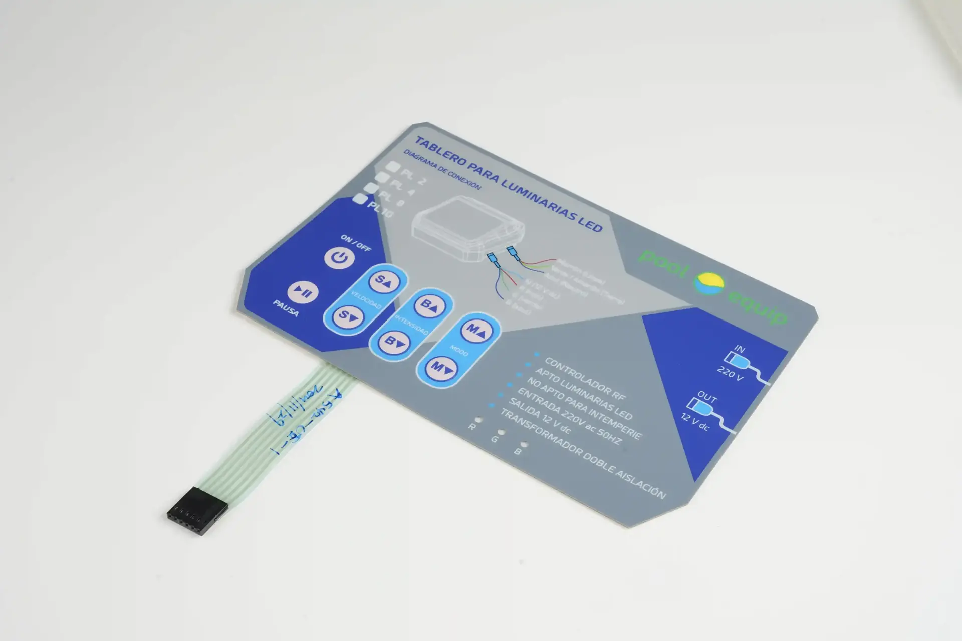
The product face is only the visible start of the boundary. The installed drawing must continue through the tail, connector, mounting plane, and enclosure.
Operator face and legends
- Field path
- UV, grit, cleaners, standing water, and repeated presses attack the visible film and printed information.
- Release decision
- Release the film, hard coat, texture, print system, key geometry, and window finish against the named exposure.
- Evidence
- Inspect color, readability, haze, cracks, key response, and surface damage after conditioning.
Perimeter and corners
- Field path
- Water can wick between laminated layers where seal land narrows, corners lift, or runoff remains against an edge.
- Release decision
- Set continuous land width, corner geometry, adhesive or gasket continuity, edge protection, and drainage on the drawing.
- Evidence
- Inspect every corner and edge on the installed sample, including areas close to fasteners or enclosure steps.
Windows and cutouts
- Field path
- Displays, LEDs, vents, screws, and emboss transitions interrupt the otherwise continuous operator face.
- Release decision
- Assign overlap, clear adhesive, bezel, gasket, transparent film, and sealed-subassembly ownership for every opening.
- Evidence
- Expose and inspect each opening in the assembled state, including optical appearance and powered function where applicable.
Flexible-tail exit
- Field path
- The tail can create a slot, stressed adhesive edge, fold, or capillary route directly into the electronics cavity.
- Release decision
- Control exit location, slot geometry, filler or local gasket, bend radius, strain relief, service motion, and dry-zone boundary.
- Evidence
- Test the actual installed bend and restraint, then inspect both sides of the exit instead of testing a loose flat switch.
Connector and cable entry
- Field path
- An unsealed connector, cable, gland, or mating half can carry water around a correctly laminated switch.
- Release decision
- Name who supplies and seals the connector, boot, gland, potting, drip loop, harness restraint, and mating interface.
- Evidence
- Expose the connected assembly with its production cable route and inspect the complete path into the enclosure.
Mounting plane and enclosure joint
- Field path
- Warp, texture, paint, ribs, contamination, uneven fastener load, or poor gasket compression can reopen the boundary.
- Release decision
- Release flatness, surface preparation, gasket land, adhesive pressure, hardware pattern, torque or bonding method, and assembly sequence.
- Evidence
- Use the intended housing, hardware, process, and orientation for fit, exposure, and post-test inspection.
Send the water paths, mounting surface, tail route, and unresolved sealing decisions for an engineering review.
Select the interface construction around the equipment
The application decides more than the overlay material. Key height, electronics density, night visibility, service access, and enclosure ownership determine which interface architecture creates the cleanest boundary.
Sealed membrane switch
Flat, low-profile controls with printed legends and a wipe-clean operator surface.
Coordinate tactile or non-tactile keys, perimeter adhesive, windows, tail exit, and the mounting plane.
Review product >Silicone rubber keypad
Raised keys, stronger finger location, glove use, and a molded flange or keymat integrated with a housing.
Coordinate keypad web, bezel clearance, PCB contacts, compression, gasket geometry, and cable protection.
Review product >PCB or FPC membrane interface
Dense routing, LEDs, components, controlled connectors, shielding, or rigid support behind a thin front.
Coordinate component height, bend zones, stiffeners, grounding, connector retention, and sealed enclosure space.
Review product >Complete HMI assembly
Projects where display, bezel, carrier, gasket, front panel, PCB, connector, and mounting must arrive as one released module.
Define module ownership, datums, optical checks, hardware, cable exit, service state, and finished-equipment validation.
Review product >Qualify the installed assembly before production release
A loose switch can prove continuity and appearance, but it cannot reproduce housing flatness, gasket load, tail strain, cable entry, drainage, or exposure orientation. The approval article must represent the installation that will be manufactured.
- 01
Map the boundary
Mark face, edges, openings, tail slot, connector, vent, enclosure joint, and intended dry zone on the assembly drawing.
- 02
Close the construction
Release materials, print, windows, circuit, key feel, adhesive or gasket, tail, connector, housing surface, and assembly method.
- 03
Build the installed sample
Apply the production-intent interface to the intended enclosure or an approved fixture with the same datums, load, and cable route.
- 04
Run and record acceptance
Use the defined exposure and inspect appearance, adhesion, operation, electrical state, internal evidence, recovery, and drawing revision.

What JASPER controls in production
JASPER manufactures the released interface stack and records the component checks named on the project drawing. Finished-equipment ingress, electrical safety, field life, software, and regulatory approval remain tied to the OEM assembly and validation plan.
- Revision control
- Released artwork, circuit master, materials, dimensions, and approved sample.
- Process control
- Printing, circuit production, precision cutting, lamination, and assembly to the agreed route.
- Functional checks
- Continuity, key map, connector, and other component checks where specified.
- Release evidence
- Visual, dimensional, packing, and project-specific inspection records defined before production.
Continue the engineering review
Use the product and design pages below to close construction details without turning this application page into a duplicate product catalog.
Waterproof Membrane Switches
Review sealing paths, enclosure boundaries, and component construction in product detail.
Open resource >IP65 vs IP67 Design
Separate spray and temporary-immersion targets before writing the sample protocol.
Open resource >Membrane Switch RFQ Checklist
Organize the drawing, exposure, connector, quantity, and approval inputs needed for a useful supplier review.
Open resource >Membrane Switch Materials
Compare films, inks, circuits, windows, adhesives, and support layers by exposure.
Open resource >Send the outdoor equipment package before tooling
A useful quotation identifies the installed boundary and the evidence required at sample approval. Early drawings are acceptable when they show what is fixed and what can still change.
Open Outdoor Project Form- equipment use, installation location, mounting orientation, and operator conditions
- front-panel and enclosure drawings with material, finish, flatness, openings, and hardware
- rain, spray, washdown, pooling, immersion, UV, temperature, chemical, salt, and abrasion inputs
- target IP or buyer test method with direction, duration, powered state, and acceptance
- key layout, tactile preference, glove use, legends, windows, indicators, and backlighting
- tail exit, bend route, slot, connector, cable, strain relief, venting, drainage, and service access
- prototype quantity, annual estimate, sample deadline, inspection records, labeling, and packaging
Outdoor Waterproof Membrane Switch FAQ
What is the difference between a water-resistant and waterproof membrane switch?
The difference is the defined exposure and the tested assembly. A panel that survives wiping or rain is not automatically suitable for water jets or temporary immersion. Specify the water source, direction, duration, installation, and acceptance method before assigning a project target.
Should an outdoor membrane switch be specified as IP65 or IP67?
Choose the target from the equipment exposure. IP65 addresses a water-jet condition, while IP67 addresses temporary immersion under its own conditions. One result does not replace the other, and both depend on the complete installed interface and enclosure used for the test.
Can the flexible tail and connector be sealed for outdoor use?
Yes, when the drawing controls the tail exit, slot, local filler or gasket, bend radius, strain relief, connector or gland, cable route, and intended dry zone. The installed tail and mating connection must be included in the sample review.
Which overlay material is best for an outdoor membrane keypad?
There is no universal outdoor overlay. Material selection depends on UV, temperature, chemicals, abrasion, key construction, window clarity, print system, and expected appearance. Approve the selected film and print stack against the named project exposure.
Does JASPER validate the finished equipment IP rating?
JASPER can manufacture the released interface and support agreed component or installed-sample checks. A finished-equipment IP result depends on the complete enclosure, gasket or adhesive, hardware, cable entries, vents, assembly process, test article, and specified external test method.
What should an OEM send for an outdoor waterproof membrane switch quote?
Send the panel and enclosure drawings, mounting surface, openings, tail and connector route, exposure and IP target, chemicals, UV and temperature inputs, key and lighting requirements, sample quantity, annual estimate, and the evidence required for approval.