
Mat outline
ControlRelease finished dimensions, corners, cutouts, holes, tabs, datums, install direction, and no-go zones.
Failure modeThe sensor interferes with seams, foam grooves, heaters, vents, or frame features.
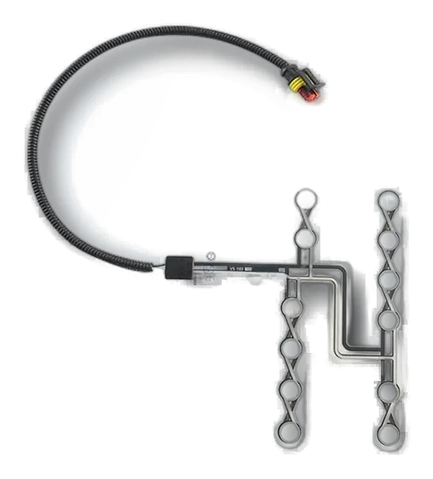
A seat occupancy sensor mat is a thin pressure-sensitive or contact-responsive component installed under foam, inside the cushion, below upholstery, or within another released seat layer.
The words mat and pad describe physical form, not one fixed sensing technology. The project still needs to define whether the customer electronics expect a contact state, resistance-related response, or another confirmed input.
JASPER supplies the released sensor component. Seat classification, reminder logic, calibration, diagnostics, and vehicle approval remain with the OEM, Tier 1, or system owner.
Most sample loops come from an incomplete seat boundary or validation condition.
Release finished dimensions, corners, cutouts, holes, tabs, datums, install direction, and no-go zones.
Failure modeThe sensor interferes with seams, foam grooves, heaters, vents, or frame features.
Mark the intended load area and the regions that must not trigger.
Failure modeThe mat detects an edge or object but misses the normal seated posture.
Name the exact location relative to foam, trim, support, heaters, ventilation, and adhesives.
Failure modeThe same mat responds differently after the stack changes.
Define contact, pressure, resistance-related, or another confirmed behavior with a named fixture.
Failure modeA vague trigger-force callout cannot be reproduced.
Control exit direction, bend boundary, reinforcement, cable length, restraint, and connector position.
Failure modeAssembly folds or pulls the conductor at the cushion edge.
Approve occupied, empty, preload, edge-load, object, repeated install, and routing cases.
Failure modeA flat-bench pass is mistaken for installed-seat approval.
The drawing should let the seat supplier install the mat in the same location and orientation every time.
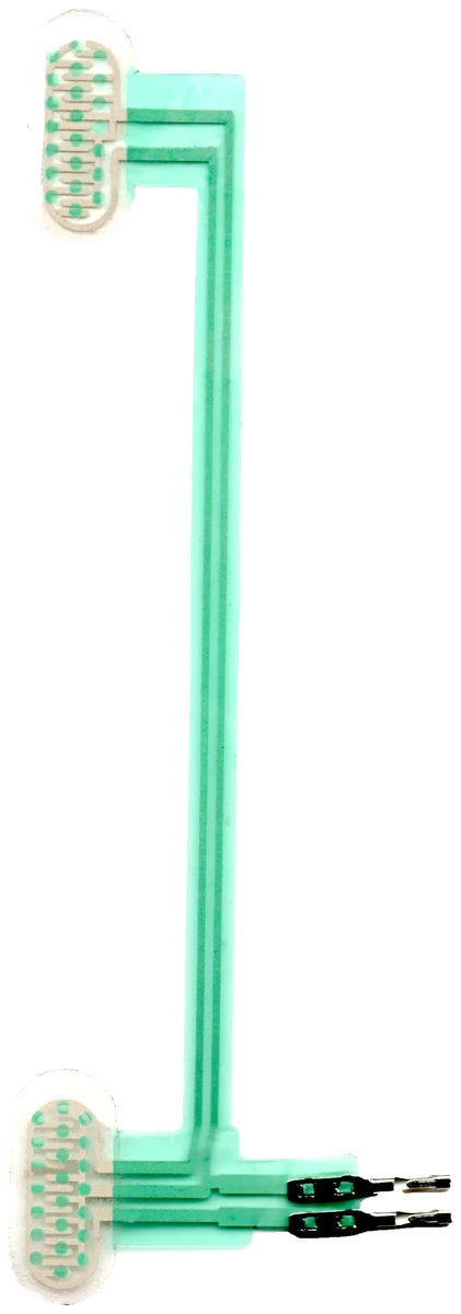
Seat foam spreads, concentrates, and redirects pressure. A nominal center point is not enough when bolsters, trim seams, support ribs, heating layers, and posture change the real load path.
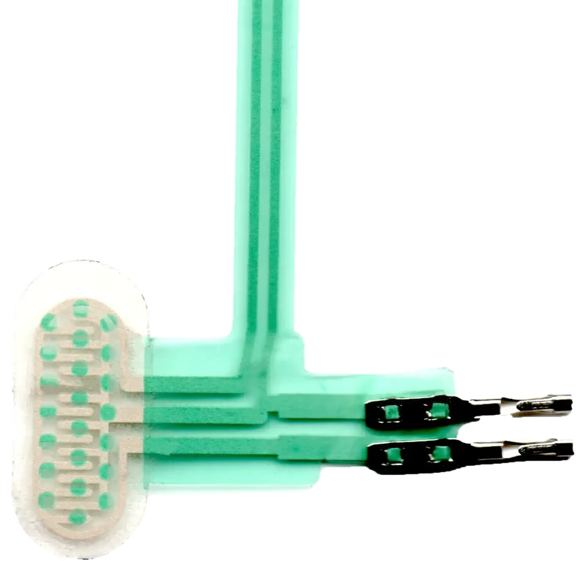
The transition from a flexible mat to a tail, wire, or connector is often the highest-strain area. Route it away from hinges, rails, brackets, foam cuts, trim pulls, and service access.
Review cushion section, foam behavior, upholstery tension, support, sensing zone, and installation boundary.
Release sensing principle, signal expectation, tail direction, cable protection, connector, and test access.
Check fit, false activation, occupied response, cable strain, connector fit, and repeatability in the real seat.
Lock drawing, material stack, circuit, connector, inspection, packaging, retained sample, and revalidation triggers.
Check trim preload, foam compression, hard support points, object placement, active-zone size, and installed orientation.
Review the real load path, posture range, foam thickness, mat position, zone coverage, and fixture assumptions.
Inspect cushion-edge bends, assembly pulls, frame contact, reinforcement, lead restraint, and connector mounting.
Compare foam, trim tension, installation position, sensor revision, connector fit, and sample conditioning.
The mat can be adapted to different seat packages when the system owner defines the intended input and validation.
Seat-specific mats for a defined passenger load zone and protected harness route.
Single or multiple mat layouts for bench, split, or module seating.
Project-defined seat-state component for specialty vehicle or equipment seating.
Repeated seat modules with controlled installation and cable protection.
Custom cushions where outline, active area, connector, and serviceability differ from automotive seats.
A top view plus one seat section is usually more useful than a generic sensor specification.
It may sit under foam, inside the cushion, below upholstery, above a support layer, or inside a seat module. The released drawing must name the exact layer and orientation.
Yes. JASPER can review the finished outline, cutouts, sensing zones, non-sensing areas, tail exit, cable, connector, label, and packaging.
Usually not without evidence. Cushion geometry, foam, trim tension, support, passenger posture, cable routing, and installation method can change the required layout.
Approve the released component and the installed seat under named occupied, empty, preload, false-trigger, routing, conditioning, and repeat-installation cases.
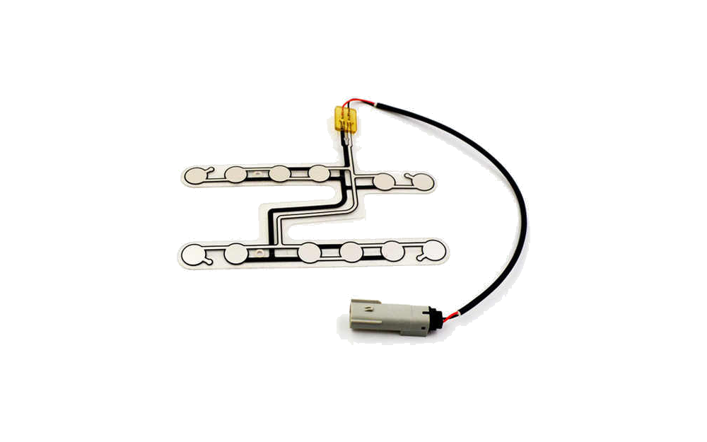
Compare the complete family by sensing principle, application, and supplied component boundary.
Review Resource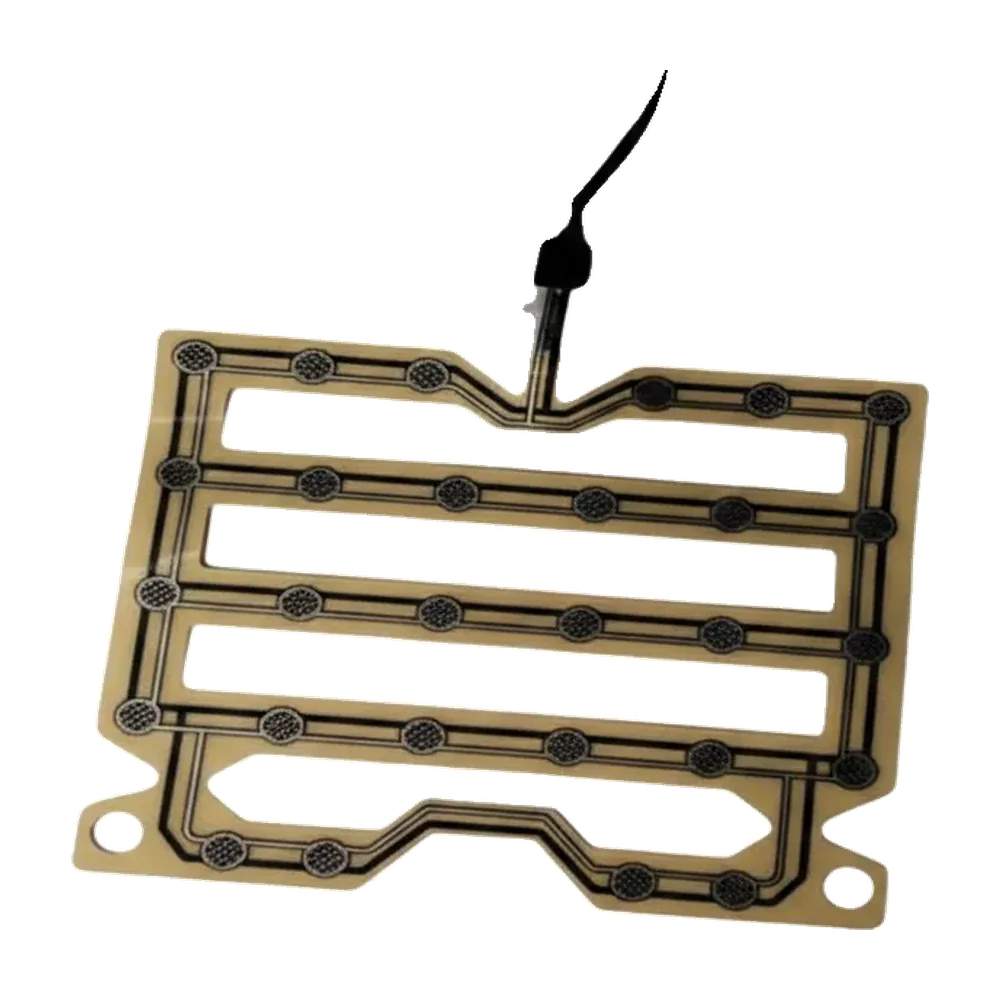
Use the pressure-focused route when response and load-path evidence are the main decisions.
Review Resource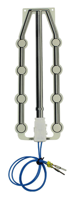
JASPER can review the outline, sensing zone, installation layer, tail, cable, connector, component evidence, and production controls for your released seat package.
Share the project basics. JASPER will review the stack, materials, connector, quantity, and production risks.