Dongguan, Guangdong 523927, China[email protected]+86 136 3262 5290
Home / Products / Membrane Switches / Waterproof Membrane Switches

Waterproof Membrane Switches

Custom sealed interfaces engineered around every water path. JASPER coordinates the overlay, laminate edge, windows, tail exit, connector boundary, gasket or adhesive, enclosure surface, drainage, and production-intent test before tooling.

Sealed custom membrane switch with flexible tail on a transparent background

Start with exposure, not the rating label.

The same front panel can face a damp cloth, wind-driven rain, temporary immersion, or repeated hot washdown. Those conditions create different paths, loads, materials questions, and acceptance evidence.

01

Wipe-down and liquid cleaning

Define
Which fluids contact the face, edges, windows, and housing joint?
Design focus
Overlay compatibility, edge protection, window seals, drainage, and residue.
Sample evidence
Repeated installed cleaning cycles plus visual and functional inspection.
02

Rain, splash, spray, or hose

Define
From which directions can moving water reach the panel and tail exit?
Design focus
Perimeter seal, corners, cutouts, tail route, connector entry, and runoff.
Sample evidence
Production-intent assembly exposed from the defined directions.
03

Temporary immersion

Define
Which assembled surfaces and joints remain below water, and for how long?
Design focus
Continuous boundary, trapped air, capillary paths, pressure change, and recovery.
Sample evidence
Agreed immersion protocol followed by internal and electrical inspection.
04

Washdown and process chemistry

Define
What pressure, temperature, chemistry, frequency, and powered state apply?
Design focus
Material compatibility, jet access, enclosure joints, drainage, and service wear.
Sample evidence
Buyer-defined wash sequence on the installed interface and housing.

Water finds the weakest of six interfaces.

Treat each route as a separate engineering decision. Closing one path does not prove that the next edge, opening, tail, connector, or housing joint is contained.

01

Front overlay surface

Water path

Water, cleaner, abrasion, and standing droplets reach the operator face.

Containment decision

Select a compatible film, ink system, window structure, and surface finish.

Installed proof

Inspect graphics, windows, keys, and function after the defined exposure.

02

Perimeter laminate edge

Water path

Water reaches exposed layer edges, corners, adhesive lands, and local gaps.

Containment decision

Set edge geometry, seal width, corner radius, adhesive continuity, and drainage.

Installed proof

Section or inspect the edge and check for wicking after exposure.

03

Windows and cutouts

Water path

Display windows, LEDs, vents, hardware holes, and emboss transitions interrupt the face.

Containment decision

Define overlap, clear adhesive, gasket, bezel, or sealed subassembly ownership.

Installed proof

Check each opening in the assembled and powered state.

04

Flexible-tail exit

Water path

The tail can create a slot, fold, capillary route, or stressed adhesive edge.

Containment decision

Control exit direction, slot geometry, seal land, bend radius, strain, and service motion.

Installed proof

Test the actual tail route and inspect both sides of the exit.

05

Connector or cable entry

Water path

Water may bypass the switch through an unsealed connector, cable, or mating interface.

Containment decision

Assign connector sealing, boot, gland, potting, drip loop, and mating responsibility.

Installed proof

Expose the complete connected assembly, not only the switch tail.

06

Housing joint and mounting plane

Water path

Warp, texture, fastener gaps, adhesive contamination, or uneven load can open the seal.

Containment decision

Release flatness, gasket land, surface preparation, compression, and assembly process.

Installed proof

Use the production enclosure, hardware, torque or bonding method, and inspection plan.

The enclosure is part of the waterproof membrane switch.

The seal runs from the operator face through the laminate edge and mounting boundary into the housing. Tail routing, connector protection, drainage, and assembly load must remain inside that controlled path.

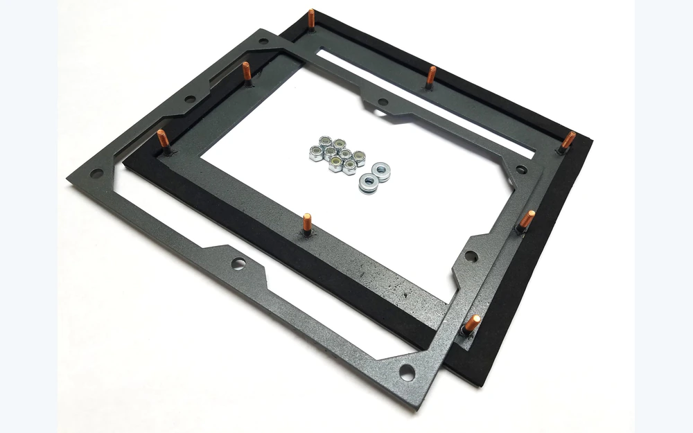
  • Keep the gasket or adhesive land continuous around openings and corners.
  • Do not route the tail through a slot that bypasses the protected cavity.
  • Define where water drains instead of allowing it to collect against an edge.
  • Check enclosure flatness and surface condition before assigning compression.
Graphic overlayPerimeter sealCircuit and spacerMounting gasketProduction enclosure

Prove the target before a part ships.

Use the required standard and buyer protocol to define exact conditions. The page below separates common exposure families without claiming that one result transfers to another.

SPLASH

Splash or spray exposure

Buyer defines

Define direction, flow, duration, mounting angle, powered state, and acceptance.

Sample proves

Installed sample stays functional and shows no unacceptable ingress at controlled boundaries.

JET

Water-jet exposure

Buyer defines

Define nozzle or equipment method, distance, direction, duration, temperature, and vulnerable joints.

Sample proves

Complete panel, housing, tail, and connector are inspected after the agreed sequence.

IMMERSION

Temporary immersion

Buyer defines

Define depth, duration, orientation, preconditioning, recovery, and internal inspection.

Sample proves

The assembled interface meets the project acceptance criteria after immersion.

PROJECT

Extended immersion or washdown

Buyer defines

Define every condition in the project test protocol; do not infer it from another rating.

Sample proves

Production-intent evidence matches the released construction and installation process.

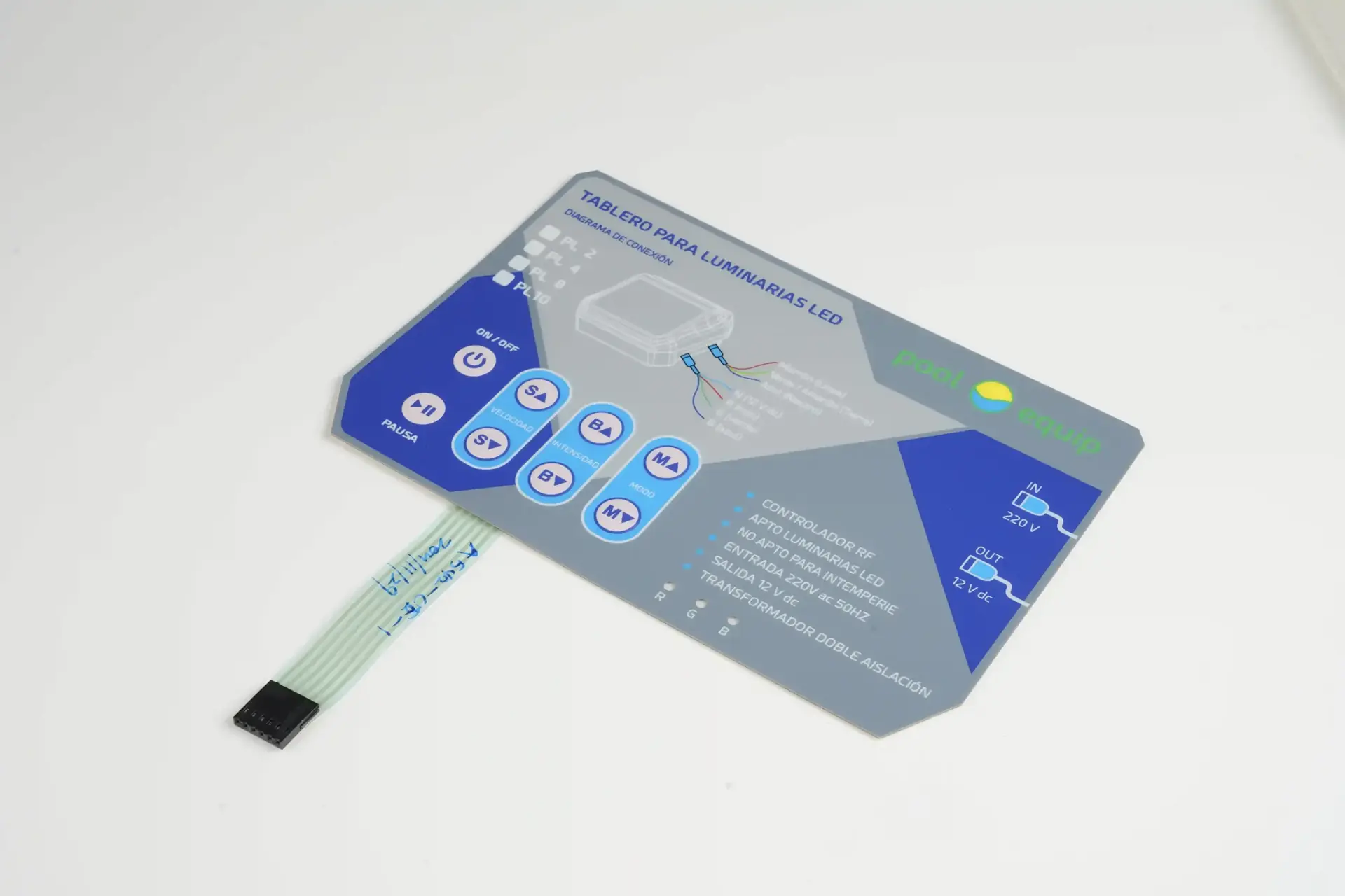
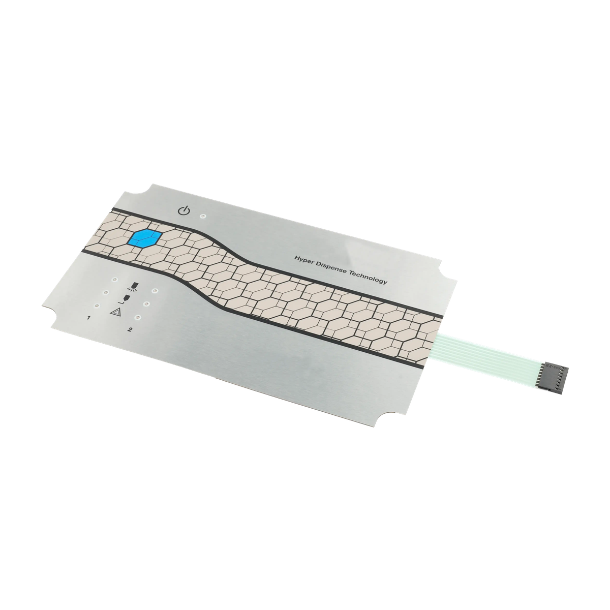
Custom membrane switch panel showing the flexible tail, connector, perimeter, and mounting outline

A flat switch cannot rescue an uncontrolled housing.

Surface waviness, narrow corners, recessed bosses, irregular texture, contaminated adhesive lands, or uneven fastener load can interrupt an otherwise sound perimeter. Review the mounting plane before releasing the switch outline.

Mounting planeFlatness, steps, texture, paint, release agents, and local ribs.
Seal landContinuous width around corners, windows, fasteners, and the tail exit.
Closure loadFastener pattern, bond pressure, gasket recovery, and service access.
Water managementSlope, drain route, vent path, pooling zones, and cable drip loop.

Trace the path before changing the material.

A leak report is useful only when it identifies the entry point, travel path, internal evidence, and assembly state. These four patterns are common starting points for diagnosis.

01

Edge wicking

Moisture appears along a laminate edge or corner.

Ask: Is the perimeter land continuous, clean, wide enough for the geometry, and protected from pooling?
02

Tail capillary entry

Moisture follows the tail or appears behind the exit slot.

Ask: Does the installed bend, strain, slot, or adhesive transition create a capillary route?
03

Connector bypass

The switch face stays dry while moisture enters through the harness side.

Ask: Who owns the mating connector, gland, boot, potting, drip loop, and cable route?
04

Housing gap

Ingress changes with fastener position, surface variation, or assembly method.

Ask: Is the mounting plane flat and is closure load distributed across the entire seal boundary?

Match the sealed interface to the real operating environment.

Application names do not select an IP target. Capture the actual water source, cleaning process, installation, and acceptance method for each project.

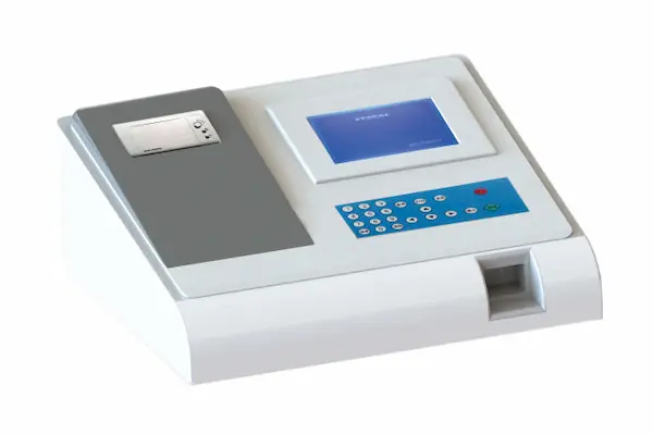
Medical equipment with an integrated membrane switch operator interface

Medical and laboratory equipment

Exposure inputs

Frequent wipe-down, disinfectant contact, seams, windows, and hygiene requirements.

Release focus

Define approved chemicals, dwell time, cycle count, residue, and post-cleaning inspection.

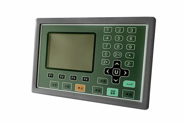
Industrial control interface with display, keypad, and sealed front panel

Industrial controls and machinery

Exposure inputs

Directed water, process debris, temperature change, chemistry, and repeated production shifts.

Release focus

Define jet access, powered state, drainage, enclosure joints, and connector protection.

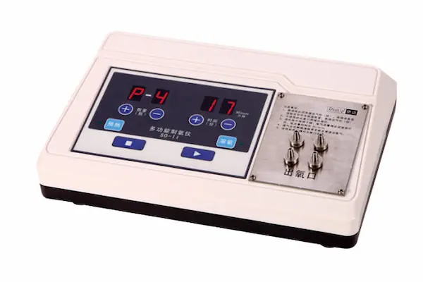
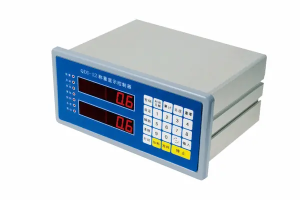
Bench instrumentation with a membrane keypad and dual digital display

Test and measurement instruments

Exposure inputs

Bench spills, field handling, cleaning fluids, display openings, and repeated key operation.

Release focus

Coordinate window seals, key geometry, tail routing, housing flatness, and cleaning evidence.

Mobile electronic equipment with a display and membrane keypad interface

Outdoor and mobile electronics

Exposure inputs

Rain, splash, condensation, dust, temperature cycling, cable entry, and enclosure breathing.

Release focus

Coordinate runoff, venting, edge protection, tail exit, housing joint, and service access.

Approve the production-intent interface, not a loose switch.

Install the released switch on the intended housing with the real gasket or adhesive, tail route, connector, fasteners or bonding process, and exposure orientation. Then inspect function and every controlled boundary.

  • released enclosure surface, openings, and mounting hardware
  • production gasket or adhesive and documented installation process
  • actual tail bend, slot, strain relief, connector, and cable route
  • defined exposure direction, duration, temperature, chemistry, and powered state
  • visual, electrical, internal-ingress, recovery, and post-test acceptance
Plan Installed Sample Review
JASPER operator visually inspecting membrane switch sheets under production lighting
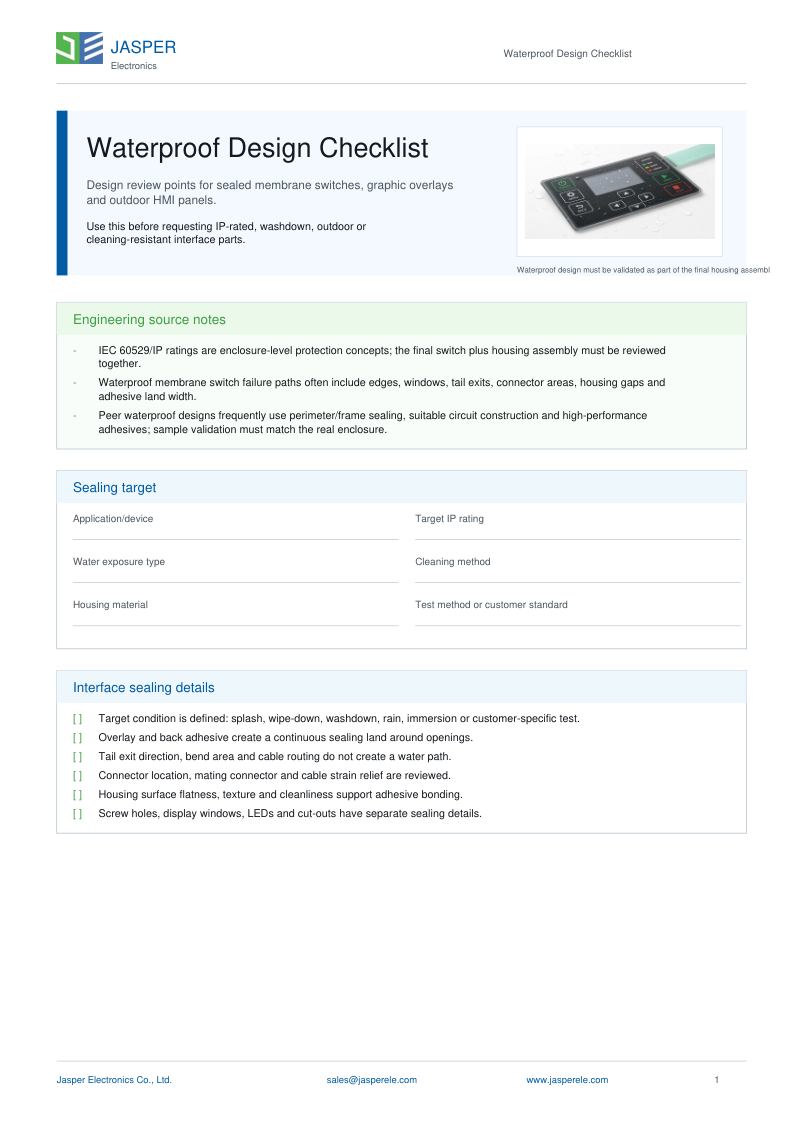
JASPER Waterproof Design Checklist cover

Waterproof Design Checklist

Prepare the exposure, target rating, enclosure drawing, perimeter land, windows, tail route, connector, gasket or adhesive, drainage, assembly process, and sample evidence before tooling.

Waterproof Membrane Switch FAQ

What makes a membrane switch waterproof?

A waterproof membrane switch depends on the complete installed sealing boundary: the overlay, laminate edge, windows, tail exit, connector or cable entry, mounting gasket or adhesive, enclosure surface, and assembly process. A sealed-looking face alone does not protect every water path.

Is an IP65 membrane switch also IP67?

Not automatically. IP65 and IP67 address different water exposures, so evidence for one target does not prove the other. Define the required exposure and approve a production-intent interface assembly using the matching test method.

Can a flexible tail exit be sealed against water?

Yes, but the design must control the exit location, adhesive land, bend radius, strain, capillary path, enclosure slot, and any local gasket or potting boundary. The tail should be tested in its installed route rather than as a loose flat sample.

Does the enclosure affect waterproof membrane switch performance?

Yes. Surface flatness, gasket land, corner geometry, fastener spacing, surface finish, venting, drainage, and installation pressure can open or close leak paths. The switch and housing should be reviewed as one sealing system.

How should a washdown membrane switch be specified?

Define where water comes from, spray or jet direction, duration, distance, temperature, cleaning chemistry, frequency, powered state, drainage, and acceptable post-test operation. Then select a construction and evidence plan around those conditions.

What should an OEM send for a waterproof membrane switch quotation?

Send the panel drawing, housing material and surface, cutouts, tail route, connector location, gasket or adhesive concept, target exposure, cleaning method, chemicals, sample quantity, and the installed test or acceptance requirement.

Continue the Waterproof Membrane Switch Design Review

Send the housing drawing before the sealing boundary is locked.

JASPER can review the perimeter, openings, tail route, connector, and installed evidence plan together.

Request Waterproof Switch Quote