
Membrane switch layers are the ordered films, adhesives, circuits, and optional modules that form a sealed, low-profile keypad. The stack-up sets actuation feel, thickness, sealing path, electrical routing, and enclosure fit before any single material grade is frozen.
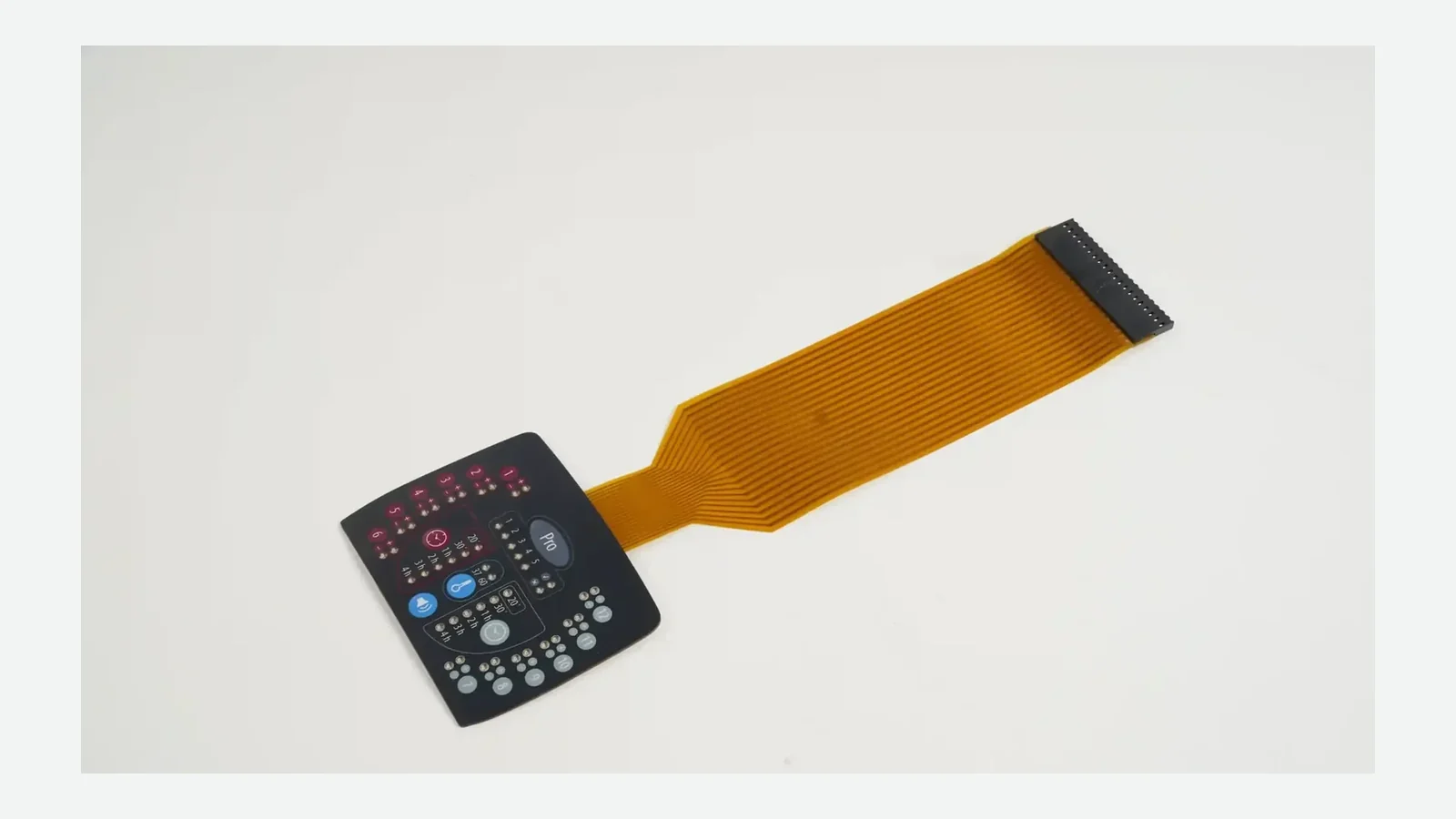
1. What membrane switch layers are
Membrane switch layers are the discrete functional sheets in a custom switch assembly. A membrane switch opens or closes a conducting path and requires at least one contact made of or attached to a flexible substrate, with thin layers joined by pressure-sensitive adhesives (PSA). Across controlled OEM design packages, those sheets are not interchangeable labels. Each layer owns a job—graphic protection on PET or polycarbonate, isolation gap in the spacer, silver or copper conductor path on flex or PCB, bond to the enclosure with acrylic PSA, or air management for a metal snap dome.
What the stack decides
| Decision | Controlled mainly by |
|---|---|
| Operator feel and travel | Overlay stiffness, emboss, dome or flat contact, spacer pocket, support flatness |
| Overall thickness and bend | Film gauges, adhesive build-up, rigid backer, LED or shield inserts |
| Electrical continuity path | Upper/lower circuit technology, contact geometry, tail, connector |
| Environmental path | Perimeter adhesive, windows, tail exit, gasket features, enclosure interface |
| Assembly fit | Outline, windows, mounting adhesive, support plate, tail exit direction |
What a stack is not
- A single polymer acronym (“PET” or “PC”) without grade, finish, and thickness basis
- An IP claim written on a free panel with no enclosure or test article
- A front-view graphic that omits spacer openings, vent concept, and connector orientation
Treat the stack as one controlled bill of materials (BOM). If two suppliers invent different constructions under one part number, RFQ prices and first-article inspection (FAI) results cannot be compared. A controlled revision on the layer schedule is the comparison baseline.
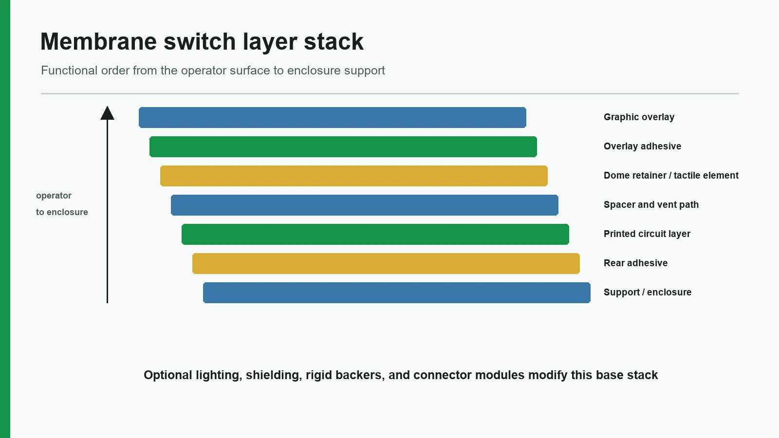
2. Canonical membrane switch stack up
2.1 Language-neutral exploded diagram
OPERATOR FACE
1. Graphic overlay (printed second surface; optional hard coat / emboss / window)
2. Overlay adhesive (selective openings at keys)
3. Optional dome retainer / metal or poly dome array
4. Optional upper circuit (printed silver, carbon, or copper flex)
5. Spacer with key openings (+ vent channels when tactile air must move)
6. Lower circuit (printed flex, FPC, or PCB contact layer)
7. Optional shield / ESD layer / LED or light-guide insert
8. Rear adhesive / gasket features
9. Optional rigid support (aluminum, FR4, plastic plate)
10. Enclosure mounting surface
Tail exit → stiffener → connector → controller
Diagram description for illustration: cross-section of a flexible tactile keypad showing overlay, selective overlay adhesive, metal dome in a spacer pocket with a side vent channel, lower circuit pads, rear adhesive, and a support plate, with the flexible tail leaving one edge toward a ZIF-style connector.
2.2 Base membrane switch components
| Layer / component | Typical materials (examples, not defaults) | Primary function | Drawing signal that must exist |
|---|---|---|---|
| Graphic overlay | Polyester or polycarbonate film grades; hard coats; second-surface inks | Legend, wear surface, first environmental barrier | Film family/grade or approved equivalent; finish; print side; emboss map |
| Overlay adhesive | Acrylic PSA, selective die-cut | Bonds overlay; keeps key zones free to flex | Openings aligned to keys; thickness basis; adhesive family |
| Spacer | Polyester carrier with adhesive faces | Maintains open gap until actuation | Key cutouts; web width; vent concept if tactile |
| Circuit layer(s) | Silver/carbon on PET; copper FPC; PCB pads | Conductive path and contact geometry | Trace material; contact style; pinout ownership |
| Rear adhesive | Transfer tape or double-coated PSA | Mounts assembly to enclosure or plate | Substrate list; surface energy class; edge width |
| Tail + connector | Integral flex tail; stiffener; ZIF/LIF/crimp | Routes signals off the panel | Exit direction; bend zone; pitch; contact side |
Overlay and graphic films are offered as grades and finishes, not as a single polymer word (Commercial film selector guide). Call out grade or approved equivalent when the ABS, aluminum, powder-coat, or polycarbonate enclosure, cleaning chemistry, or flex path is known.
2.3 Industry-typical construction ranges (verify on the project)
OEM design packages and converter guides often start from the ranges below. They are industry-typical planning bands, not guarantees. Film grade, dome series, process capability, and the enclosure change the correct numbers. Confirm on the approved stack before tooling and before any public claim on a datasheet.
| Parameter | Industry-typical planning band | What actually freezes the number |
|---|---|---|
| Overall flexible stack thickness (no thick PCB backer) | About 0.6–2.5 mm for many industrial keypads; backlit, rigid-backed, or PCB hybrids run thicker | Layer gauges + adhesives + dome height + support |
| Graphic overlay film | Polyester often about 0.125–0.188 mm (≈5–7 mil) class; polycarbonate often specified thicker when impact or formability leads | Grade, hard coat, emboss, chemical list |
| Emboss (if used) | Commonly on the order of a few tenths of a millimeter above the flat face | Operator feel sample on final support |
| Metal dome force (series-dependent) | Many industrial keys land roughly in the low-hundreds of grams-force class; medical and gloved panels may sit higher or lower | Named dome series + force tolerance + support |
| Spacer / open gap | Sized to dome height or flat-contact travel with a small preload margin | Dome supplier geometry + feel sample |
| Actuation travel (tactile) | Often well under 1 mm for metal-dome flex panels | Dome + emboss + support stack |
| Rear adhesive contact | Full-face or perimeter bond; edge width set by sealing and peel risk | Enclosure flatness, coating, washdown claim |
| Flexible tail bend | Static bends kept gentle relative to stack thickness; stiffener length set by connector | Connector drawing (pitch, flex thickness, contact side) |
| Life target (order-of-magnitude) | Non-tactile silver-flex and well-supported dome systems are often discussed in the 10⁵–10⁶+ cycle class in OEM RFQs; only a named test method and dome/pad system make the number real | Dome series, plating/venting, force, environment |
Use the table to shortlist a stack, then replace every band with project values on the controlled drawing. Do not publish a single number from this table as a product specification without that project lock.
3. How membrane switch construction works in use
Membrane switch construction turns a finger load into a temporary electrical closure, then returns the surface to open.
- Load — The operator presses a key zone on the graphic overlay. Embossing height and PET or PC stiffness shape how force spreads into the pocket.
- Deflection — The overlay and any metal or poly dome move into the spacer opening.
- Contact — Conductive surfaces meet: dome to pad, upper circuit to lower circuit, or interdigitated poles under a shorting element on silver flex or copper FPC.
- Signal — The controller reads the closed path through the tail, stiffener, and ZIF/LIF connector.
- Release — Elastic recovery of the overlay and/or dome reopens the gap. Spacer thickness and web geometry keep adjacent keys from bridging.
3.1 Flat (non-tactile) path
Non-tactile stacks omit metal domes. Feedback comes from overlay travel, a soft poly dome, or external cues such as an LCD status line or a short tone. These builds can be thinner and quieter. They still need a defined spacer gap, contact geometry, and support flatness. “No dome” is not “no stack engineering.”
3.2 Tactile metal-dome path
Metal domes add snap and an audible or tactile click. When a dome is depressed, air under the dome is compressed unless a vent path exists; venting may run dome-to-dome in the spacer, through the top polyester material, or through the PCB or support. Without venting, tactile response can degrade. Use a centered flat-bottom actuator no more than about 25% of dome diameter where that geometry applies (Snaptron plating and venting page). The dome, pocket, actuator alignment, support, and vent are one subsystem—not a late BOM line.
3.3 Support and over-travel
A flexible circuit on soft foam or a warped ABS housing will feel inconsistent even when the printed silver stack is correct. Rigid aluminum or FR4 support, acrylic PSA contact, and any over-travel stop belong in the stack discussion before tooling freezes spacer dies.
4. Stack variants and optional membrane switch components
Optional modules change thickness, unit cost, sealing, and electrical noise behavior. Add them only when a product requirement—for example IEC enclosure sealing intent, EMI path planning, or low-light legends—is real.
| Variant / module | What is added or changed | Typical reason to use | Trade-off / failure if ignored |
|---|---|---|---|
| Metal-dome tactile | Domes + retainer + pocket + vent concept | Clear snap for gloved or high-attention tasks | Air trap, uneven force, seal conflict if vent is blocked |
| Non-tactile flat | No metal dome; defined flex gap | Quiet panels, low profile, high cycle without snap | Operators may over-press without external feedback |
| EMI / ESD shield | Conductive layer, grid, or foil with ground path | Noisy environments; ESD path planning | Thickness, stiffness, ground ownership; still equipment-level for IEC 61000-4-2 framing |
| Display / LED window | Clear window in overlay; mask layers | Readouts or indicators under the face | Haze, registration, adhesive in the optical path |
| Backlighting | Discrete LEDs, light-guide film, or EL insert; dead-front graphics | Low-light operation | Heat, pin count, light leakage, off-state appearance |
| Rigid support | Aluminum, FR4, or molded plate | Flat actuation; mechanical strength | Weight, outline tolerance, adhesive surface prep |
| PCB-backed contacts | PCB as lower circuit / dome land | Stable pads, mixed SMT | Thickness; connector strategy changes |
| FPC copper circuit | Copper flex instead of printed silver only | Current, fine pitch, flex life needs | Cost; bend radius; stiffener design |
| Extended gasket / seal features | Wider rear adhesive, foam, or gasket | Washdown or outdoor enclosure interface | Must match enclosure groove and test article—not a free-panel IP label |
4.1 Domes and the metal dome membrane switch path
Choose metal domes when the operator needs a crisp event. Coordinate dome diameter and force series with overlay emboss, spacer pocket, and support. Metal-dome pad systems use plating options such as electro-deposited nickel, hard gold (with reference to MIL-G-45204C Type II Grade C on their page), and ENIG with an IPC-4552 reference for lower life-cycle contexts; those notes exist to keep contact resistance stable over the intended life of the pad system. The dome and pad system remain the controlling design, not a generic “gold is always better” rule (Snaptron plating guidance).
4.2 Windows and dead-front graphics
Windows are stack features. Print-to-cut registration, adhesive clearances, and support of the window edge determine whether an LCD or LED window looks centered after assembly. Dead-front icons that must disappear when off need controlled translucency and backlight masking—again a multi-layer problem on the graphic overlay and any light-guide film (LGF).
4.3 Backlighting inserts
LED windows, light-guide film, and electroluminescent (EL) layers each insert thickness and electrical pins into the stack. Approve brightness and uniformity on the intended enclosure and viewing angle. A bright bench sample that leaks light around a poorly masked legend is a stack defect, not only an LED part-number issue on the BOM.
4.4 Shielding
Shield layers are membrane switch components with a ground path owner. IEC 61000-4-2:2025 is an equipment-level ESD test method. A copper or silver shield in the keypad can be part of the path; it does not replace system-level design and test of the finished equipment under the OEM’s EMC plan.
5. Specifications, standards, and decision boundaries
Use named standards to frame claims. Do not treat a material data sheet as a finished-equipment certificate.
| Standard / source | What it bounds | How to use it on a stack drawing |
|---|---|---|
| IEC 60529 | Degrees of protection provided by enclosures | State the test article (switch + enclosure + openings + tail path). Do not print “IP67 membrane” as a free component property (IEC 60529). |
| IEC 61000-4-2 | ESD immunity test methods for equipment | If ESD is a product requirement, define equipment-level targets and how the shield/ground ties in (IEC 61000-4-2:2025). |
| 3M 467MP (example) | 200MP acrylic for metals / high-surface-energy plastics | Example rear or structural adhesive family—not a default for every plastic housing (3M 467MP TDS). |
| 3M 9495LE (example) | 300LSE for LSE plastics and powder coats | Example when the enclosure is LSE or powder-coated; still validate on the real finish (3M 9495LE data). |
| 3M surface prep guidance | Clean, dry, unified surfaces; firm pressure | Installation process belongs next to adhesive callouts. |
| FPC connector drawings | Pitch, contact side, flex thickness, actuator style | Connector drawing controls tail design (TE product examples). |
| Commercial film selector | Film grades and finishes | Overlay specified as grade/finish system, not “PET only.” |
| Metal-dome venting and plating guidance | Air path and pad plating context for domes | Required notes on tactile stacks. |
Adhesive selection is a stack decision tied to the enclosure. Adhesive Transfer Tape 467MP uses 200MP acrylic and is positioned (200MP acrylic) toward metals and high-surface-energy plastics, and Double Coated Tape 9495LE (300LSE) toward low-surface-energy plastics and powder-coated paints (3M product data, public TDS sheets). That contrast is a reason to test the actual substrate—not a reason to copy a part number from the last project. Surface preparation still matters: clean, dry, unified surfaces and firm application pressure improve contact (3M bonding and assembly guidance).
6. When a recommended stack is the wrong choice
A “standard six-layer tactile stack” is not always correct. Stop and redesign when any of the following is true.
| Situation | Why the usual stack fails | Better direction (examples) |
|---|---|---|
| Enclosure cannot provide flat support | Domes feel mushy or uneven | Add rigid backer, redesign housing boss, or move to a construction that tolerates the support |
| Product needs near-silent keys | Metal-dome snap is unwanted noise | Non-tactile or soft poly feedback with display/beep confirmation |
| Perimeter seal forbids any vent strategy the tactile stack can use | Vent and IP claim conflict | Re-plan vent to a controlled internal volume, change tactile method, or change seal architecture |
| Very high flex or tight bend at the tail | Thick multi-layer tail cracks or exceeds connector thickness | Thin the circuit system; re-route; match TE-style connector thickness and contact side |
| Optical display dominates the face | Adhesive and circuit webs show in the window | Window-first stack with optical clearances and separate keypad zones |
| Controller expects copper flex geometry the silver print cannot meet | Resistance, pitch, or flex life mismatch | FPC or PCB hybrid with explicit pinout ownership |
| Cleaning chemistry attacks the chosen overlay family | Haze, ink loss, cracking | Change film grade/finish and re-validate cleaners—do not “hope PET is enough” |
Explicit non-recommendation: Do not freeze screens, spacer dies, and emboss tools while the stack is still a front-view PDF. Do not claim an IP code for a loose switch. Do not add a metal dome without a vent and support plan. Do not specify rear adhesive without the real enclosure material and coating.
7. Project inputs and sample approval checklist
7.1 Inputs to send with a proposed layer stack
| Input | Why it changes the stack |
|---|---|
| Enclosure material, coating, texture, flatness | Rear adhesive and support |
| Overall thickness budget and key travel target | Film gauges, dome, spacer |
| Tactile vs non-tactile intent; glove use | Dome series, emboss, force |
| Environment: liquids, dust, cleaners, UV, temperature range | Overlay, seals, adhesive |
| Electrical: matrix vs common, LED pins, shield ground | Circuit layers and tail |
| Tail exit, bend path, connector part or pitch/contact side | Tail and stiffener |
| Windows, dead-front, backlight type | Optical layers and masks |
| Sample quantity and acceptance tests | First-article plan |
7.2 Sample and test matrix (mount to the real enclosure)
| Check | What “pass” looks like | Related control |
|---|---|---|
| Visual / registration | Legends and windows align to datums; no adhesive in openings | Print-to-cut and stack registration |
| Actuation feel | Force and snap consistent across keys on final support | Dome, spacer, support |
| Continuity / isolation | Closed keys conduct; open keys stay open; no bridge | Circuit and spacer webs |
| Tail bend and connector mate | Tail reaches connector without crease; contact side correct | Tail geometry; TE-style connector rules |
| Edge seal observation | No lift or channel at perimeter under agreed exposure | Rear adhesive; enclosure prep |
| Lighting (if any) | Uniformity and off-state appearance acceptable in product orientation | Masks, LEDs, windows |
| Revision lock | Approved stack revision matches production BOM | Document control |
Laboratory or production quality testing should reference the same revision as the drawing package. Continuity, isolation, actuation, and visual checks are typical factory gates. Component-level checks do not replace finished-equipment validation when the product is a medical device under an ISO 13485 QMS, an automotive module under IATF 16949 expectations, or another regulated assembly.
8. Frequently asked questions
How many membrane switch layers does a typical panel use?
There is no single correct count. Flat non-tactile builds may use a short stack of overlay, adhesives, spacer, and one or two circuit films. Tactile, shielded, backlit, or rigid-backed assemblies add modules and can reach eight or more functional layers. Specify the function of each layer rather than a magic number.
What is the difference between membrane switch construction and a graphic overlay alone?
A graphic overlay is the visible face film. Membrane switch construction includes the isolation spacer, conductive circuits, rear mount, tail, and any tactile or lighting modules. An overlay without a defined electrical and mechanical stack is artwork, not a switch.
Do membrane switch components always include metal domes?
No. Metal domes are optional tactile elements. Non-tactile circuits close by flexing conductive layers together without a snap dome. Domes should be added only when the operator and product need that feedback.
How should venting appear on a membrane switch stack up drawing?
For tactile metal-dome stacks, show the air path concept: spacer channels between keys, a path through a carrier film, or a path through the board or support. If the product also claims a sealed perimeter, the vent strategy and the seal strategy must be reviewed together.
Can a membrane switch be called IP65 or IP67 from the stack alone?
Not rigorously. IEC 60529 classifies protection provided by enclosures. Any IP claim needs a defined assembly, openings, tail exit, and test method. The stack contributes sealing features; the enclosure and test article complete the claim.
Which adhesive belongs on the rear of the stack?
The adhesive that matches the real enclosure surface energy, texture, temperature, and cleaning exposure after proper surface preparation. Examples such as 3M 467MP (high-surface-energy / metal-oriented 200MP acrylic) and 3M 9495LE (300LSE for LSE plastics and powder coats) illustrate different positioning—not universal defaults.
When should the circuit be printed silver versus copper FPC or PCB?
Printed silver on polyester is common for low-profile flexible keypads. Copper FPC or PCB lands are chosen when pitch, current, flex life, or mixed SMT requirements exceed what the printed silver system should carry. The choice changes thickness, bend rules, and connector design.
What should be reviewed before approving a proposed layer stack?
Confirm layer order and thickness basis, tactile method and vent, circuit technology and pinout, tail exit and connector, rear adhesive versus enclosure, windows or lighting, sealing claim language, and the sample tests that will lock the revision. Incomplete packages produce incomparable quotes.
9. Review a proposed layer stack
If the construction is still open, freeze the operator scenario, enclosure surface, tactile intent, electrical interface, and sealing claim before cutting multi-layer tooling. Package the layer schedule, section view or exploded stack, TE-style connector detail (pitch, contact side, flex thickness), and sample acceptance list as one revision.
JASPER can review a proposed stack against those inputs as a manufacturer engineering check. The same checklist applies if another supplier builds the parts. Send the drawing package when the stack is proposed—not after screens and dies already assume a construction that the enclosure cannot support.
Technical References
- Source: 3M 467MP and 9495LE technical data. Accessed 2026.
- Source: 3M membrane switch construction guidance. Accessed 2026.
- Source: Covestro Makrofol and Bayfol Film Selector Guide. Accessed 2026.
- Source: Snaptron metal dome plating and venting guidance. Accessed 2026.
- Source: TE Connectivity FPC connector product drawings. Accessed 2026.
- Source: IEC 60529 enclosure protection classification. Accessed 2026.
- Source: IEC 61000-4-2 electrostatic discharge immunity testing. Accessed 2026.
- Source: ASTM F1578 membrane switch contact closure cycling practice. Accessed 2026.
Freeze the complete layer schedule before tooling
Send the proposed section view, tactile method, circuit, tail, connector, rear substrate, sealing path, and sample acceptance plan.