
Illuminated output
ControlDefine what should emit light, its visible boundary, color, powered state, unpowered state, and viewing condition.
Failure modeThe team approves brightness without agreeing what the key should look like.
A backlit silicone keypad must produce an approved powered and unpowered appearance through the selected silicone, color system, legend opening, LED layout, optical path, light block, PCB, housing, and viewing condition.
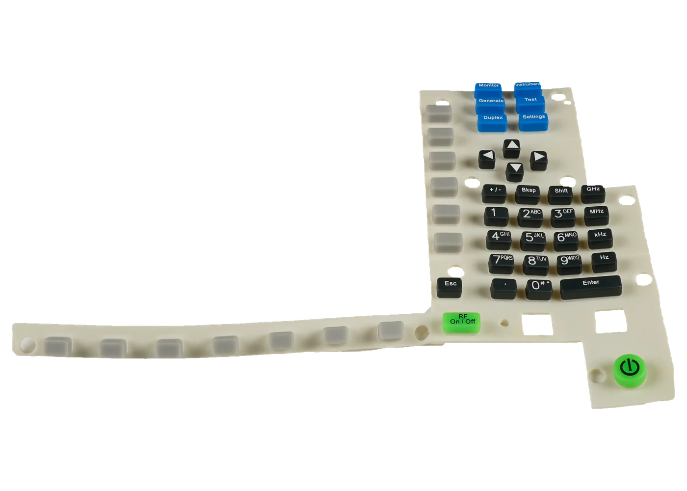
A backlit silicone keypad uses selected material and geometry to carry light from an LED or another source toward a controlled legend, symbol, window, outline, or illuminated area.
The result depends on the silicone base, molded thickness, pigment, coating opacity, legend opening, LED position, distance, angle, diffuser, circuit, spacer, enclosure, barriers, ambient light, and observer. A bright LED alone does not prove a readable keypad.
Use this route when illuminated output is the primary risk. Use the laser-etched route when coating and opened-legend control dominate, and use the assembly route when JASPER must also own the PCB, connector, carrier, and final optical function.
Hot spots, dim corners, glowing edges, and cross-lighting appear when one part of the optical path is released alone.
Define what should emit light, its visible boundary, color, powered state, unpowered state, and viewing condition.
Failure modeThe team approves brightness without agreeing what the key should look like.
Release base silicone, color or pigment, molded thickness, local geometry, transmission direction, and substitution control.
Failure modeA material change shifts brightness, color, or diffusion after tooling.
Control coating or printed block, coverage, thickness direction, color, gloss, edge, and adhesion.
Failure modeThe key glows through areas intended to remain dark.
Release vector artwork, scale, line width, position, process, edge quality, and registration.
Failure modeA clean drawing becomes a fuzzy or incomplete illuminated symbol.
Define LED package, color, output state, location, orientation, drive, PCB, distance, and heat boundary.
Failure modeA late PCB change creates hot spots or moves light away from the legend.
Review diffusion, spacer color, ribs, barriers, enclosure walls, neighboring keys, edge paths, and inspection.
Failure modeOne key lights adjacent keys or the perimeter instead of its intended symbol.
The optical specification should describe the visible output and test condition, then connect that result to the material, legend, LED, circuit, and enclosure.
| Decision | Options to Review | Release Question |
|---|---|---|
| Visible output | Legend, symbol, window, indicator, outline, full key, edge, or combined effect | What exact area should appear lit, dark, colored, or hidden in each state? |
| Base construction | Translucent, selected-color, multi-shot, insert, local window, or project-defined molded route | What material and thickness path carries or blocks the light? |
| Surface system | Opaque coating, printed block, laser-opened legend, protective coating, texture, gloss, or combined stack | What controls opacity, color, adhesion, wear, cleaner, and appearance? |
| LED system | Package, color, location, quantity, angle, output, drive, PCB, diffuser, and distance | Which released PCB and electrical condition create the approved sample? |
| Light blocking | Dark spacer, molded ribs, housing partitions, local shields, opaque walls, or geometry | How is cross-lighting, edge glow, and adjacent-key leakage prevented? |
| Optical evidence | Powered and unpowered first article, ambient, viewing angle, voltage, temperature, image, and retained sample | Which condition and reference authorize production and future changes? |
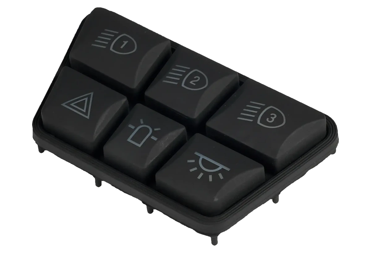
A tall, sloped, curved, or offset key changes how light reaches the visible symbol. Review the LED against the three-dimensional key, circuit height, spacer, housing wall, and operator viewing angle before locking the PCB.
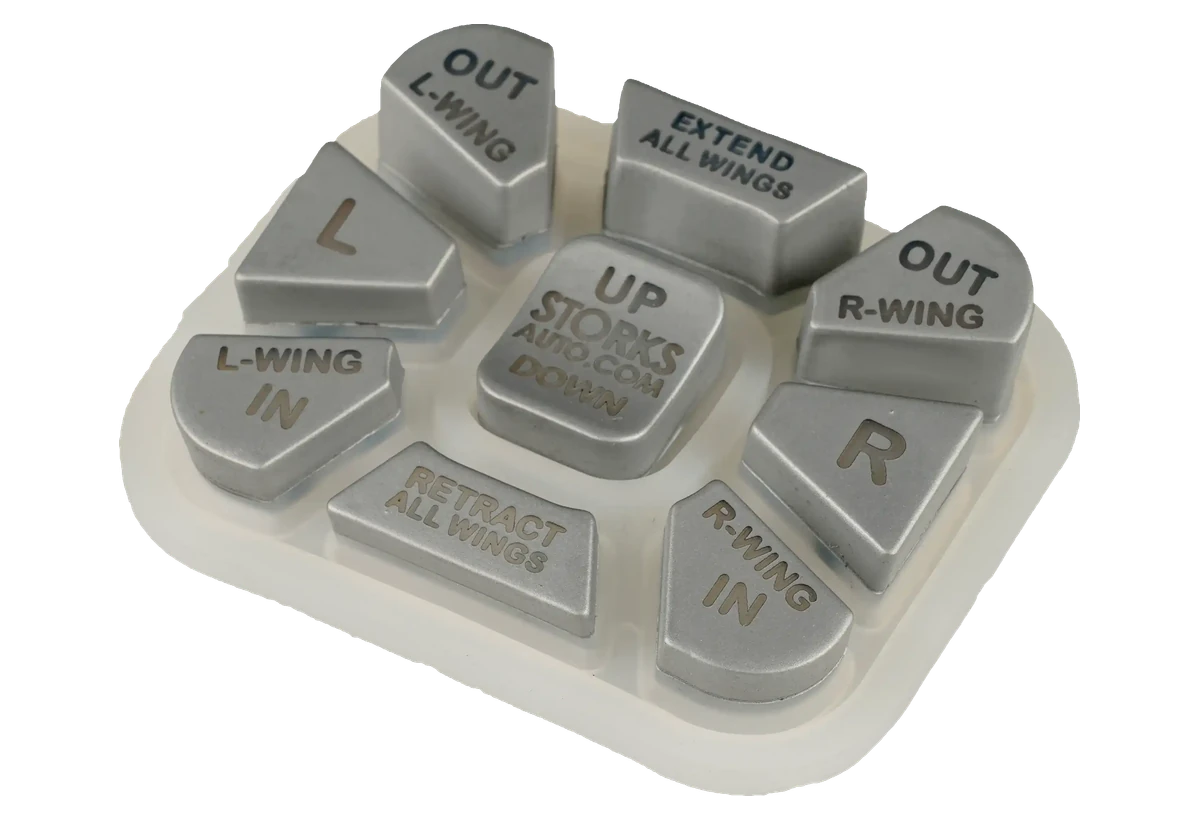
Daylight contrast, surface color, gloss, texture, and legend readability can conflict with night illumination. The approved construction must satisfy both states without relying on a photograph taken under an undefined condition.
Separate powered and unpowered requirements, ambient conditions, viewing angles, colors, and critical symbols.
Align base silicone, key geometry, coating, legend, LED package, PCB, distance, diffusion, and barriers.
Lock vector legends, locations, line widths, LED coordinates, drive condition, spacer, and enclosure partitions.
Check powered and unpowered appearance, key feel, light leakage, temperature, cleaning, fit, and variation.
Lock material, coating, laser or print, LED, PCB, fixture, inspection condition, retained sample, and change triggers.
Review LED distance, output, angle, molded thickness, diffuser, local geometry, and powered inspection condition.
Check legend opening, base transmission, coating residue, LED position, circuit height, and viewing angle.
Review spacer color, barriers, housing partitions, edge paths, key gaps, and LED output.
Review wear zone, coating adhesion, cleaner, abrasion method, key geometry, and protective stack.
Seat, console, steering, remote, and specialty interfaces requiring named day and night output.
Low-light controls whose legends, cleaning, coating, PCB, and installed evidence can be reviewed together.
Raised illuminated keys for field equipment, test systems, machinery, and control stations.
Controls reviewed for light output, moisture paths, enclosure barriers, UV, and service conditions.
Night-use PIN pads, remotes, alarm panels, and controllers with controlled cross-lighting.
Molded illuminated controls combining color, symbols, status, tactile location, and PCB integration.
An optical review needs the intended output and the physical path that creates it. Early files can still reveal whether the LED and legend can align.
It is a molded silicone keypad whose selected legends, windows, outlines, or key areas receive controlled light from LEDs or another source through a released material, surface, circuit, and enclosure path.
Use the complete optical path: material opacity, coating, spacer color, molded ribs, housing partitions, local barriers, LED position, key gaps, and edge geometry. The correct combination is proven on the installed sample.
No. Laser-opened legends are common, but molded windows, printed translucent areas, inserts, full-key illumination, or another project route may fit. Choose the method after the required powered and unpowered output is defined.
Yes, when the assembly scope defines the circuit, LED package and drive, connector, spacer, carrier, enclosure interface, optical test, packaging, and change control.
Approve powered and unpowered appearance, legend shape, color, uniformity, hot spots, cross-lighting, edge glow, key feel, fit, cleaning response, and the exact viewing and electrical condition.
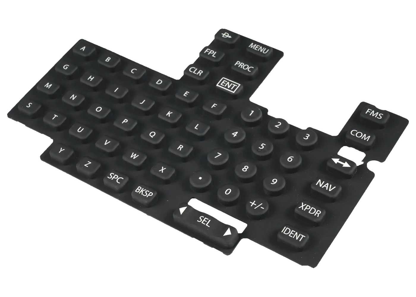
Review coating and opened-legend control when the symbol surface is the critical risk.
Review Resource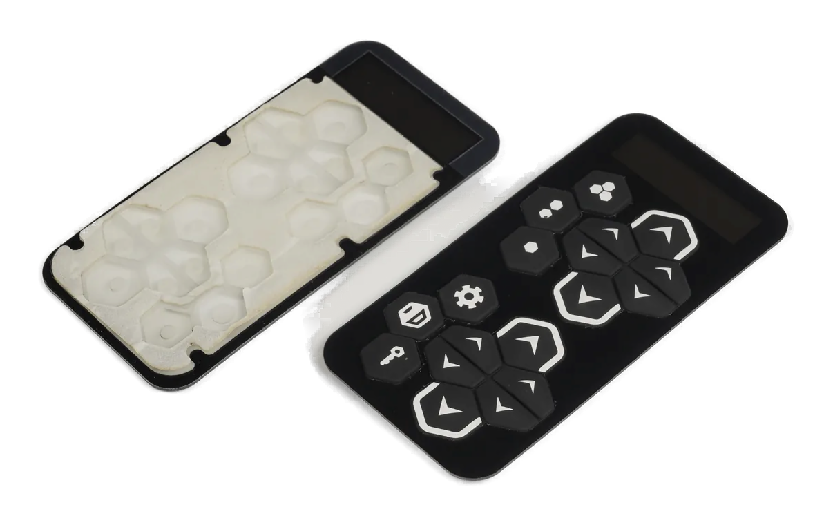
Extend responsibility through the PCB, LEDs, connector, carrier, and final optical test.
Review Resource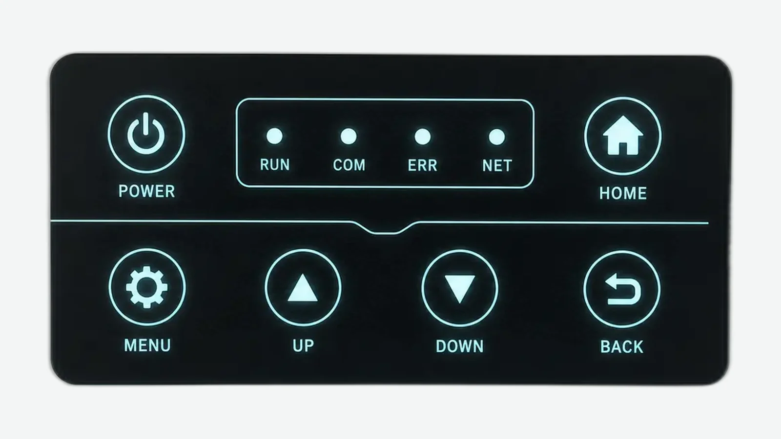
Compare LED, window, diffusion, light leakage, and viewing decisions across interface types.
Review ResourceJASPER can review the base material, coating, legend, LED, PCB, light control, key geometry, installed sample, and production inspection as one backlit silicone keypad.
Share the project basics. JASPER will review the stack, materials, connector, quantity, and production risks.