
Membrane switch backlighting is an optical path decision inside an electrical and mechanical stack. For most OEM panels the practical shortlist is discrete LED, light guide film membrane switch constructions fed by edge or side LEDs, and electroluminescent membrane switch panels. Choose by lighting task, ambient viewing, stack height, power and drive method, color coding, lifetime class, masking, and the sample method used to approve off and on states—not by a single “brightest” label.
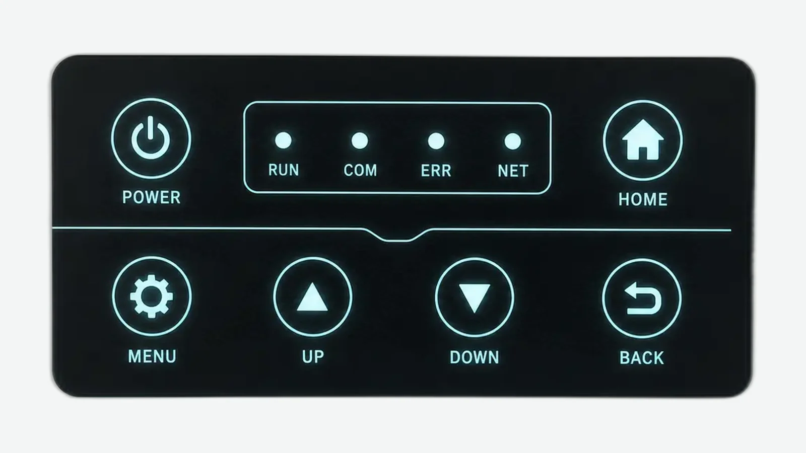
A clean legend file can still hide an open lighting architecture. One supplier may quote a single 0603 status LED on a polyester (PET) circuit, another may assume a full light-guide field under a polycarbonate overlay, and the electronics team may already have frozen a 3.3 V rail that cannot drive an EL inverter. This guide is for OEM mechanical, electronics, and industrial-design engineers who must select membrane switch backlighting before artwork, spacer, and circuit tooling freeze in 2026 programs. It supports a backlit membrane switch construction review. The evaluation criteria apply to any production-intent lighting review.
1. Why membrane switch backlighting is not a late graphic finish
Membrane switch backlighting changes more than night-time readability. Source choice locks package height, silver or copper circuit real estate, flex-tail pin count, heat near pressure-sensitive adhesive (PSA), optical masks, diffusion layers, and the way First Article Inspection (FAI) must be judged. A continuity tester can prove that LEDs or carbon/silver contacts switch. It cannot prove that a dead-front icon stays hidden when off, that a multi-key field looks even, or that light stops at the edge of an embossed key on a PET or polycarbonate face.
The practical cost of waiting is mismatched quotes under one part number, samples that look different from production ink opacity, and enclosures that compress a light guide or open a leakage path the bench sample never showed. Optical approval is a sequence of visible states—unpowered face, normal ambient, powered icons, and state-to-state transitions—not a single bright photograph on a phone.
| Failure chain stage | What gets locked early | What fails later if the decision stayed open |
|---|---|---|
| Lighting task map | Which icons, keys, logos, or bars must light | Random LEDs on every legend; wasted power |
| Source architecture | Discrete LED, LED+LGF, EL, or specialist fiber | Incomparable stack heights and drive electronics |
| Artwork and mask | Translucent windows, opaque fields, dead-front ink | Ghost icons, pinholes, washed-out color |
| Circuit and power | Polarity, current, dimming, driver/inverter, pin budget | Brown-outs, noise, wrong connector map |
| Stack and enclosure | Diffuser, reflector, air gap, mounting pressure | Hot spots, edge glow, crushed guide film |
| Sample method | Off / ambient / lit acceptance in real hardware | Partial approvals that do not transfer to production |
| Decision closed before tooling? | Typical locked assets | Safe to release screens / dies? |
|---|---|---|
| Yes — task, architecture, mask, power, and approval method Closed | Overlay print, spacer, circuit, optical layers | Yes, against a named revision |
| Partial — source named but mask or enclosure open | Artwork may look final | No — hold multi-tool release |
| No — “add backlight later” only | Front PDF only | No — RFQ will invent constructions |
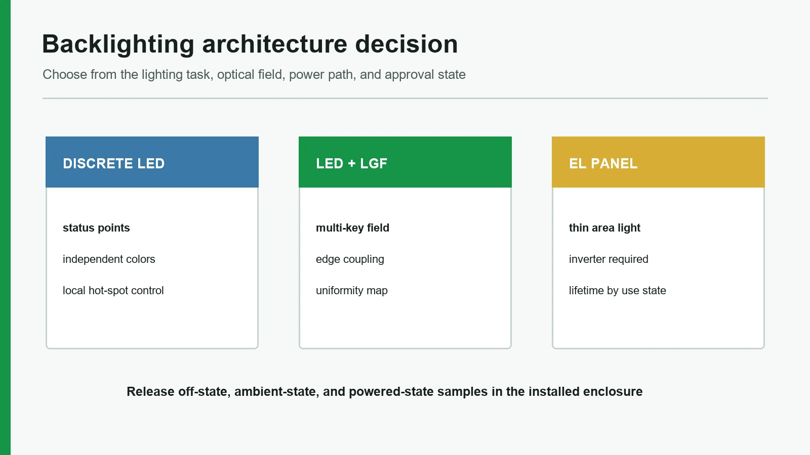
2. Nine membrane switch backlighting decisions to close before tooling
Treat each item below as a release criterion. For every criterion, a is evidence the package can proceed; a is a reason to hold tooling even if the front graphic looks finished.
2.1 Define the lighting task before naming a lamp
Not every lit feature is the same job. A single fault indicator, a row of mode icons, a full keypad field, a brand logo, and a perimeter light bar need different source density, diffusion, and isolation. Write the task first: what must be found in the dark, what must stay hidden when off, and what must never light neighboring graphics.
A zone map lists each lit feature, required on/off appearance, priority under low light, and whether the symbol is status-only or operator input.
The RFQ says “full backlighting” with no list of icons, no off-state rule, and no ambient condition.
2.2 Match brightness and viewing to the real ambient
Brightness is not a free adjective. Cabin night lighting, a factory aisle under high-bay LEDs, a laboratory hood, and outdoor shade produce different needs. Viewing distance and angle matter as much as source intensity. A status LED that looks correct on a bench may wash out at an oblique operator stance or disappear in high ambient glare on a marine or industrial console.
Ambient classes, operator position, minimum readable state, and any dimming levels are written into the sample plan.
Acceptance language is only “make it brighter” with no ambient, distance, or angle.
2.3 Choose discrete LED when the job is point light
A LED membrane switch construction places semiconductor emitters—PN-junction light sources—under selected windows. Red, green, blue, amber, white, and RGB packages suit status points, warnings, compact symbols, and small illuminated zones where independent color or on/off control is the priority. Package height (for example 0603 or 0805 class parts when the stack allows), forward voltage class, polarity, resistor or constant-current strategy, and aperture size must be locked with the circuit layer.
Industry planning ranges for small indicator LEDs commonly sit near 2.0–3.5 V forward voltage and 5–20 mA per die, with luminous intensity spanning roughly 200–2,000 mcd depending on color, lens, and bin (verify against the selected package datasheet). Extended industrial temperature grades are often quoted around −40 °C to +85 °C. Rated lifetime figures of 50,000–100,000 h appear widely in supplier literature at stated current and temperature; treat those hours as datasheet-class, not a free panel guarantee after ink, heat, and duty cycle are applied.
Discrete LEDs are the wrong default when a large multi-key field must look continuous and even without a light-management film. Hot spots and source silhouette appear when the window is too small, the diffuser is missing, or the LED sits too close to the graphic under a hard-coated overlay.
Each LED zone has package family, color intent, electrical limits (Vf/If class), window geometry, and a note on whether diffusion or a light pipe is required.
“Add LEDs under every key” with no height budget, no polarity map, and no optical isolation plan.
2.4 Use light guide film when area uniformity is the job
A light guide film membrane switch construction couples edge or side-firing LEDs into a thin polymer film that extracts light across keys or legends by total internal reflection and engineered extraction features. LGF is an optical distribution method, not a separate light-emitting physics family like electroluminescence. Extraction dots or patterns, edge coupling, white reflector, diffuser sheet, and optical boundaries control whether the field looks even or shows bright edges and dark centers.
LGF is usually the wrong choice for a single tiny status window that a discrete LED can serve with fewer layers. It is also wrong if the enclosure will press unevenly on the film or leave uncontrolled air gaps that change extraction from unit to unit.
Edge-LED count and placement, guide outline, extraction intent, reflector/diffuser stack, and keep-out zones around emboss or adhesive openings are drawn.
“Use LGF for premium look” with no edge coupling detail and no plan for leakage at cut edges.
2.5 Reserve electroluminescent panels for thin soft area light
An electroluminescent membrane switch panel uses a phosphor system that emits light under an electric field (electroluminescence). Practical EL lamps are commonly built as thin area sources and are often AC-driven, which means the product must accept driver or inverter electronics, wiring separation from sensitive signals, and a brightness class that softens rather than punches through high ambient daylight. Industry design notes frequently place EL inverter drive in the order of about 80–120 V AC (panel- and driver-specific—confirm on the selected EL + inverter pair). Panel thickness is often marketed in the sub-millimeter class, with some constructions advertised near ~0.2 mm active film before adhesives and overlay. Greenish EL hues are often selected because they align well with human visual sensitivity for a given electrical input; that is a lamp-physics tendency, not a mandatory product color.
Brightness decay is the planning constraint most buyers under-specify. Industry HMI guides commonly cite EL half-brightness life on the order of a few thousand hours—often summarized as about 3,000–5,000 h under continuous drive—versus LED package lives an order of magnitude longer at rated conditions. Use those figures only as a class comparison until the selected EL film, drive voltage/frequency, duty cycle, and measurement method are named. EL is not the best choice when the interface must remain highly visible in bright rooms, when only low-voltage DC rails exist and no driver path is allowed, or when continuous high luminance over long duty cycles is mandatory without accepting that decay class. For those jobs, LED or LED+LGF usually fit better.
EL area outline, driver ownership (including approximate AC class), dimming method, acoustic/EMI notes if relevant, environmental limits, and a lifetime framing based on the selected panel and drive condition—not a free-floating marketing hour number alone.
EL selected only because it is “the thinnest,” with no inverter location, no decay acceptance, and no EMC plan.
2.6 Close thickness, stack order, and mechanical interference
Lighting lives inside the same millimeters as domes, spacers, circuits, and rear adhesive. A text stack clarifies ownership even when layer order varies by construction:
Operator face
Graphic overlay (PET or PC print, windows, hard coat)
Optical mask / dead-front fields / translucent inks
Diffuser and/or light guide film (if used)
Discrete LEDs, EL panel, or specialist fiber extraction
Metal dome or poly dome / spacer / silver or FPC circuit
Reflector, ESD shield, stiffener as required
Rear acrylic PSA / gasket → enclosure wall
Flex tail exit → ZIF/FPC connector → board power and sense lines
Overall height budget, component clearance under emboss, and a note on what the enclosure may compress.
Lighting added after the stack and tail are already released.
2.7 Budget power, heat, and drive electronics with the connector map
Power is part of the optical design. Discrete LEDs need current control and polarity discipline. Multi-color or RGB zones add channel count on the flex tail. EL needs a compatible AC driver path separate from quiet analog sense lines when the product is noise-sensitive. Heat near dense LED fields can affect nearby acrylic PSA bonds and operator comfort inside sealed housings. Pin maps must carry lighting rails without starving the switch matrix or forcing an impossible flex width into a 0.5 mm-pitch ZIF footprint.
Supply voltage, estimated current by state, dimming method, driver ownership, and tail pin assignment appear in the RFQ package.
Artwork is final while power budget and connector pinout remain “not yet defined.”
2.8 Design masking, dead-front contrast, and light isolation as one system
Dead-front icons must be judged twice: unpowered concealment and powered readability. Opaque fields, translucent color, window edges, spacer openings, and enclosure walls all change isolation. Light leakage between icons, glowing emboss lines, and edge halo are sample defects even when every LED measures correct current.
Off-state appearance is specified, icon-to-icon isolation is required, and inspection includes dark-room leakage checks.
Only on-state photos are accepted; off-state ghosting is ignored.
2.9 Approve samples in the production-intent enclosure and light states
Bench photographs hide reflections, mounting pressure, and angle loss. A usable approval sequence covers the unpowered face, normal ambient readability, powered icons at agreed dimming levels, and transitions between states. Actuation force, tail fit, and connector clearance still belong in the same sample event so optical layers are not approved against a stack that later changes.
Written sample matrix with states, angles, ambient, pass/fail owners, and a golden sample retained against drawing revision.
Email approval of a single lit photo with no enclosure, no off-state, and no revision control.
3. LED, LGF, and EL at a glance
Use the table as a design-review starting point. Final performance depends on the approved drawing, artwork, electronics, and test environment—not on marketing adjectives alone.
| Decision axis | Discrete LED | LED + light guide film | Electroluminescent panel |
|---|---|---|---|
| Light pattern | Point or small zone | Distributed area across keys/legends | Soft area source |
| Uniformity focus | Window, diffuser, package position | Edge coupling, extraction, reflector | Area phosphor continuity and mask |
| Thickness impact | Package height under overlay (0603/0805 class common) | Thin LGF + edge LEDs; often thinner than dense direct-lit LED fields | Very thin active film (industry ~0.2 mm class possible); driver is external bulk |
| Power / drive | Low-voltage DC; industry ~2.0–3.5 V / 5–20 mA per LED (datasheet) | Low-voltage DC; fewer LEDs for area coverage | Inverter path; industry notes often ~80–120 V AC class (confirm pair) |
| Color flexibility | Strong per-zone options (R/G/B/W/RGB) | Strong; limited by LED set and film | More limited palette than multi-LED sets |
| Lifetime framing (industry class) | Package literature often 50k–100k h at rated If/temp | Same LED class + optical stack stability | Half-brightness often cited ~3k–5k h continuous; verify film + drive |
| Masking / dead-front | Window opacity and halo control | Edge leakage and key isolation | Area glow through thin masks |
| Best fit | Status, warnings, compact icons | Multi-key legends, bars, broad zones | Thin soft night readability when moderate brightness is enough |
| Primary sample risk | Hot spot, bump, narrow angle | Center/edge imbalance, crush sensitivity | Drive mismatch, decay, EMI/noise from driver |
| When NOT best | Large even fields without diffusion | Single tiny status only | High daylight punch or DC-only no-driver products |
Numeric rows above are industry-typical planning bands drawn from public HMI/backlighting guides and component-class literature. Replace them with the selected LED package datasheet, EL film + inverter data, and project sample measurements before release.
Fiber optic lighting remains a specialist path when the light source must sit away from the face for heat, routing, or certain electrical-isolation concepts. It is not the default fourth equal option for most commercial membrane keypads; treat it as an exception with its own fiber route, bend, and coupling review.
| Release evidence | Discrete LED | LED + LGF | EL panel |
|---|---|---|---|
| Electrical | Package, polarity, current, driver | Edge LEDs, driver, dimming | Inverter, frequency, connector |
| Optical | Window, color, leakage | Uniformity, edge leakage, masking | Area uniformity, off-state contrast |
| Installed sample | Point visibility in ambient light | Full field in the enclosure | Powered panel with inverter operating |
4. Step-by-step buyer process for membrane switch backlighting
Step 1 — Build the lighting task map
List every symbol that must light, every symbol that must stay dark when idle, and any color meaning (for example fault red versus ready green). Record ambient conditions and operator stance. If the map is empty, stop and write it before requesting quotes.
Step 2 — Set stack, power, and enclosure constraints
Capture maximum assembly thickness, available rails, connector family, heat limits, and how the panel mounts. Graphic overlays for backlit work commonly use PET in the 0.125–0.25 mm thickness class; thinner stock usually transmits more light, while heavily pigmented windows cut luminance. Enclosure ribs, windows, and gaskets belong in this step because they change optical cavities.
Step 3 — Shortlist architecture, not brand slogans
Match the task to discrete LED, LED+LGF, EL, or a documented specialist path. A LED membrane switch product page is the right next read when status indicators dominate. Area legends usually pull the review toward light guide film. Thin soft area glow pulls toward electroluminescent constructions when driver and decay class are acceptable.
Step 4 — Issue an RFQ package that suppliers can build the same way
Include the zone map, architecture preference or open options, electrical limits, stack height, artwork with translucent/opaque intent, connector and pin assumptions, environmental notes, and sample acceptance states. Ask suppliers to state assumptions explicitly when a field is open.
Step 5 — Review constructions for optical isolation and manufacturability
Compare quotes only when stack, source, mask, and drive method are named. Reject packages that solve brightness by ignoring leakage, dead-front, or enclosure pressure.
Step 6 — Run sample approval as electrical plus optical tracks
Confirm polarity and function, then walk off / ambient / lit / transition states in the production-intent housing. Keep a golden sample with the drawing revision. Quality and testing methods should record both tracks, not only continuity. Where early hardware is still soft-tooled, prototyping can produce optical pathfinders before steel is cut—provided the materials and ink systems remain production-intent.
Step 7 — Freeze tooling only after the lighting states pass
Release screens, dies, and fixtures against the revision that survived optical and electrical checks. Later “small” ink opacity changes can reopen dead-front behavior even when the circuit is unchanged.
5. Release blockers that disqualify a backlighting package
These override attractive unit pricing or a glossy render.
- No zone map — supplier invents which keys light.
- Architecture named without stack height — package and film collisions appear at first article.
- Power budget missing — pin maps and brown-out risk stay open.
- Dead-front required but only on-state photos accepted — off-state ghosts ship to the field.
- LGF claimed without edge-coupling and extraction intent — uniformity is luck.
- EL selected with no driver ownership — “thin panel” hides external electronics.
- Universal life hours quoted with no datasheet or drive condition — not a controllable requirement.
- IP rating claimed from lighting method alone — IEC 60529 rates enclosures, not a loose switch construction.
- Sample approved only on a free bench — enclosure pressure and angle loss are ignored.
- Artwork frozen before optical windows and masks are dimensioned — print tools lock the wrong openings.
6. Frequently asked questions
What are the main membrane switch backlighting options?
For most OEM membrane panels the practical set is discrete LED for point status, LED with light guide film for even multi-key or legend fields, and electroluminescent panels for thin soft area glow. Fiber optic is a specialist alternative when the source must be remote. Hybrid stacks appear when status LEDs and area legends share one interface.
Is a light guide film membrane switch better than discrete LEDs?
Only when the job is distributed uniformity across a field. LGF adds film, coupling, and isolation work. A single status window is usually cleaner with a discrete LED membrane switch construction and a controlled aperture.
When is an electroluminescent membrane switch the wrong choice?
When the panel must punch through high ambient light, when only simple low-voltage DC drive is allowed without a driver path, or when the product cannot accept EL brightness decay over life. Industry guides often place continuous-drive half-brightness life in the ~3,000–5,000 h class versus LED package literature at ~50,000–100,000 h under rated conditions—an order-of-magnitude planning gap, not a calibrated field result. Verify against the selected EL film and inverter. In those high-duty or high-ambient cases, LED or LED+LGF is usually the better architecture.
What causes hot spots on a backlit membrane keypad?
Common causes include a source too close to a small window, missing diffusion, uneven LGF extraction, reflective enclosure ribs, and translucent ink that is too clear in the center of an icon. Fix the optical path; raising current alone often worsens the silhouette.
How do you prevent light leakage between icons?
Control opaque masks, window edges, spacer openings, guide boundaries, and enclosure walls as one system. Inspect in a dark environment with adjacent icons powered separately. Electrical continuity does not prove isolation.
Can dead-front graphics work with membrane switch backlighting?
Yes, when off-state opacity and on-state transmission are designed together and approved in both states under agreed ambient light. Dead-front is a print-and-mask problem as much as a lamp problem.
What electrical details belong in a backlighting RFQ?
Supply voltage, estimated current by lighting state, dimming method, polarity, driver or inverter ownership for EL (including AC class if used), connector and pin map, and any heat or EMC constraints. For discrete LEDs, state the target Vf/If class—industry indicators often land near 2.0–3.5 V and 5–20 mA per die until a package is chosen. Without those fields, optical samples cannot be reproduced.
How should an OEM approve a backlit membrane switch sample?
Install the production-intent stack in the real enclosure, then review unpowered appearance, normal ambient readability, powered icons at agreed levels, transitions, isolation, actuation, and connector fit. Retain a golden sample against the drawing revision.
Does backlighting determine an IP rating?
No. IEC 60529 classifies protection provided by enclosures for electrical equipment. Sealing depends on the assembled enclosure, gaskets, and test article—not on whether the panel uses LED, LGF, or EL. Environmental stress methods, when required, should be selected from a defined plan (for example methods in the IEC 60068 family) against the finished equipment—not invented as a free lighting label.
7. What to do next
Close the nine decisions above, then send a package that names the lit icons, color intent, and power budget with the current artwork and enclosure constraints. That single input set prevents most fake precision in early quotations.
For a worked optical review of status indicators, dead-front icons, and lit/unlit inspection, see the anonymous backlit panel with LED indicators case. For construction ownership beyond lighting, continue with the membrane switch design guide or a circuit design pass when pin maps are still open.
Send the drawing with lit zones, color, and electrical limits for an engineering lighting review, or start from the backlit membrane switches product page if the architecture is already chosen.
Technical References
- Source: Covestro Makrofol and Bayfol Film Selector Guide for light-management films. Accessed 2026.
- Source: 3M Membrane Switch White Spacer 7966MWS technical data. Accessed 2026.
- Source: Selected LED package electrical datasheet for the released circuit. Accessed 2026.
- Source: IEC 62471 photobiological safety for lamps and lamp systems. Accessed 2026.
- Source: CIE 1931 colorimetric observer framework. Accessed 2026.
- Source: IEC 60068-2-14 temperature change testing. Accessed 2026.
- Source: IEC 60068-2-6 sinusoidal vibration testing. Accessed 2026.
- Source: Bivar side-view surface-mount LED technical data. Accessed 2026.
- Source: ROHM side-view surface-mount LED technical data. Accessed 2026.
- Source: 3M light-management film technical resources. Accessed 2026.
- Source: Covestro Makrofol LM light-diffuser film data. Accessed 2026.
Select the backlight before artwork release
Send the lit-zone map, ambient viewing condition, power rail, color targets, stack limit, and powered sample acceptance states.