
Substrate
PET or polycarbonate film, thickness range, flex zones, surface texture, and protective liner.
Turn approved artwork into a production front panel with the film, printing, windows, key features, cut geometry, and adhesive matched to the real enclosure.
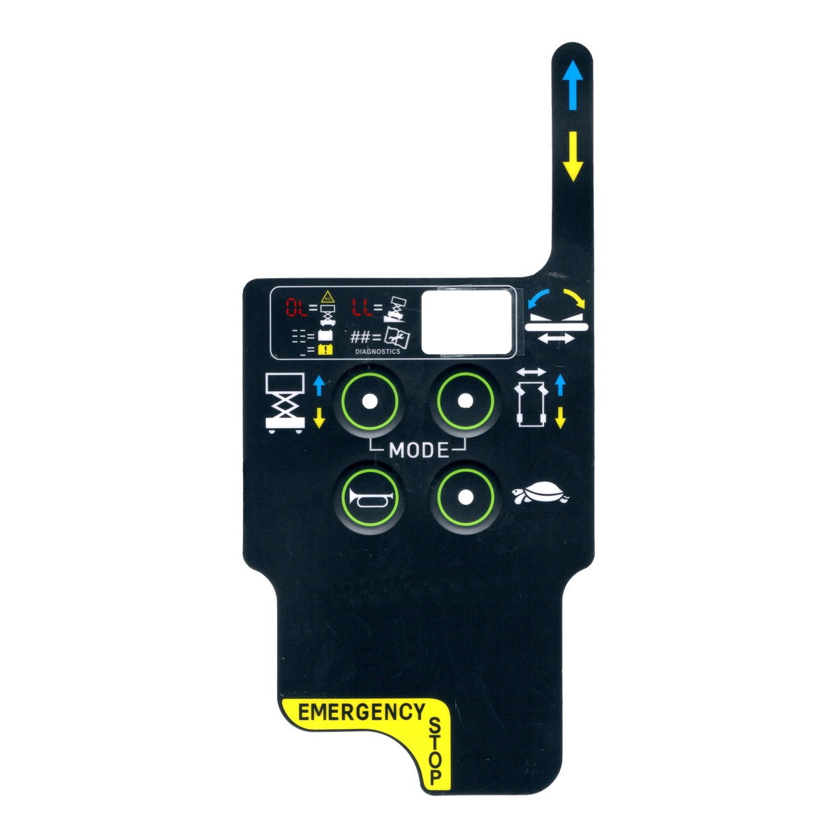
A custom graphic overlay is a printed and die-cut front surface made from customer artwork. It carries legends, colors, windows, icons, branding, and key-location cues while protecting the enclosure and components below.
The overlay can ship as a standalone adhesive-backed panel or become the top layer of a membrane switch or HMI assembly. It does not create electrical switching by itself, so the visible surface and the circuit beneath it should be specified as separate but coordinated parts.
The drawing should make each decision visible. Leaving one of these areas undefined usually moves the risk into sampling.
PET or polycarbonate film, thickness range, flex zones, surface texture, and protective liner.
Spot colors, process color, reverse print, opaque backgrounds, transparent inks, and color approval method.
Clear, tinted, anti-glare, dead-front, indicator, display, or shielded window requirements.
Flat areas, rim or pillow embossing, selective texture, dome registration, and tactile clearance.
Full or selective coverage, panel material, surface energy, texture, recess, edge land, and liner split.
Cleaning chemicals, UV, temperature, moisture, abrasion, glove use, and required project testing.
PET and polycarbonate are both useful overlay materials. The right choice depends on the complete exposure and feature set, not a generic preference.
| Decision | PET Direction | Polycarbonate Direction |
|---|---|---|
| Typical strength | Flex endurance and broad chemical-resistance options | Print appearance, formed detail, and impact-oriented options |
| Key areas | Useful where repeated flexing or key actuation is expected | Useful where the part is mostly static or formed detail dominates |
| Surface options | Matte, gloss, textured, and hard-coated grades | Gloss, matte, textured, and specialty surface grades |
| Review focus | Cleaner, UV, flex radius, crack initiation, and coating compatibility | Cleaner, stress cracking, flex zones, impact, and coating compatibility |
| Approval method | Test the selected grade with the real ink, finish, adhesive, and cleaning process | Test the selected grade with the real ink, finish, adhesive, and cleaning process |
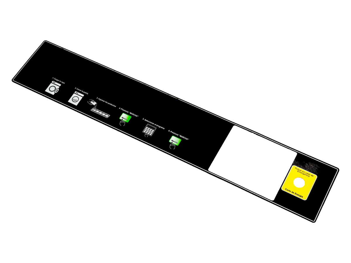
Display openings, LED icons, printed legends, emboss geometry, and the enclosure behind them share the same tolerance chain. Review the front artwork over the actual display, dome, bezel, and light source before the die line is released.
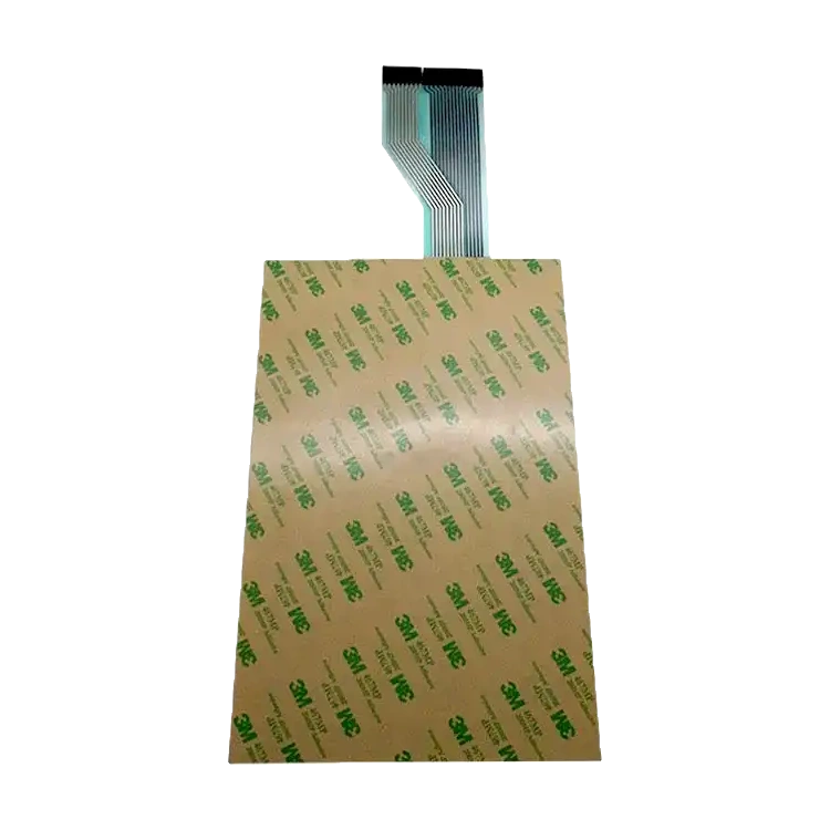
The bond is controlled by the substrate, texture, flatness, recess depth, edge land, contamination, temperature, and installation pressure. Specify the panel and assembly process before selecting the final adhesive construction.
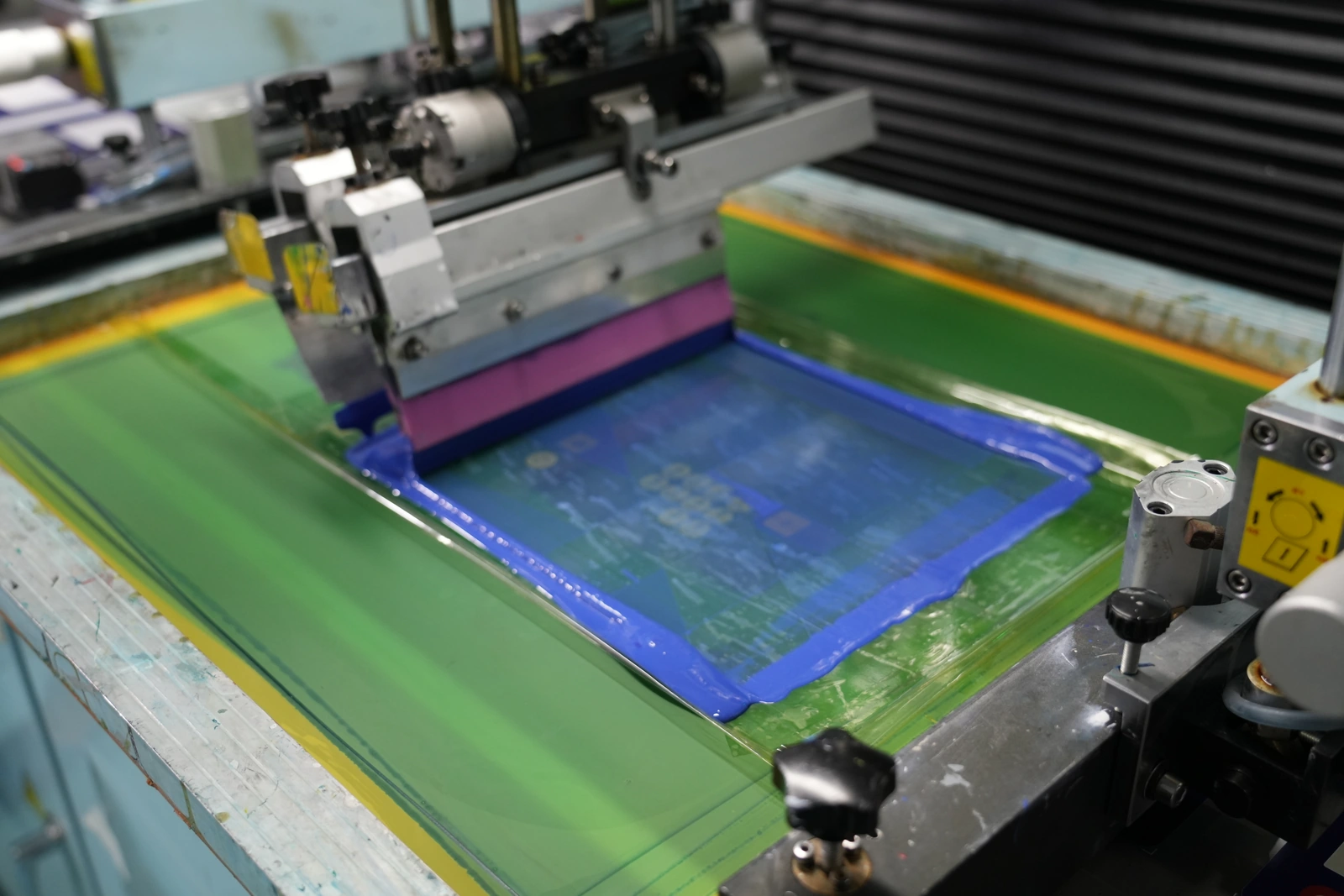
The approved artwork becomes physical screens, ink layers, windows, coatings, laminations, and die-cut geometry. Production review should define how color, opacity, registration, surface defects, dimensions, and adhesive preparation are checked.
The visual proof can look correct while the finished outline, windows, or holes still conflict with the enclosure.
Screen appearance does not prove the printed color, opacity, texture, or appearance under factory and field lighting.
Clear, tinted, diffused, anti-glare, and dead-front windows behave differently over real displays and indicators.
A strong adhesive name does not correct low surface energy, texture, contamination, narrow lands, or an uneven mounting plane.
Emboss radii and dome positions can push legends, windows, and cut geometry into unstable areas.
Fit, bond, glare, display alignment, and operator readability can only be approved in the final assembly condition.
Function legends, display windows, status icons, and durable operator guidance.
Wipe-clean surfaces, controlled labels, windows, and consistent user instructions.
Brand graphics, flat controls, dead-front indicators, and high-volume assembly.
Dense legends, display openings, key grouping, and revision-controlled model identification.
Public-use instructions, high-contrast graphics, abrasion-resistant surfaces, and service labels.
Glove-readable graphics, backlit icons, shaped panels, and exposure-driven material selection.
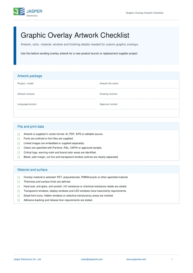
Use the checklist to organize the vector file, colors, cut line, windows, emboss areas, surface finish, adhesive coverage, and revision information.
Yes. It can be supplied as a standalone printed and die-cut front panel or label, or it can become the top layer of a membrane switch or HMI assembly.
Vector AI, press-ready PDF, EPS, DXF, or a dimensioned drawing are useful. Keep the cut line, windows, print colors, emboss areas, adhesive keep-outs, and revision information clearly separated.
Approve color under the intended lighting, print registration, window clarity, surface finish, key location, cut geometry, adhesive fit, liner removal, and mounting behavior on the real panel.
Selection depends on the enclosure material, surface energy, texture, flatness, temperature, chemicals, edge geometry, and installation process. A named adhesive should still be validated on the real substrate.
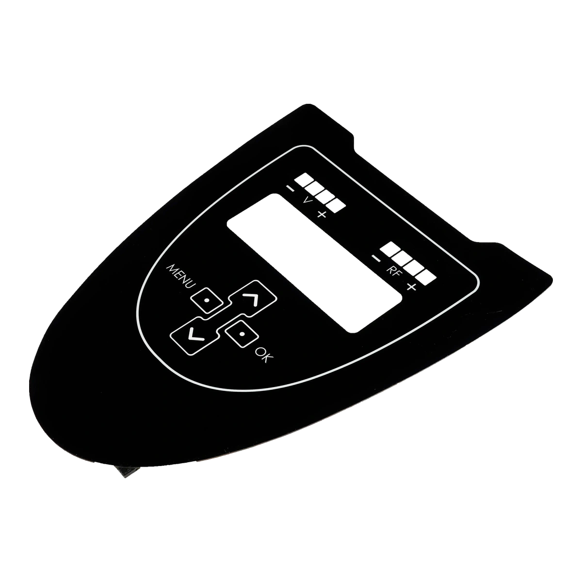
Compare rigid PMMA front panels and shaped clear cover lenses.
Read Resource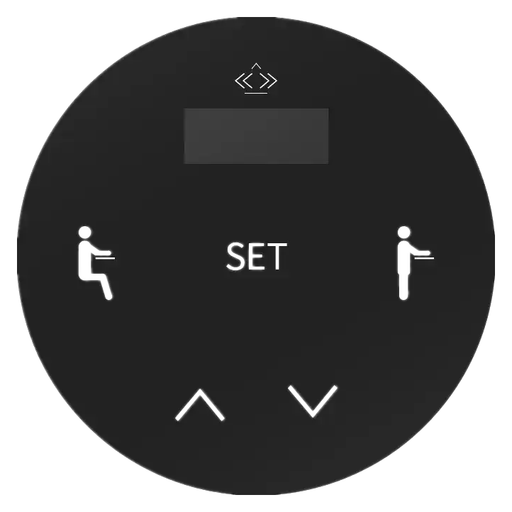
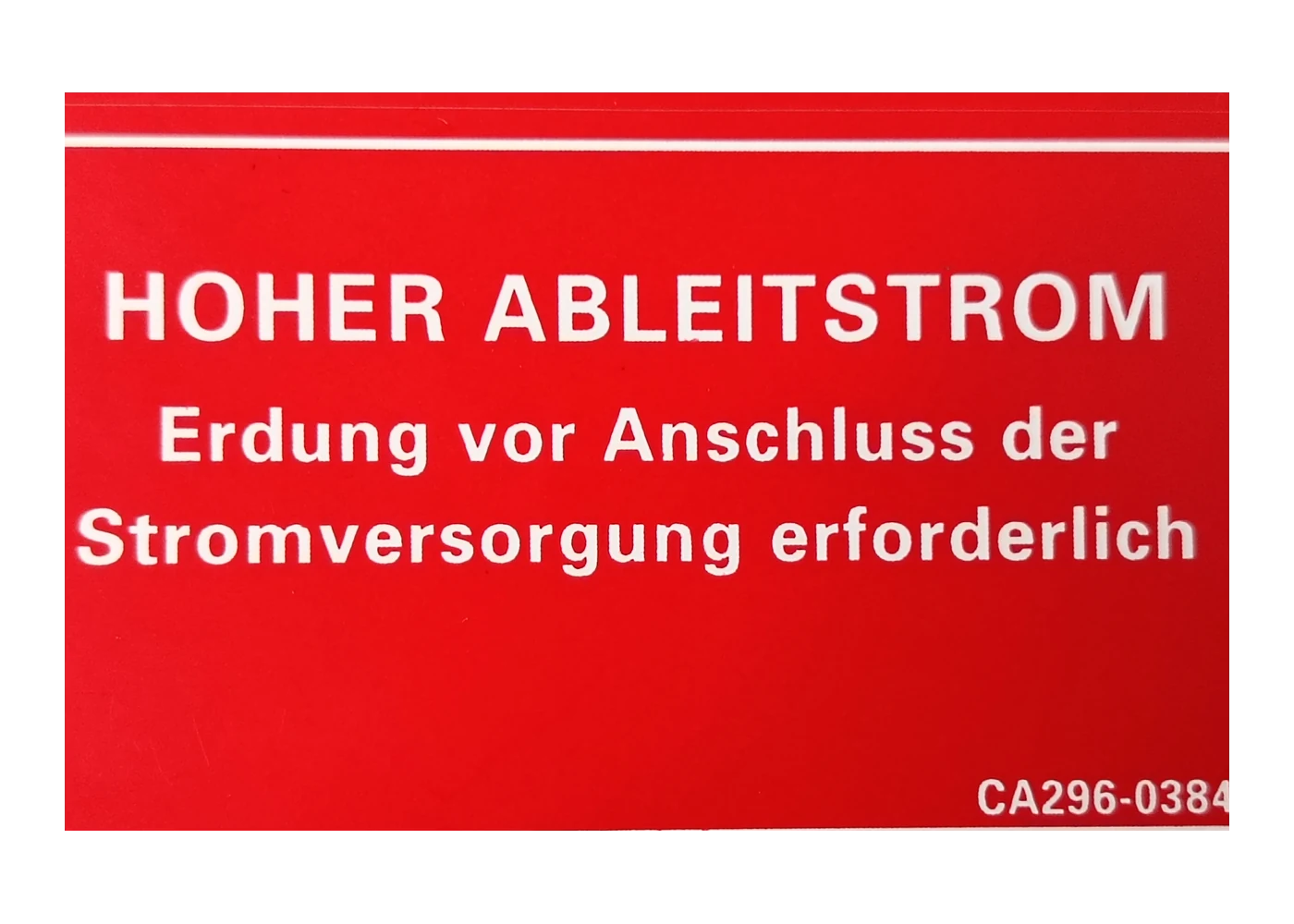
Plan durable printed identification, warnings, ratings, and variable information.
Read ResourceShare the artwork, enclosure surface, windows, environment, quantity, and fixed requirements so the front surface can be reviewed as one system.
Share the project basics. JASPER will review the stack, materials, connector, quantity, and production risks.