
Drawing and DFM review
We check dimensions, tolerances, cutouts, key spacing, bend areas, tail exits, mounting features, and the points where the interface meets the enclosure.
Send an early drawing, CAD file, or marked-up concept. Our team reviews the interface as a working system so stack, circuit, sealing, connector, and assembly risks can be discussed before sample tooling.
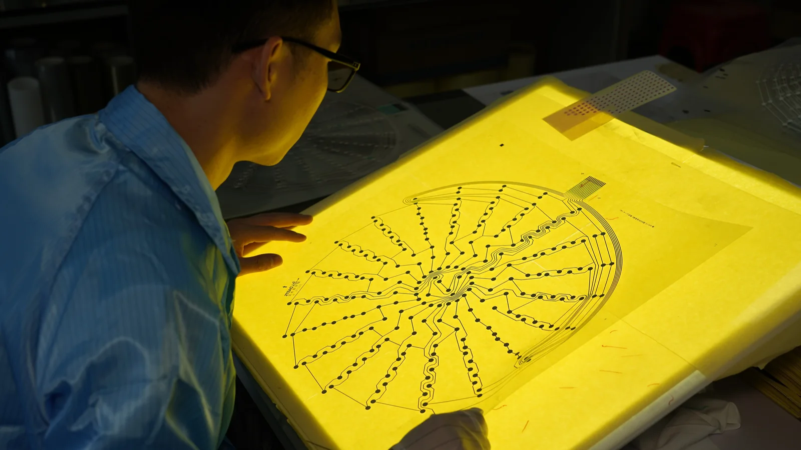
The review is built around the decisions that affect manufacturability, fit, feel, and field reliability. The exact depth depends on the product family and the information available.
We check dimensions, tolerances, cutouts, key spacing, bend areas, tail exits, mounting features, and the points where the interface meets the enclosure.
Overlay film, spacer, circuit substrate, adhesive, dome, backer, lens, and gasket choices are reviewed against use conditions and assembly needs.
We review contact layout, routing space, tail length, bend direction, pinout, connector style, strain relief, and the transition into the customer assembly.
Key geometry, dome selection, embossing, dead-front graphics, LED windows, and light-guide concepts are considered as one operator experience.
Exposure to moisture, dust, cleaners, temperature, UV, abrasion, and mounting surfaces is used to identify sealing and material risks.
We clarify how the interface will be bonded, connected, supported, sampled, inspected, and approved before it moves into repeat production.
A membrane switch or HMI can look correct on a drawing and still fail at the enclosure, connector, adhesive, or test stage. These three views keep the review tied to the physical product.
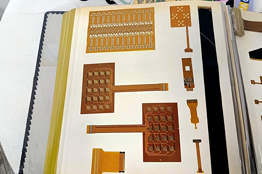
Graphics, windows, tactile areas, layer thickness, adhesive openings, and tail geometry must work together.
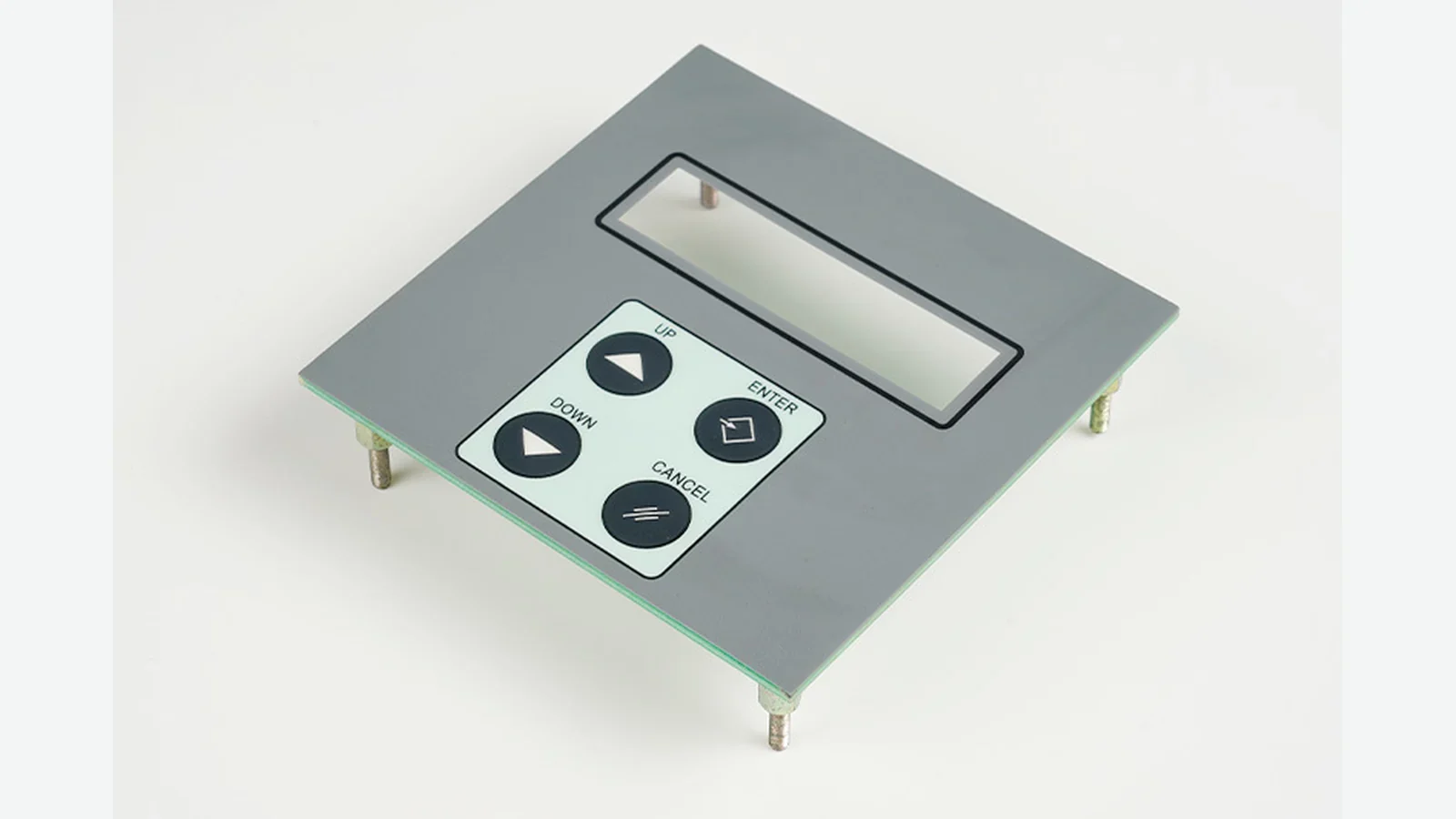
Visible features are checked against the mechanical opening, display area, mounting surface, and assembly sequence.

Pinout, continuity, sample checks, acceptance notes, and released files need a clear path into manufacturing.
A final drawing is not required. A clear early package is often more valuable because important choices can still be changed before tooling.
PDF, AI, DXF, DWG, STEP, Gerber, or a dimensioned sketch can all provide a starting point. Add notes where the design is still open.
Outline dimensions, key and window locations, enclosure opening, mounting surface, available thickness, tail exit, and bend limits.
Indoor or outdoor use, expected cleaning, moisture or dust exposure, temperature range, UV, glove use, and operator interaction.
Sample quantity, estimated production volume, target milestone, required documents, and any standards or material restrictions that apply.
The output is practical project direction, not a generic design report. We focus on the decisions needed to quote, sample, and release the product with fewer avoidable revisions.
A proposed stack or construction direction based on the drawing, application, and assembly constraints.
A concise list of missing inputs, conflicting requirements, and design points that need a customer decision.
Project-specific options for films, adhesives, domes, connectors, gaskets, windows, and backlighting components.
The functional, visual, dimensional, and assembly points that should be checked during sample approval.
A cleaner basis for quotation, tooling discussion, sample planning, and production handoff.
The review follows the maturity of the project. It can start with a rough concept and become more detailed as the construction is confirmed.
Send the drawing, application notes, quantity, and known mechanical or electrical constraints.
We identify gaps, explain practical tradeoffs, and confirm the construction direction before sampling.
Samples are reviewed against the agreed drawing, appearance, fit, electrical function, and project-specific checks.
Approved revisions, change notes, and production references are kept aligned for the manufacturing handoff.
A successful sample is only useful when the approved construction is traceable. Part number, drawing revision, artwork, circuit data, connector details, and change notes should move together.
The same review method is adapted to each product family rather than forcing every project into a membrane-switch-only checklist.
Yes. Early review is often the best time to discuss tail exit, connector, material, adhesive, sealing, and enclosure constraints because the design is still flexible.
PDF, AI, DXF, DWG, STEP, Gerber, or a clear dimensioned sketch can work. Include notes for quantity, connector, environment, materials, and any open questions.
We can propose project-specific directions based on the application and available information. Final selection remains tied to customer requirements, validation needs, and approved samples.
No. We can identify which items are firm, which are assumptions, and which decisions must be resolved before an accurate sample or production quotation.
Changes should be documented against the released revision. If they affect fit, stack, circuit, materials, sealing, or appearance, the affected checks should be repeated before production release.
A short engineering review can expose the decisions that drive tooling, sample quality, assembly fit, and production readiness. Send what you have, including marked-up or incomplete files.
Share the project basics. JASPER will review the stack, materials, connector, quantity, and production risks.