Dongguan, Guangdong 523927, China[email protected]+86 136 3262 5290
Home / Products / Medical Electrode Pads / Custom TENS, EMS, and NMES Electrode Pads
CUSTOM PRINTED PAD CONSTRUCTIONS FOR OEM STIMULATION DEVICES

Custom TENS, EMS, and NMES Electrode Pads

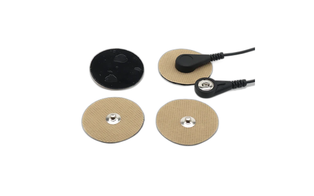
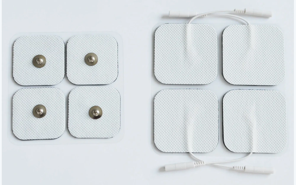
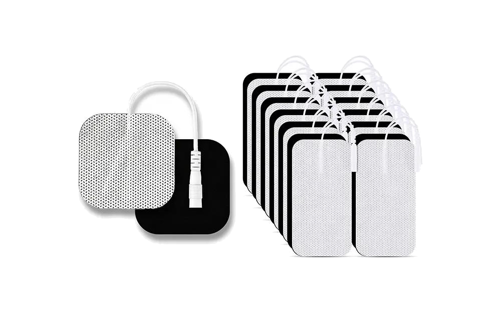
Pair of custom printed TENS EMS and NMES electrode pad constructions

JASPER manufactures custom printed conductive pad geometries and converted assemblies for TENS, EMS, and NMES device programs. The released scope may include conductive areas, printed traces, lead or connector attachment, backing, project-specified adhesive or hydrogel zones, reinforcement, liner, labels, die cutting, packaging, and agreed inspection. Waveforms, current limits, placement, treatment logic, reuse policy, patient safety, and finished-device validation remain with the OEM.

Pair of custom printed TENS EMS and NMES electrode pad constructions
Conductive area releasedpad outline, active geometry, trace transition, edge margin, and lead interface
Converted materials controlledbacking, adhesive or hydrogel zones, liner, reinforcement, die cut, label, and package
OEM stimulation validationwaveform, current, thermal behavior, placement, treatment, reuse, safety, and compliance

The Manufactured Pad Must Be Separated from the Stimulation Protocol

TENS, EMS, and NMES labels describe device uses, not a complete pad specification. Manufacturing needs the conductive geometry, material stack, lead or connector interface, edge construction, converted outline, package, and measurable acceptance criteria.

JASPER can build and inspect the released physical and electrical construction. The OEM defines and validates waveform, current, duty cycle, temperature, placement, treatment protocol, reuse or single-use policy, warnings, patient use, and regulatory pathway.

Custom TENS, EMS, and NMES Electrode Pads fit when:

  • the OEM needs a custom pad shape, conductive area, edge margin, lead, snap, tab, or connector interface
  • printed traces and converted material zones must stay registered as one construction
  • project-specific backing, adhesive or hydrogel, reinforcement, liner, labels, and packaging can be released
  • the OEM owns stimulation settings, placement, treatment, thermal, reuse, safety, clinical, and regulatory validation

Six Controls for a Custom Stimulation Electrode Pad

The drawing should define the supplied pad without embedding assumptions about the therapy or device output.

01

Conductive geometry

Release control

Release active area, printed pattern, edge margin, current-entry region, trace transition, orientation, and tolerance.

If it is missing

A pad with the correct outside shape has a different conductive area than the OEM evaluated.

02

Lead or connector interface

Release control

Define wire, snap, tab, printed tail, connector, attachment, reinforcement, polarity marking, mating part, and pull method.

If it is missing

The interface adds stiffness, shifts the conductor, or does not match the OEM cable.

03

Backing and edge construction

Release control

Control backing, foam or nonwoven, reinforcement, edge seal or margin, adhesive-free zones, and handling tabs.

If it is missing

The converted edge or lead transition differs from the released mechanical construction.

04

Adhesive or hydrogel zones

Release control

Map exact project-specified material, active coverage, overlap, thickness, liner, and non-contact areas.

If it is missing

The active area is covered, exposed, or changed by uncontrolled material overlap.

05

Electrical inspection boundary

Release control

Define continuity, resistance method, isolation, attachment, conditioning, fixture, sampling, and records.

If it is missing

A manufacturing result is interpreted as proof of current distribution, temperature, or patient safety.

06

Package and change control

Release control

Release liner, label, count, pouch or tray, storage and shipment conditions, lot traceability, substitutions, and notification.

If it is missing

Material or package changes enter production without OEM evaluation.

Release the Pad Geometry, Materials, and OEM-Owned Use Boundary

Project values must come from the stimulation-device design and validation plan.

BoundaryOptions to ReviewRelease Question
Conductive patternSolid area, segmented print, custom shape, edge margin, trace transition, contact opening, orientation, and toleranceWhich geometry was evaluated by the OEM device program?
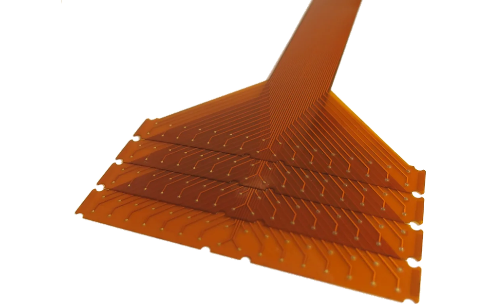
Printed circuitInk, substrate, trace, dielectric, conductor transition, continuity, resistance method, isolation, and conditioningWhat manufacturing electrical criteria apply?
Lead connectionWire, snap, tab, printed tail, connector, attachment, reinforcement, bend zone, polarity mark, and mating partWhat physical and electrical state reaches the OEM?
Converted stackBacking, foam or nonwoven, adhesive or hydrogel zones, edge construction, liner, label, and handling tabWhich exact materials and zones are supplied?
InspectionDimensions, registration, appearance, continuity, resistance, attachment, liner coverage, label, count, and traceabilityWhich records prove the supplied pad construction?
OEM validationWaveform, current, duty cycle, thermal behavior, placement, wear, reuse, treatment, warnings, safety, and complianceWhich outcomes remain outside JASPER's manufacturing evidence?
Exploded custom stimulation electrode pad layer stack
CONDUCTIVE AND EDGE ZONES

Dimension the Active Pattern Separately from the Outside Die Cut

The pad outline, conductive print, adhesive or hydrogel coverage, edge margin, lead entry, reinforcement, and liner can each have a different boundary. A single silhouette does not release the functional stack.

  • provide separate geometry for print, dielectric, material zones, and die cut
  • control the conductor-to-lead transition and local reinforcement
  • state electrical inspection without converting it into a treatment claim
  • approve the production liner and package with the sample
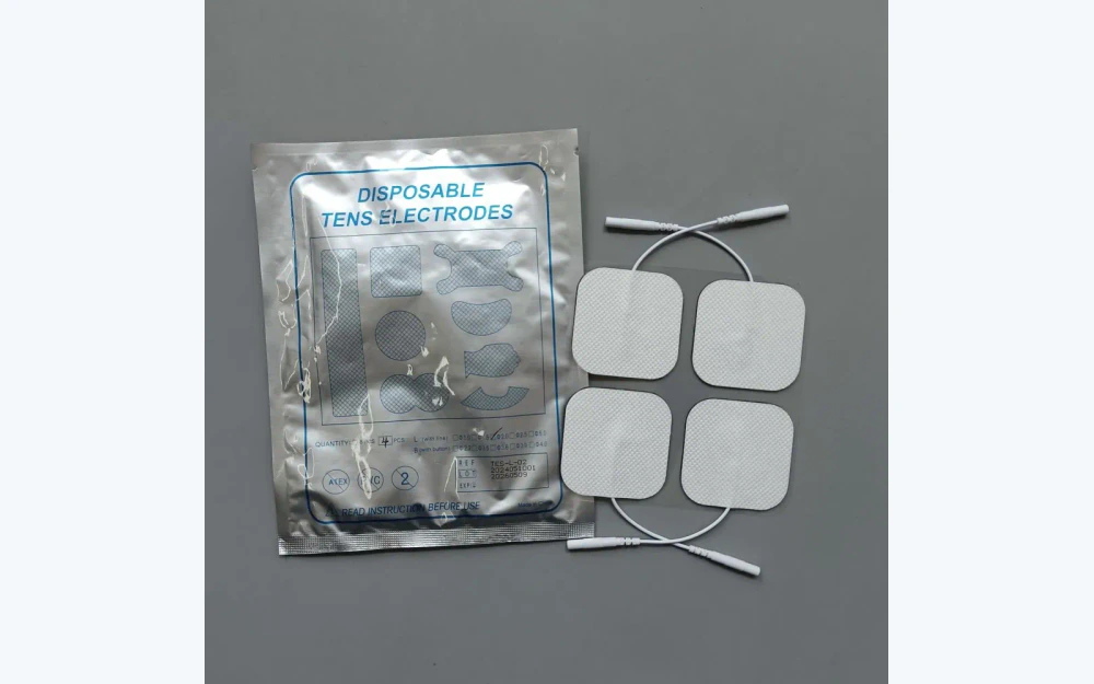
Custom stimulation electrode pads arranged for inspection and packaging
PACKAGING CONTROL

Protect the Released Material and Interface State after Inspection

The package should preserve the liner, conductive and adhesive zones, lead or connector, label, count, and orientation specified by the OEM. Storage, shipment, shelf-life, and reuse conclusions require customer validation and cannot be inferred from the package alone.

  • define pack orientation and lead protection
  • retain material and package lot identity
  • separate storage instructions from validated shelf-life claims
  • name changes that require new OEM samples

Move from Printed Geometry to a Controlled OEM Handoff

01

Define the device boundary

Release pad role, interface, placement assumptions, device output boundary, and all OEM-owned use and safety validation.

02

Release conductive geometry

Close active pattern, print, trace transition, dielectric, edge margin, lead interface, and electrical checks.

03

Close converted materials

Name backing, adhesive or hydrogel zones, reinforcement, liner, labels, die cut, and approved sources.

04

Approve packaged samples

Review geometry, registration, electrical inspection, attachment, liner, handling, label, and package state.

05

Control repeat production

Lock revisions, sources, process, fixtures, records, packaging, substitutions, and OEM requalification triggers.

Separate Pad Manufacturing Variation from Device Behavior

01

Conductive area is misregistered

Compare print master, dielectric, adhesive or hydrogel zone, die-cut datum, lamination, fixture, and inspection method.

02

Lead attachment varies

Review wire or hardware source, reinforcement, attachment process, conductor transition, pull method, orientation, and package support.

03

Electrical inspection varies

Check ink and substrate lots, print thickness, cure, trace geometry, conditioning, fixture contact, and measurement method.

04

Device behavior differs from expectation

Separate manufactured geometry from waveform, current, duty cycle, placement, skin condition, temperature, treatment logic, cable, and finished-device validation.

Where Custom TENS, EMS, and NMES Pad Manufacturing Fits

01

OEM TENS device programs

Custom conductive pad constructions matched to an OEM cable and stimulation architecture.

02

EMS equipment programs

Printed pad geometries and converted layers supplied to customer-owned output and use validation.

03

NMES device development

Prototype and repeat pad builds released against an OEM electrical and treatment boundary.

04

Rehabilitation hardware

Custom shapes, lead interfaces, liners, labels, and packaging for validated equipment programs.

05

Research stimulators

Application-specific printed pads for controlled laboratory hardware and study protocols.

06

Private-label device components

OEM-released pad formats manufactured without assuming the finished device claim or approval.

RFQ PACKAGE

Send the Pad Pattern, Lead Interface, and Device Validation Boundary

A clear RFQ distinguishes what JASPER manufactures from what the stimulation-device program must prove.

  • outside outline, conductive pattern, active area, edge margin, orientation, current-entry region, and registration datum
  • conductive ink, substrate, trace transition, dielectric, continuity, resistance method, isolation, and conditioning
  • wire, snap, tab, tail, connector, attachment, reinforcement, bend zone, polarity mark, mating part, and pull acceptance
  • backing, foam or nonwoven, adhesive or hydrogel zones, liner, label, edge construction, and handling tabs
  • dimensions, registration, visual criteria, electrical inspection, attachment, liner, count, package, and traceability
  • prototype quantity, annual estimate, lot definition, storage and shipment, change control, and OEM use and safety validation plan
Send Stimulation Pad Files

Custom TENS, EMS, and NMES Electrode Pads FAQ

Can JASPER manufacture custom TENS, EMS, and NMES pad shapes?

Yes, when the conductive geometry, printed circuit, lead interface, converted materials, die cut, inspection, packaging, and OEM validation boundary are released.

Can lead wires, snaps, or connectors be assembled?

Yes, with a released part, attachment method, reinforcement, conductor transition, orientation, mating interface, pull method, inspection, and package protection.

Does JASPER validate stimulation settings or patient safety?

No. Waveform, current, duty cycle, thermal behavior, placement, treatment, reuse, warnings, patient safety, clinical outcomes, and finished-device compliance remain with the OEM.

Can project-specified hydrogel be converted with the pad?

It can be included when supplier, grade, zone geometry, overlap, liner, handling, storage, packaging, inspection, and OEM validation requirements are explicit.

What electrical checks can be included?

The project may define continuity, resistance to an agreed method, isolation, and attachment checks for the supplied construction. These do not establish current distribution, thermal behavior, treatment efficacy, or patient safety.

Related Electrode and Printed Circuit Routes

Release the printed pad pattern and the OEM-owned stimulation boundary in the same review.

JASPER can review conductive geometry, lead interface, converted materials, die cutting, electrical inspection, packaging, traceability, and change control.

Start Stimulation Pad ReviewContact Engineering