
Indicator function
Release controlName every LED state, icon, color, steady or flashing behavior, priority, controller, and failure response.
If it is missingThe part lights but communicates the wrong system state.
An LED membrane switch integrates status indication into the front interface. Component height, color, wavelength, voltage, current, polarity, resistor ownership, viewing angle, dead-front ink, aperture, light blocking, tail routing, and test method must be released together.
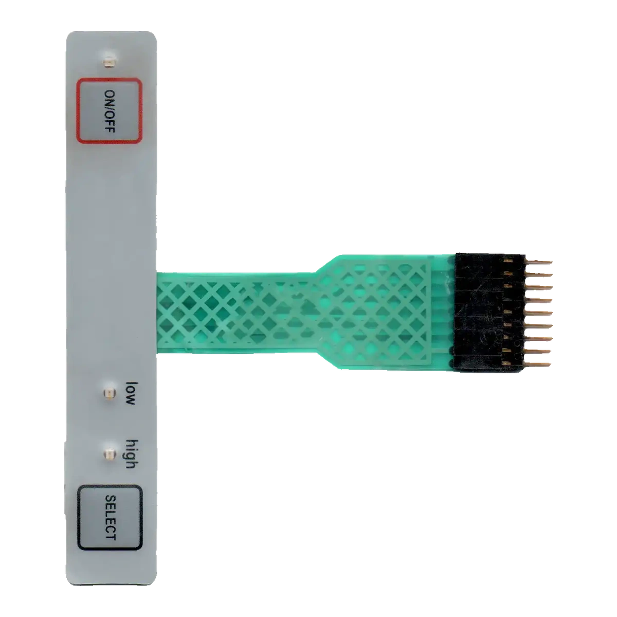
Discrete LEDs are well suited to status points, warnings, and compact illuminated icons. They are not automatically a good area-light source; broad keys or legends may need a light-guide film, diffuser, reflector, or a different backlighting architecture.
A dead-front icon has two acceptance states. When unpowered, it should be hidden or subdued without obvious pinholes. When powered, it should be readable at the specified ambient light and viewing angle without revealing neighboring icons or the LED package.
The electrical drawing must state who supplies the resistor or driver and where it sits. Supply variation, duty cycle, dimming, color bin, component height, and connector pinout can affect both appearance and reliability.
Electrical correctness and optical appearance must be released against the same LED location.
Name every LED state, icon, color, steady or flashing behavior, priority, controller, and failure response.
If it is missingThe part lights but communicates the wrong system state.
Release voltage, current, polarity, duty, dimming, resistor or driver ownership, connector, and pinout.
If it is missingBrightness or reliability changes with the customer controller or harness.
Control LED package, height, orientation, placement, soldering, circuit support, clearance, and enclosure pressure.
If it is missingThe package creates a bump, shadow, stress point, or assembly collision.
Define icon, printed opening, diffuser, color filter, distance, viewing angle, ambient light, and brightness target.
If it is missingThe indicator is visible only from one angle or looks like a hot spot.
Use opaque ink, barriers, spacer geometry, adhesive control, edge masking, and reflective surfaces intentionally.
If it is missingLight leaks into adjacent graphics, windows, or key zones.
Define state sequence, current, polarity, visual limits, dark-room and ambient checks, fixture, and records.
If it is missingContinuity passes while optical defects leave production.
Release the electrical state and visible state together.
| Decision | Options to review | Release question |
|---|---|---|
| Indicator role | Power, status, warning, fault, mode, communication, key location, dead-front icon | What must the operator understand from each light? |
| LED and drive | Color, wavelength, package, height, current, voltage, polarity, resistor, driver, duty, dimming | What electrical condition produces the approved visual state? |
| Optical stack | Aperture, ink density, diffuser, filter, barrier, reflector, air gap, overlay texture | How is light shaped and isolated before it reaches the operator? |
| Mechanical integration | Circuit support, spacer pocket, solder zone, overlay bump limit, enclosure clearance, tail and connector | Does the LED fit without changing key feel or panel flatness? |
| Acceptance | Powered states, off-state mask, brightness comparison, viewing angle, ambient light, leakage, current, records | Which observable result is required at shipment? |
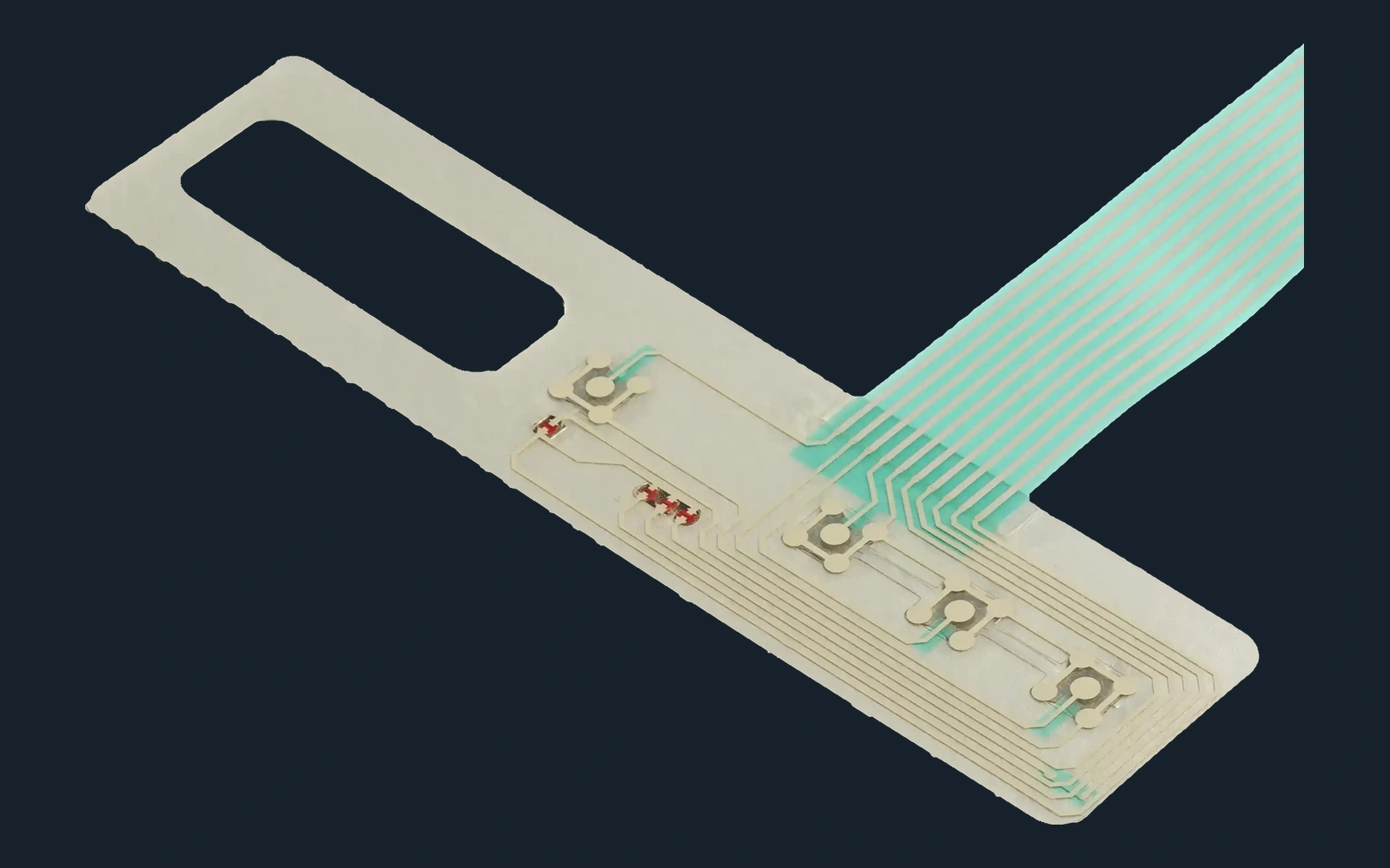
More current does not fix a poor optical path. It often makes hot spots, edge glow, panel bumps, heat, and neighboring-icon leakage more visible. Control the aperture and barriers first.
Assign every status, warning, mode, color, icon, priority, controller output, and failure condition.
Define LED, package, voltage, current, polarity, resistor, aperture, ink, diffuser, barrier, and viewing condition.
Use production artwork, overlay, spacer, circuit, LEDs, soldering, adhesive, tail, connector, and enclosure clearance.
Check current, polarity, icon clarity, off-state mask, hot spots, leakage, viewing angle, dimming, and key operation.
Control component source, color bin, files, BOM, fixture sequence, visual limits, records, packaging, and change notification.
Compare voltage, current, resistor, duty, color bin, polarity, soldering, aperture, diffuser, overlay, and viewing angle.
Inspect opaque ink, barrier, spacer edge, adhesive gap, display window, enclosure reflection, and LED placement.
Review package height, circuit support, spacer pocket, adhesive thickness, overlay stiffness, enclosure pressure, and solder profile.
Trace schematic, pinout, connector numbering, polarity, controller mapping, fixture sequence, artwork icon, and revision.
Power, warning, mode, and alarm indication integrated into a cleanable front interface.
Machine status, communication, fault, and active-function indication in compact panels.
Clear mode and process feedback around displays, navigation keys, and compact enclosures.
Low-profile status indication without a separate light pipe or indicator board.
Power, cycle, temperature, warning, and completion indicators integrated with printed keys.
Dead-front mode and status icons that appear only when active.
A list of LED colors is not enough. The quote review needs the electrical drive, icon behavior, viewing condition, optical stack, and approval method.
An LED membrane switch usually focuses on discrete status indicators or compact illuminated icons. A backlit membrane switch may also use light-guide film, EL, or another area-light architecture for broader keys and legends.
Yes, when the supply range, LED forward behavior, target current, duty, dimming, resistor value and power, package, placement, heat, tolerance, and test method are released.
Selective ink and optical apertures suppress the icon when unpowered and allow controlled light through when powered. Ink density, color, overlay texture, LED brightness, ambient light, and viewing angle must be balanced.
Use opaque ink layers, barriers, spacer geometry, controlled adhesive zones, diffusers, reflectors, edge masking, and separation from windows or adjacent icons. Test each LED independently.
Yes. Release each color or wavelength, package, forward voltage, current, polarity, state, icon, brightness relationship, sourcing rule, and acceptance condition.
Check every powered state, polarity, current, icon clarity, off-state mask, hot spots, crosstalk, viewing angle, ambient light, dimming, key operation, panel flatness, tail fit, connector, and enclosure clearance.
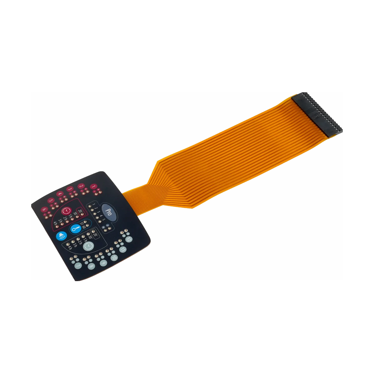
Compare discrete LED, light-guide film, EL, dead-front, and broader illuminated zones.
Review Route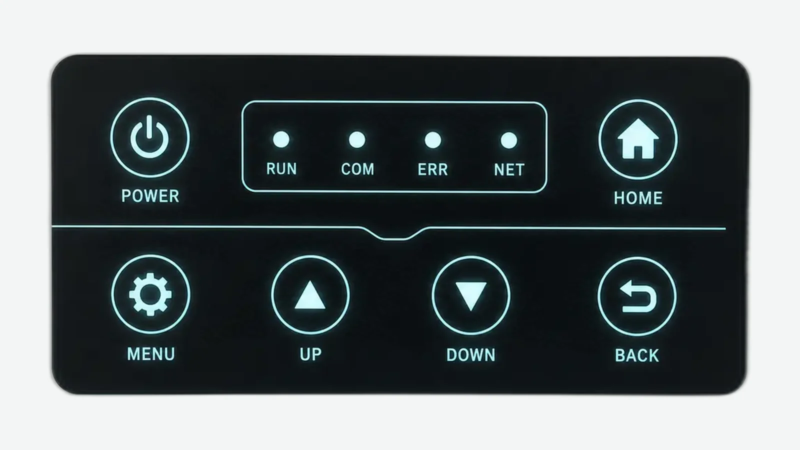
Review source behavior, optical stack, masking, power, and sample acceptance.
Review Route
Coordinate LED power, switch matrix, pinout, connector, shielding, and electrical test.
Review RouteJASPER can review LED selection, drive inputs, icons, optical barriers, circuit, tail, connector, enclosure clearance, and powered inspection before tooling.
Share the project basics. JASPER will review the stack, materials, connector, quantity, and production risks.