Dongguan, Guangdong 523927, China[email protected]+86 136 3262 5290
Home / Products / HMI Assembly / Custom Membrane Switch HMI Assemblies
SEALED LOW-PROFILE OPERATOR MODULES

Custom Membrane Switch HMI Assemblies

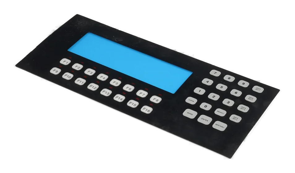
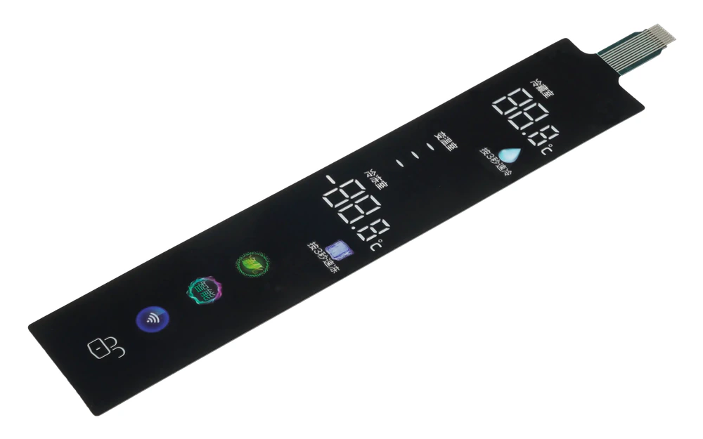
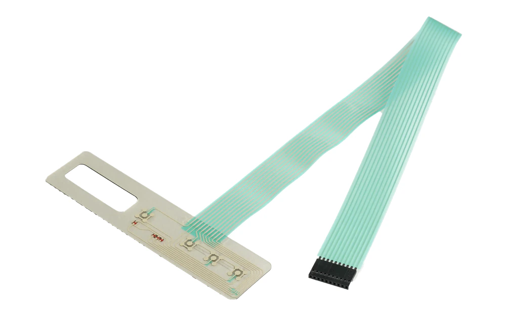
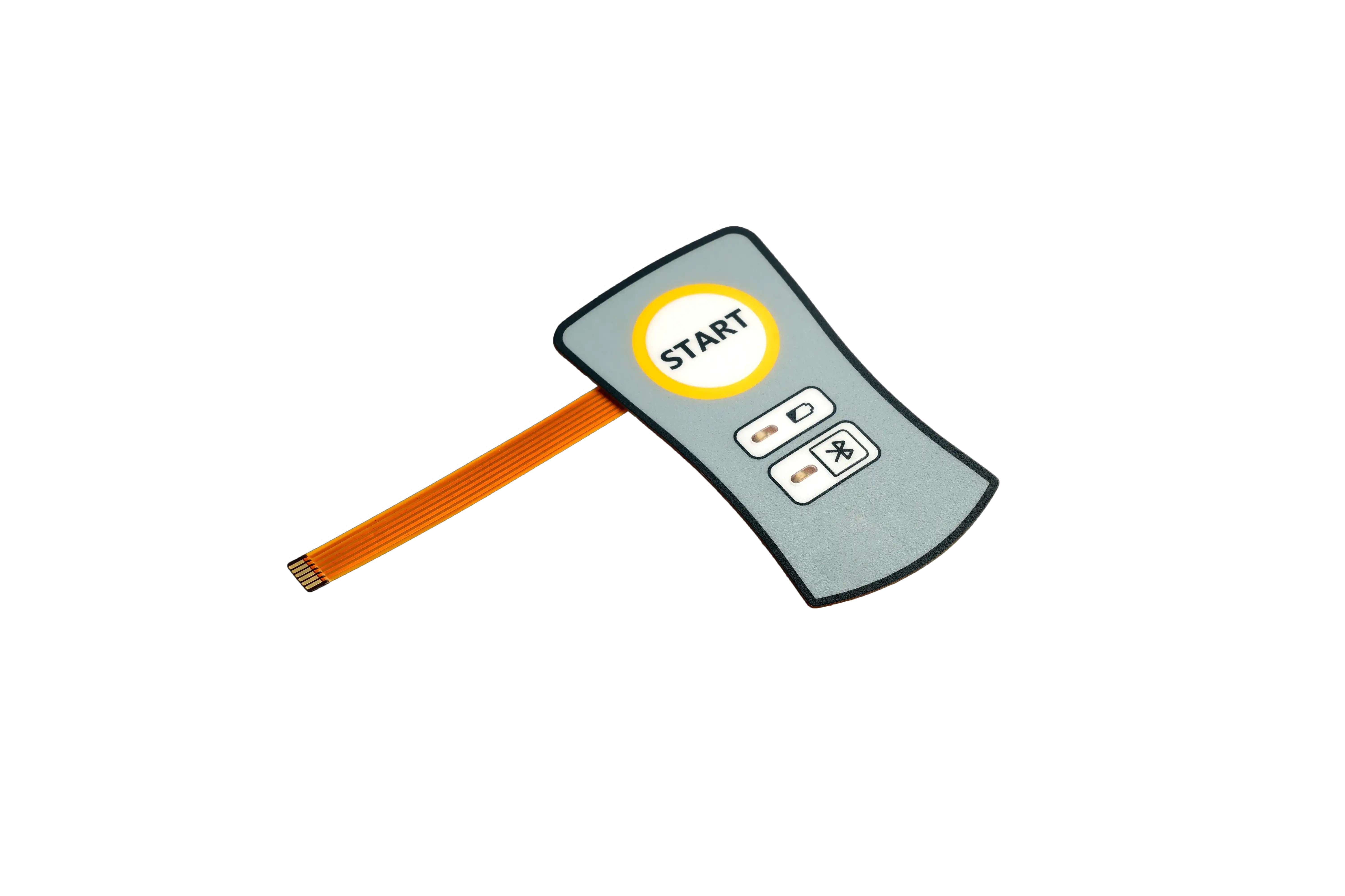
A membrane switch HMI assembly takes the low-profile printed input beyond a loose switch. The released module can combine the overlay, spacer and circuit stack, domes, LEDs, display window or named display, PCB or FPC, rear support, connector, gasket, fasteners, labels, and assembly-level checks required at the customer handoff.

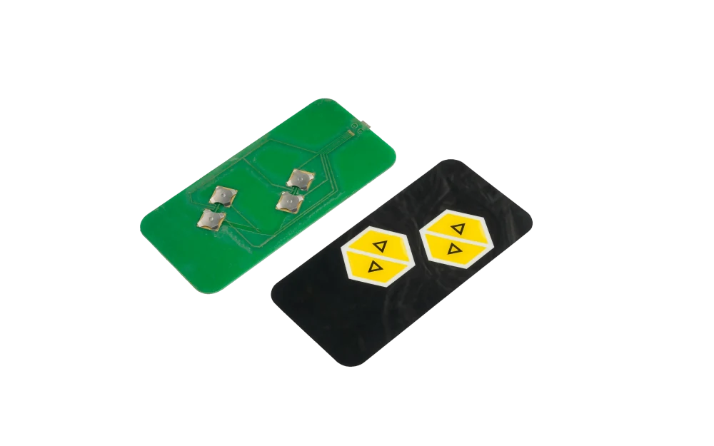
Custom membrane switch HMI assembly with printed front, display area, rear PCB, carrier, and connector
Input stack controlledgraphics, keys, domes, circuit, lighting, tail, and connector
Rear support releasedPCB or carrier, display relationship, mounting datums, gasket, and hardware
Assembly evidence definedappearance, continuity, actuation, lighting, fit, output state, and packaging

The Assembly Adds Integration Ownership Around the Membrane Switch

A custom membrane switch page owns the laminated input device. This route owns the larger customer handoff when that input must be aligned, supported, connected, mounted, protected, and checked with selected rear parts.

The module may be thin, but its tolerance chain is not simple. Overlay registration, dome support, window position, adhesive land, tail route, PCB height, connector access, gasket compression, and enclosure bosses all affect the installed result.

A drawing that shows a display or PCB does not automatically place it in the supply scope. Included, customer-supplied, and reference-only items must be separated in the bill of material and assembly notes.

Custom Membrane Switch HMI Assemblies fit when:

  • a membrane switch must arrive attached to a rear support, carrier, PCB, bezel, or enclosure interface
  • display or indicator geometry must stay registered to the printed operator surface
  • tail routing, connector access, gasket compression, and mounting datums need one assembly owner
  • the OEM can validate host software, machine behavior, and final compliance after integration

Six Release Controls for a Membrane-Based HMI Module

Most late assembly problems start at a boundary that looked obvious in the concept but was never dimensioned or assigned.

01

Front artwork and key map

Release control

Release active keys, dead areas, windows, indicator legends, embossing, cosmetic zones, and lit or unlit states.

If it is missing

The circuit works while the printed front miscommunicates the actual control state.

02

Switch stack and support

Release control

Define overlay, spacer, domes, circuit, backer, local support, venting, adhesive, and flatness at every active area.

If it is missing

Keys feel inconsistent because the rear structure does not support the approved switch stack.

03

Display and indicator relationship

Release control

Control clear aperture, viewing area, black mask, LED location, light block, display gap, and assembly datums.

If it is missing

Windows, icons, or indicators shift after the switch is attached to the rear module.

04

Tail and connector route

Release control

Release tail exit, bend zone, strain relief, connector model, keying, orientation, pinout, and enclosure clearance.

If it is missing

The assembly passes continuity but cannot be installed or connected without stressing the tail.

05

Gasket and mounting

Release control

Define gasket path, compression direction, studs, holes, fasteners, carrier, panel cutout, and installation sequence.

If it is missing

Mounting load distorts the switch or opens a sealing path around the finished front.

06

Test and packaging state

Release control

Name visual, dimensional, continuity, actuation, LED, display, fixture, labeling, protection, and pack checks.

If it is missing

An approved cosmetic surface or connector is damaged after test and before customer installation.

Release the Membrane HMI by Layer, Datum, and Customer Handoff

Each row should identify what JASPER supplies, what the OEM supplies, where the two meet, and what evidence confirms that boundary.

DecisionOptions to ReviewRelease Question
Operator frontPET or polycarbonate overlay, hard coat, embossing, windows, dead-front graphics, indicator colors, and cosmetic zonesWhich visible and tactile states become the approved master?
Input constructionTactile or non-tactile circuit, metal domes, spacer venting, LEDs, resistors, backer, shielding, and adhesiveWhich layers and electrical components belong to the supplied switch stack?
Rear assemblyPCB, FPC, carrier, bezel, bracket, display support, studs, fasteners, and labelsWhich rear parts arrive installed and which remain customer-installed?
InterconnectTail exit, bend limit, connector, pinout, cable, strain relief, board interface, grounding, and test accessWhat electrical and mechanical state exists at the customer connector?
InstallationPanel cutout, datums, gasket, compression, support, rear clearance, assembly direction, and service accessHow does the OEM install the module without changing the released switch behavior?
EvidenceAppearance, dimensions, continuity, actuation, force sample, LEDs, display check, fit fixture, traceability, and packagingWhich checks prove the module and which remain finished-system validation?
Exploded membrane switch HMI layers with overlay, circuit, display area, PCB, and carrier
STACK AND SUPPORT

Support Every Active Area Before Approving Key Feel

A dome or printed contact responds through the complete installed stack. Display openings, carrier pockets, PCB cutouts, adhesive gaps, fastener loads, and local enclosure ribs can change travel and force even when the loose membrane switch was approved.

  • mark the rigid support beneath every active key and dome
  • separate functional air paths from uncontrolled gaps
  • locate display, window, PCB, and switch layers from shared datums
  • approve representative edge, corner, and opening-adjacent keys in the assembly
Membrane switch HMI assembly positioned in a mechanical and electrical inspection fixture
ASSEMBLY PROOF

Check the Installed Connector and Mounting State, Not Only Continuity

Continuity confirms the circuit but not the finished module. The first article should reproduce connector access, tail bend, gasket compression, support, display or indicator state, fastener load, and the protected condition shipped to the integrator.

  • exercise keys after the assembly is mounted to its representative support
  • inspect windows and lighting in the intended viewing state
  • verify connector orientation and cable clearance with the mating interface
  • retain approved fixture results with the assembly revision

Release the Assembly Through Five Controlled Decisions

01

Map the operator front

Release artwork, keys, windows, indicators, tactile states, lighting, cleaning, and cosmetic boundaries.

02

Close the physical stack

Align overlay, switch circuit, display relationship, PCB or carrier, gasket, fasteners, datums, and rear clearance.

03

Release the interconnect

Confirm tail route, connector, pinout, board interface, grounding, strain relief, and test access.

04

Approve the assembled sample

Review appearance, dimensions, input feel, continuity, lighting, fit, connector state, protection, and packaging.

05

Control production changes

Lock materials, artwork, circuit, rear parts, fixtures, work instructions, substitutions, and requalification triggers.

Diagnose the Module at the Assembly Boundary

01

Keys change after mounting

Check rear support, PCB pockets, adhesive coverage, display opening, fastener load, gasket compression, venting, and enclosure flatness.

02

Window or legend is misaligned

Compare artwork datum, switch outline, display support, carrier location, adhesive placement, assembly fixture, and drawing revision.

03

Tail or connector cannot be installed

Review exit direction, bend keep-out, strain relief, keying, mating connector, enclosure ribs, service path, and pack protection.

04

Lighting or display state differs

Separate LED circuit, light block, display ownership, power state, connector output, host control, and complete-system validation.

Where Membrane Switch HMI Assemblies Fit

01

Industrial control fronts

Low-profile command panels assembled to rear support, indicators, connectors, and machine-facing mounting features.

02

Medical device modules

Cleanable printed controls with deliberate key states, windows, lighting, rear support, and integration evidence.

03

Laboratory instruments

Dense function keys and display areas held in one revision-controlled front module.

04

Test equipment

Membrane inputs combined with indicators, windows, circuit boards, connectors, and serviceable enclosure handoff.

05

Foodservice controls

Durable printed key panels integrated with lighting, display areas, gaskets, carriers, and repeatable mounting.

06

Transportation equipment

Thin operator modules coordinated with gloves, vibration support, night graphics, cable routing, and customer electronics.

RFQ PACKAGE

Send the Membrane Stack and Rear Assembly as One RFQ Package

A front artwork file and an exploded rear view are usually enough to expose the highest-risk interfaces before final drawings are complete.

  • front outline, artwork, key map, windows, indicators, embossing, lighting states, and cosmetic zones
  • overlay, spacer, domes, circuit, LEDs, backer, adhesive, shielding, venting, and material notes
  • display or window relationship, PCB or carrier, bracket, studs, fasteners, labels, and rear assembly drawing
  • tail exit, bend route, connector, pinout, cable, grounding, strain relief, and mating interface
  • panel cutout, enclosure model, mounting datums, gasket path, compression, clearance, and installation sequence
  • sample quantity, annual estimate, inspection, test fixture, packaging, traceability, and change-control requirements
Send Membrane HMI Files

Custom Membrane Switch HMI Assemblies FAQ

How is this different from a custom membrane switch?

A custom membrane switch is the laminated input device. This route adds the released rear support, display or indicator relationship, interconnect, connector, mounting, protection, and assembly-level evidence required at the customer handoff.

Can the PCB or display be included?

Yes, when the exact part, source, configuration, installation method, test scope, lifecycle responsibility, and replacement rule are listed in the quotation and bill of material.

Can the assembly be supplied with a gasket or mounting hardware?

Yes, when gasket material and path, compression, fasteners, studs, carrier features, installation direction, and customer enclosure datums are released together.

What testing is typical?

Projects may include appearance, dimensions, continuity, key actuation, lighting, connector output, display or indicator checks, and fit-fixture inspection. Finished-equipment behavior remains the OEM's validation.

What should the first article reproduce?

It should reproduce the production stack, rear support, tail route, connector, mounting load, gasket state, display or lighting relationship, protection, and packaging planned for repeat builds.

Related HMI and Interface Routes

Release the membrane input and its rear assembly from the same datums.

JASPER can review the printed front, switch stack, display or indicators, PCB or carrier, tail, connector, gasket, mounting, test evidence, and packaging as one membrane switch HMI assembly.

Start Membrane HMI ReviewContact Engineering