
A usable membrane switch design guide starts with the installed condition, not the pretty artwork. Define the layer stack, circuit, tactile response, tail, connector, adhesive, and sealing path before tooling, then approve a production-intent sample on the real housing.
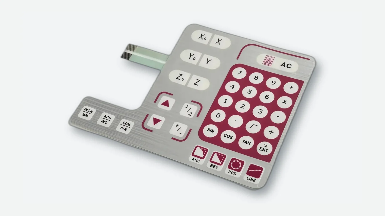
For commercial construction options after the design is framed, see custom membrane switches and the broader membrane switches product family. Pair this page with material and sealing references when the RFQ hardens.
1. Why design inputs decide field life
A membrane switch is a laminated user interface: a printed graphic overlay, one or more circuit layers, a spacer that holds contacts open, optional metal or poly domes, rear adhesive, and a flexible tail that ends in a connector. Typical finished stacks for industrial panels often land in roughly the 0.8–2.5 mm class before heavy backers, depending on domes and windows. Each layer adds thickness, tolerance, and a failure mode. When the adhesive land drops below a stable bond width on powder-coated steel, corners lift. When the tail bend radius is ignored, silver (Ag) traces on PET crack after a few cable-dress cycles. When a 180 g dome is copied onto a gloved HMI that needed ~350 g, operators miss presses.
Those failures rarely show up as a single “bad part” line on a packing list. They show up as intermittent opens, ghost keys after washdown, LED windows that yellow, or connectors that no longer seat after a service loop. The drawing looked finished; the installed condition was never specified.
Three early gaps create most rework:
- Artwork-only packages — colors and key legends without pinout, force, environment, or mounting surface.
- Bench-only samples — continuity checked on a flat desk, never on the production housing with real gasket pressure and cable routing.
- Late connector decisions — tail length and pitch chosen after the PCB layout freezes, forcing a redesign of the flex exit.
These gaps are preventable when the installed condition controls the drawing package. The rest of the article gives nine design criteria with acceptance evidence and release blockers, a step process from sketch to production release, and checklists you can paste into an RFQ. Related fundamentals live in how membrane switches work and membrane switch layer stack.
2. Nine membrane switch design considerations
Use the following membrane switch design considerations in roughly this order. Early mechanical and electrical choices constrain later cosmetic ones. Each criterion includes a acceptance evidence you can verify and a release blocker that should stop a release.
2.1 Installed condition and enclosure interface
Start with the host product, not the overlay. Tail exit side, connector clearance behind the panel, screw bosses, display bezels, gasket compression, and cable bend path change the stack more than font choice. Share the enclosure drawing or a section view with the interface cutout. A 0.5 mm interference at a boss can force a full re-layout of LEDs and keys.
Cutout dimensions, mounting surface material (ABS, PC/ABS, painted steel, powder coat), flatness notes, and cable path appear on the same package as the key layout.
Only a front-view PNG of the graphic, with “tail definition missing” and no land width for adhesive.
2.2 Layer stack and thickness budget
A common construction runs top to bottom as:
Graphic overlay (PET or PC) + hard coat / finish
Overlay adhesive
Dome retainer + metal/poly domes OR upper circuit only
Upper circuit (Ag ink on PET, or copper FPC)
Spacer (die-cut open cells at each key)
Lower circuit
Optional EMI shield / stiffener
Rear pressure-sensitive adhesive + liner
Flexible tail → connector
Spacer thickness sets free travel before contact. Domes add height and snap. Windows, dead-front ink, and light-guide film consume budget you cannot invent later. A thinner stack is not automatically better if dome travel collapses or adhesive bond area shrinks.
A stack table lists each film, adhesive, and approximate thickness with a total and a tolerance philosophy.
“Standard stack” with no thicknesses, no dome callout, and no note on whether the rear is adhesive-mount or gasket-retained.
2.3 Graphic overlay, finish, emboss, and windows
The overlay is the only layer the operator sees. Legends are usually printed on the second surface so abrasion and cleaners attack the film, not the ink. Polyester (PET) is the default for repeated flex and common industrial cleaners (IPA, mild detergents); polycarbonate (PC) is often chosen when optical clarity or certain forming needs dominate, with more caution on harsh chemicals and long flex life. Matte hard coats cut glare on factory floors; gloss can deepen color. Embossed rims or pillows help eyes-off key finding; emboss height is process-limited and must match film and tooling. Dead-front windows hide inactive indicators until lit.
| Overlay choice | Typical reason to pick it | Watch-outs |
|---|---|---|
| Polyester (PET) | Flex life, abrasion, common wipe-down chemicals | Optical depth may trail PC on some graphics |
| Polycarbonate (PC) | Clarity, certain formed/window looks | Harsher cleaners and long flex need extra review |
| Hard-coated PET | Glare control + scuff resistance on plant floors | Confirm coat vs named solvents (IPA, quaternary cleaners) |
| Selective textures | Finger guidance without full emboss | Texture in adhesive land can hurt wet-out |
Some programs also ask for plastic flammability context under the UL 94 family for enclosure-adjacent films. That request belongs on the material declaration pack; it is not an automatic rating of the finished keypad.
Vector artwork, Pantone or measured color targets, emboss drawing, window mask layers, and keep-out zones away from fold lines and adhesive edges.
Raster-only logos at key edges, no hard-coat callout for chemical wipe-down, emboss “as high as possible” without a number.
2.4 Circuit type, matrix, and electrical limits
Most custom OEM panels use silver conductive ink on polyester for flexible, multi-key layouts. Carbon overprints on silver pads are widely used to reduce wear and silver migration at the contact. Printed dielectric isolates crossovers. When current, fine pitch, or mechanical robustness outgrows printed silver, copper flexible printed circuit (FPC) or a rigid PCB subassembly takes over.
Industry RFQs often set contact resistance targets in the low tens of ohms when new and a higher life limit (multi-vendor design guides commonly discuss classes such as under about 50 Ω new and under about 100 Ω over life). Insulation between isolated nets is often specified in the high-megohm class (on the order of 100 MΩ). Treat those figures as common specification targets, not universal guarantees—trace length, connector, and environment move the result. Performance methods ordered under the ASTM F1578 membrane-switch test family are a frequent way buyers write sample acceptance without inventing a private lab method.
Schematic or pinout, matrix vs common-bus choice, max open/closed resistance targets, LED branch currents, and ESD/EMI notes if the host is noisy.
“Just make the keys work” with no pin map, no LED current, and no statement of whether the host expects a matrix scan or discrete lines.
2.5 Tactile response and dome force
Tactile panels use metal snap domes or embossed poly domes for a click. Non-tactile flat contacts trade the snap for lower profile and, in high-cycle flat designs, longer mechanical life at the contact. OEM design guides often discuss general tactile actuation in roughly the 180–350 g band, with higher forces for gloves or industrial duty and lower forces for light consumer panels. Travel is commonly discussed in roughly the 0.5–2.0 mm class depending on dome and spacer. Metal dome literature frequently cites multi-million actuation classes (sometimes up to about five million in vendor data); actual life depends on force, travel, contamination, and actuation style.
Force target with tolerance (for example 280 g ± 50 g), dome diameter family, tactile vs non-tactile decision tied to glove use, and a plan to feel physical samples.
Force copied from a phone app keyboard, mixed dome forces with no map, or “make it clicky” without a number.
For a focused comparison, see tactile vs non-tactile membrane switches.
2.6 Tail exit, bend radius, and connector
The tail is part of the circuit, not an afterthought cable. Exit side, length, stiffener, and connector pitch must match the controller board and assembly sequence. Common terminations include ZIF/LIF flex connectors (often 0.5 mm or 1.0 mm pitch families), crimped housings, solder tabs, and pin headers. Strain relief and minimum bend radius protect silver traces; a sharp 180° fold at the panel edge is a classic open-circuit source after a few service loops.
Tail length, exit orientation, connector manufacturer/series or pitch and pin count, mating cycle expectation, and a routing sketch inside the enclosure.
“Connector same as last project” without a part number, or a tail that must fold 180° immediately at the adhesive edge.
Detail reference: membrane switch connectors.
2.7 Adhesive, gasket, and sealing path
Rear pressure-sensitive adhesive must match the substrate’s surface energy, texture, temperature range, and cleaning chemicals. Smooth powder-coated metal and low-energy plastics do not take the same tape grade. Perimeter bond width matters: narrow lands peel. If the product claims an ingress rating, remember that IEC 60529 IP codes describe the evaluated enclosure configuration, not a loose switch on a desk. IP65-class language refers to dust-tight construction with resistance to water jets under the standard’s test conditions; IP67-class language refers to temporary immersion conditions as defined in the same framework. Tail exit, display windows, and gasket compression all sit on that sealing path.
Substrate named, minimum adhesive land, gasket drawing if used, and an explicit IP target with test orientation if sealing is required.
“IP67 membrane switch” called out as a free-standing part number with no housing, no tail seal method, and no test plan.
IEC 60529 defines enclosure protection codes. Use an IP designation only with a stated assembly configuration and test article. See also IP65 vs IP67 membrane switch design.
2.8 Environment, chemicals, UV, and EMI options
List real exposures: outdoor UV, −20 °C cold start, 70 °C cab heat, isopropyl (IPA) wipe-down, bleach-based disinfection, oil mist, vibration. PET overlays and hard coats are often selected for chemical and abrasion duty; outdoor legends need UV-stable films and inks. Industrial panels may add EMI/RFI shielding layers (printed carbon, ITO film, or metal foil) when the host fails EMC tests—shielding is an option, not a default. Automotive electronics programs may further require process documentation such as PPAP-style submissions or IMDS material data; those are program requirements, not automatic properties of every keypad.
Temperature range, chemical list, indoor/outdoor flag, and EMC context written as requirements.
“Industrial grade” with no temperature, no chemicals, and no EMC note on a motor-drive panel.
Material deep dive: membrane switch materials.
2.9 Documentation, samples, and production release
Design is not finished at artwork approval. You need a controlled BOM, revision block, pinout, stack table, inspection criteria, and a sample plan. First articles should prove actuation force, continuity, tail flex, adhesive wet-out, and any optical or sealing targets on the production-intent housing. Production release should freeze revision letters for graphic, circuit, and mechanical drawings together.
Revision-controlled PDF/DXF/AI package, sample quantity and accept/reject tests, and a change process for post-tooling edits. Material packs often include RoHS declarations under Directive 2011/65/EU and REACH SVHC communication under Regulation (EC) No 1907/2006 when the ship-to market requires them.
Verbal color changes after tooling, or production release based only on a photo of a bench sample.
Prototyping and lab paths: prototyping capabilities and quality testing.
3. How to design a membrane switch: step-by-step process
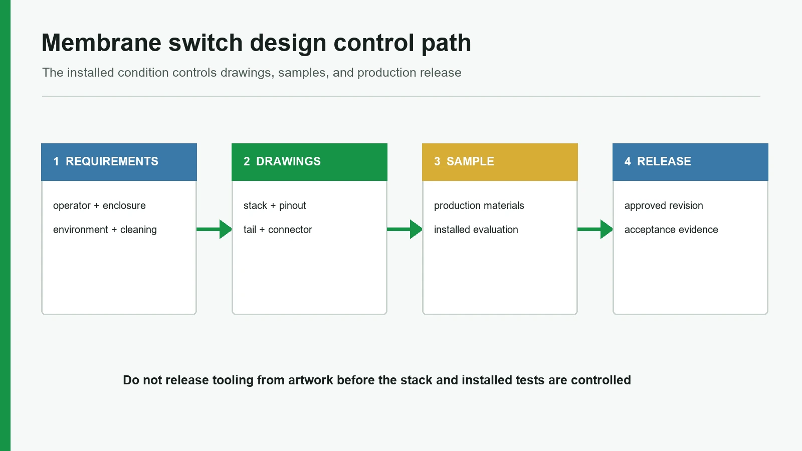
The following sequence turns the criteria into a project path. Teams that skip steps usually pay for them in sample loops.
Step 1 — Capture the operator and enclosure
Write down glove use, key count, viewing angle, cleaning method, and the cutout. Photograph the mounting surface. If replacing a legacy panel, measure the old stack and connector rather than guessing.
Step 2 — Choose architecture before artwork polish
Decide tactile vs non-tactile, PET vs PC overlay direction, printed silver vs copper FPC, adhesive-mount vs gasket-retained, and whether LEDs, dead-front, or shielding are in scope. A membrane keypad design guide mindset helps here: multi-key pitch, emboss map, and legend hierarchy are layout problems, not last-minute art tasks.
Step 3 — Build the drawing package
Include overall outline, key centers, emboss, windows, stack table, circuit schematic/pinout, tail exit and length, connector, adhesive keep-outs, and notes for force, temperature, and chemicals. Dimension critical interfaces to the enclosure, not only to artwork crop marks.
Step 4 — Run a stack-up and DFM review
Ask the fabricator to mark risks: land width, dome-to-spacer clearance, tail fold, ink trap at emboss, LED-to-window alignment. Resolve redlines before cutting production tooling. A short engineering review often costs less than a second tool.
Step 5 — Approve a production-intent sample
Mount the sample on the real housing. Check force feel, mis-press rate with gloves if relevant, LED visibility in the target ambient light, connector insertion, and any sealing or wipe-down tests you will later claim. Bench continuity alone is not enough.
Step 6 — Freeze revisions and release production
Lock graphic rev, circuit rev, and mechanical rev together. Confirm packaging, serialization if needed, and incoming inspection criteria. After release, treat changes as formal ECOs—especially connector pitch and key force.
A practical RFQ companion is the membrane switch RFQ checklist. Common drawing traps are listed in membrane switch design mistakes.
4. When this construction is the wrong choice
A membrane switch is a strong default for sealed, low-travel, graphic-rich control surfaces. It is not universal.
| Situation | Why a standard membrane stack struggles | Better direction to evaluate |
|---|---|---|
| Long key travel or mechanical keyboard feel is required | Membrane travel is short; domes do not recreate full mechanical switch travel | Mechanical switches or hybrid modules |
| Very high current loads on the keys | Silver ink traces are for signal-level switching | Copper FPC/PCB with appropriate contact design, or separate power switching |
| Deep 3D key shapes with large molded geometry | Flat film stacks have limited forming depth | Silicone rubber keypads or molded assemblies |
| Frequent harsh chemical immersion beyond film/ink capability | Overlay and adhesive systems have finite chemical windows | Different overlay systems, protective windows, or alternate HMI |
| Touch gestures, multi-touch, or zero-force flush glass look as primary UX | Capacitive sensing and membrane contact are different architectures | Capacitive touch panels (with their own EMC/glove limits) |
| Field-replaceable single keys with serviceable switches | Membrane is usually a full laminated assembly | Discrete switches on a PCB with a separate overlay |
Saying “no” early is part of a responsible membrane switch design guide. Forcing a film stack into a deep silicone-feel brief, or into a power-switching brief, creates chronic field complaints no amount of artwork polish will fix.
5. Drawing inputs and sample approval checklists
5.1 Drawing input checklist
| Input | Why it matters | Owner usually |
|---|---|---|
| Enclosure cutout + section | Sets land, tail exit, boss interference | Mechanical |
| Overlay material & finish | Abrasion, chemicals, glare | Mechanical engineering / industrial design |
| Key map, legends, languages | Tooling and print plates | ID / marketing |
| Emboss / dead-front / windows | Tooling and optical path | ID / EE |
| Stack table with thicknesses | Feel, fit, gasket crush | Mechanical engineering + manufacturer |
| Circuit type & pinout | Host firmware and connector | EE |
| Force / life targets | Dome and spacer choice | Mechanical engineering / user experience |
| Tail length, exit, bend notes | Assembly and reliability | Mechanical engineering / electrical engineering |
| Connector P/N or pitch + pins | Mating hardware | EE |
| Adhesive substrate & environment | Bond reliability | Mechanical engineering |
| IP / EMC / chemical list | Materials and test plan | System / quality |
| Artwork files (vector) + rev block | Manufacturability | ID |
| Sample tests & accept limits | Prevents subjective approval | Quality |
| Annual volume & packaging notes | Process and cost structure | Purchasing |
5.2 Sample approval test matrix (minimum)
| Check | On bench only? | On housing? | Notes |
|---|---|---|---|
| 100% key continuity / matrix scan | Required | Required | Catch opens and bridges |
| Actuation force sample keys | Useful | Required | Feel changes with support stiffness |
| Tail flex / dress path | Optional | Required | Failures hide until cable is routed |
| Connector mate cycles (sample count) | Optional | Required | Confirm stiffener and insertion force |
| LED / dead-front appearance | Partial | Required | Ambient light differs in enclosure |
| Adhesive wet-out / edge lift after dwell | Partial | Required | Surface energy is real-world |
| Wipe with named chemicals | Optional | As specified | Use the actual cleaner list |
| Sealing / IP configuration (if claimed) | Not sufficient alone | Required | Per IEC 60529-style assembly intent |
6. Frequently asked questions
What should a membrane switch design guide cover before tooling?
It should cover installed enclosure conditions, layer stack, overlay and emboss, circuit and pinout, tactile force, tail and connector, adhesive and sealing path, environmental loads, and the sample tests that freeze production. Artwork without those inputs is not a release package.
How do you design a membrane switch for a first prototype?
Lock architecture (tactile or not, film family, circuit type), produce a dimensioned stack and pinout, then build a small sample lot. Approve feel and fit on the real housing before cutting hard production tooling for complex emboss or high-volume print sets.
What are the most important membrane switch design considerations for RFQs?
Pinout, force targets, environment, mounting surface, tail/connector, and acceptance tests move price and risk more than logo colors. Suppliers cannot quote a stable construction from a flat graphic alone.
Is a membrane keypad design guide different from a single-button design?
Yes. Multi-key pitch, emboss maps, legend hierarchy, matrix wiring, and mis-press risk dominate keypad work. Single-status buttons still need stack and sealing discipline, but layout density is lower.
Which overlay film should be the default, PET or PC?
PET is the usual default for flex life and frequent chemical wipe-downs. PC is often considered when optical clarity or specific forming needs dominate. Match the film to cleaning agents and flex duty rather than habit.
What connector belongs on the flexible tail?
Specify the mating connector series the controller already uses, or state pitch, pin count, and orientation if the series is open. ZIF/LIF flex connectors are common for dense tails; crimped housings appear when serviceability or harness norms require them.
Can a project claim IP65 or IP67 on the membrane switch alone?
Treat IP language as an assembly result under IEC 60529-style testing of the configured product. The switch contributes edge bond, tail exit, and window design, but the housing, gasket, and test setup complete the rating.
How many samples are enough before production release?
Enough to cover dimensional fit, electrical function, and the riskiest environmental checks the program will claim—typically more than a single showpiece unit. Exact quantity depends on key count, tooling risk, and quality plan; define accept/reject before the samples ship.
When is copper FPC a better circuit base than printed silver?
When current, fine pitch, mechanical abuse, or routing density exceeds what printed silver on PET can support reliably. Signal-level panels often remain on silver; power-adjacent or high-density designs often move to copper.
7. What to do next
A membrane switch design guide is only useful if it changes the package you send. Before the next RFQ, assemble the enclosure cutout, stack intent, pinout, force target, connector, environment list, and sample tests. Use the nine criteria as a redline checklist. If a construction fails the “when not to use it” table, stop and change architecture rather than polishing artwork.
Technical References
- Source: ASTM F1578 membrane switch contact closure cycling practice. Accessed 2026.
- Source: IEC 60529 enclosure protection classification. Accessed 2026.
- Source: IEC 60068 environmental testing method series. Accessed 2026.
- Source: 3M 467MP and 9495LE technical data. Accessed 2026.
- Source: Covestro Makrofol and Bayfol Film Selector Guide. Accessed 2026.
- Source: Snaptron metal dome venting and actuator guidance. Accessed 2026.
- Source: TE Connectivity FPC connector product drawings. Accessed 2026.
- Source: UL 969 marking and labeling systems scope. Accessed 2026.
- Source: IPC-D-325 documentation requirements for printed boards and assemblies. Accessed 2026.
- Source: IPC-6013 qualification and performance specification for flexible circuits. Accessed 2026.
- Source: ISO 9241-210 human-centred design for interactive systems. Accessed 2026.
- Source: IPC-2223 flexible circuit design standard. Accessed 2026.
- Source: IEC 62368-1 product safety standard. Accessed 2026.
Release one controlled membrane switch design package
Send the enclosure drawing, artwork, key map, circuit requirements, tail path, connector, exposure, and sample acceptance criteria.