
The design mistakes that cause the most disruption are usually unresolved interfaces, not missing artwork. A membrane switch drawing is ready for tooling only when the operator, enclosure, layer stack, adhesive, display openings, tactile mechanism, tail, connector, sealing path, lighting behavior, and sample acceptance method describe one buildable assembly.
A clean front graphic can hide contradictory assumptions below it. One supplier may price a flat printed circuit, another may assume metal domes, and the enclosure team may already have frozen a tail path that neither construction can use. The review below is intended to expose those gaps while the drawing can still be coordinated.
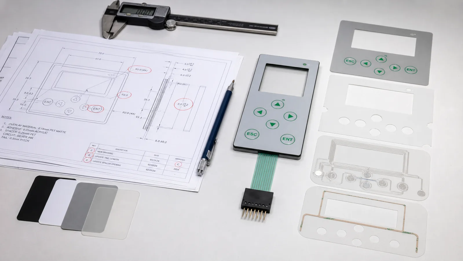
Why a complete-looking drawing can still be unready
Tooling release is not only permission to cut shapes. It also releases printing screens, circuit artwork, spacer geometry, embossing details, inspection fixtures, and material purchasing. A later change may touch several of those items even when the visible edit looks small.
The practical test is simple: can manufacturing, quality, the enclosure team, and the electronics team read the same file and reach the same construction? If they cannot, the drawing is visually complete but technically open. Mark unresolved choices as open items instead of letting them become silent supplier assumptions.
Treating the membrane switch as a flat label
The visible overlay is only one part of the interface. The circuit pattern, spacer openings, tactile element, rear adhesive, tail, connector, rigid support, display window, lighting, and enclosure all influence whether a key feels and functions as intended.
A front-view PDF is useful artwork, but it is not a construction definition. Add a section view or layer schedule and identify which features belong to the switch supplier, enclosure, PCB, and final assembler.
- Signal on the drawing
- The package contains front artwork and an outside profile, but no layer stack, circuit reference, connector detail, mounting surface, or interface ownership.
- What it can affect
- Suppliers can quote materially different constructions under the same part number, making price, thickness, tactile feel, sealing, and approval results impossible to compare.
- Confirm before tooling
- One controlled stack-up, overall thickness basis, circuit technology, tactile method, mounting method, tail termination, and responsibility for every opening and support feature.
Defining key geometry without defining the operator
Key diameter and spacing should follow the person and task, not just the available graphic area. Bare fingers, gloves, wet hands, limited visibility, repeated operation, and accidental activation create different priorities for pitch, force, embossing, legend size, and separation between commands.
Do not resolve ergonomics by importing a dimension from another product. Record the operating scenario, then evaluate a production-intent keypad in the intended orientation with the people who will use it.
- Signal on the drawing
- Key centers and outlines are dimensioned, but the file says nothing about gloves, viewing angle, operating posture, required feedback, or prevention of adjacent-key activation.
- What it can affect
- A layout can pass electrical inspection yet feel ambiguous, fatigue the operator, or invite the wrong command in actual use.
- Confirm before tooling
- Primary user groups, glove condition, key hierarchy, intended tactile or non-tactile response, actuation target, visual constraints, and the user evaluation planned for the first representative sample.
Selecting the face film and adhesive after the enclosure is frozen
Generic labels such as PET, PC, or acrylic adhesive do not define a reliable material system. Film grade, texture, hard coat, print compatibility, window clarity, flex behavior, chemical exposure, UV exposure, and cleaning method can change the correct choice within the same polymer family.
Adhesive selection also begins with the actual mounting surface. For example, 3M positions its 467MP transfer tape for metals and high-surface-energy plastics, while 9495LE is designed for many low-surface-energy plastics and powder-coated paints. That distinction is a reason to test the real substrate, not a recommendation to use either product by default.
- Signal on the drawing
- The bill of materials says only 'polyester overlay' or 'rear adhesive,' while the enclosure material, coating, texture, flatness, surface preparation, and cleaning exposure are missing.
- What it can affect
- The overlay may show premature wear or optical change, and the assembly may lift at edges, bridge surface texture, or bond inconsistently during installation.
- Confirm before tooling
- Film manufacturer and grade or approved equivalent, surface finish and hard coat, ink system, cleaning and exposure list, enclosure substrate and coating, prepared surface condition, adhesive family, lamination process, and validation coupon or sample.
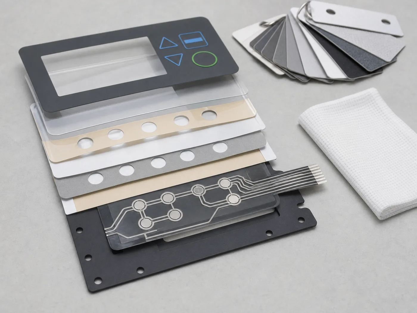
Using different tolerance references for windows, embossing, and cutouts
A display window may be dimensioned from the outer edge, the printed border may be positioned from artwork, and the enclosure opening may use a third origin. Each drawing can be internally correct while the assembled window still shows an uneven border.
Build one datum strategy through the overlay, circuit, adhesive, locating features, and enclosure. Separate genuinely critical relationships from general outline tolerances, and state whether inspection is performed on a free part, a fixture, or the assembled panel.
- Signal on the drawing
- Printed apertures, die-cut windows, embossed keys, LED holes, and housing openings have dimensions but no shared datum, registration target, or assembly inspection condition.
- What it can affect
- Tolerance stacks become visible as clipped legends, off-center windows, domes that do not sit beneath the printed key, or adhesive exposed inside an opening.
- Confirm before tooling
- Functional datums, critical feature relationships, print-to-cut registration basis, window and emboss alignment, inspection condition, and which tolerance belongs to each manufacturing process.
Choosing a tactile dome without coordinating support and venting
A metal dome does not create the final key feel by itself. Actuator alignment, overlay stiffness, spacer pocket, circuit pad, backing support, preload, over-travel, and the path available for displaced air all contribute to the response at the finished panel.
Dome manufacturers such as Snaptron describe venting through a spacer path, the carrier, or the board because trapped air can change tactile response. The correct path depends on the stack and sealing strategy; it cannot be added as an isolated afterthought.
- Signal on the drawing
- The BOM names a dome series or force, but the section view omits the actuator, support surface, pocket, allowable travel, dome retention, and air path.
- What it can affect
- Keys can feel inconsistent across the panel, require unintended force, lose a clear snap, suffer off-center loading, or conflict with environmental sealing.
- Confirm before tooling
- Dome geometry and approved source, force tolerance, actuator location, support flatness, spacer pocket, venting concept, retention method, over-travel control, and tactile approval method in the final housing.
Freezing the tail and pinout before checking the assembly path
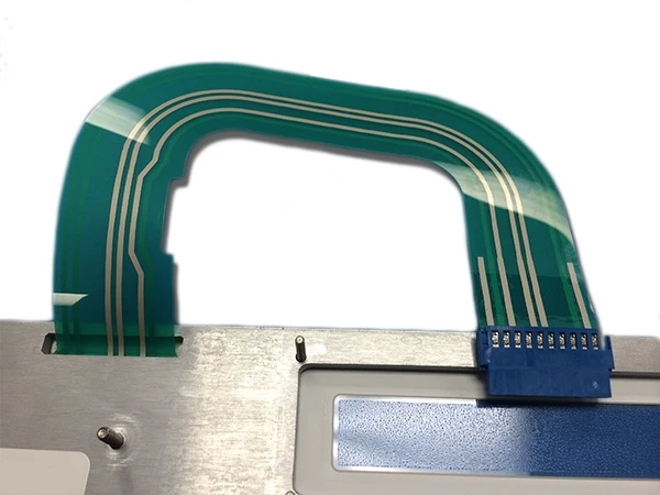
The shortest tail on the drawing is not always the easiest tail to install. Exit direction, bend location, moving covers, sharp edges, connector access, insertion order, service position, strain relief, stiffener, and controller-board orientation must be reviewed together.
The selected connector drawing controls details such as pitch, contact side, accepted flex thickness, exposed conductor geometry, and actuator operation. Those details must match the membrane tail. Pin assignments should remain open until circuit routing and controller constraints have been reviewed together.
- Signal on the drawing
- The tail outline and pin numbers are fixed, but there is no routed enclosure view, contact-side callout, stiffener detail, connector manufacturer drawing, or assembly sequence.
- What it can affect
- The tail can emerge on the wrong side, fold across a critical area, enter the connector with contacts reversed, require an avoidable circuit crossover, or become inaccessible during final assembly.
- Confirm before tooling
- Tail exit and routing envelope, static and service positions, bend and strain-relief zones, connector part and revision, pitch, contact orientation, flex thickness, stiffener, exposed contacts, pinout ownership, and insertion sequence.
Treating waterproof performance as a property of the loose switch
IEC 60529 classifies protection provided by enclosures. For a membrane interface, the practical protection path crosses the overlay edge, adhesive, display openings, tail exit, connector route, housing joints, fasteners, gaskets, surface defects, and installation process.
An IP label without an agreed test article is incomplete. Define whether the claim applies to a finished product, a front-panel assembly, or another configuration, and document the orientation, preconditioning, openings, cable state, and pass criteria used in evaluation.
- Signal on the drawing
- The title block calls for an IP level, but the switch boundary, enclosure drawing, test configuration, tail path, vent route, and treatment of display openings are not referenced.
- What it can affect
- A supplier can deliver a well-sealed switch that still leaks through the panel interface, or the completed equipment can be tested in a configuration different from the one the drawing implies.
- Confirm before tooling
- Protected enclosure, interface boundary, complete sealing path, substrate condition, opening treatment, tail and connector route, assembly process, test standard and configuration, preconditioning, and acceptance record.
Leaving backlighting and off-state appearance until the graphic is finished
Lighting changes more than the addition of an LED. It affects ink density, white layers, masking, diffuser or light-guide geometry, spacer thickness, current and connector pins, thermal concentration, display-window appearance, and the colors seen in both lit and unlit states.
Define what the operator must see, from which angle, in which ambient light, and whether the requirement is a status indicator, a uniformly illuminated legend, or a concealed dead-front icon. Approve both states in the intended enclosure.
- Signal on the drawing
- Artwork shows translucent legends or status symbols, but there is no optical stack, light source, mask, diffuser, off-state target, viewing condition, electrical interface, or brightness acceptance method.
- What it can affect
- The sample may show hotspots, light leakage, color shift, uneven legends, visible hidden icons, or acceptable bench performance that disappears under real ambient light.
- Confirm before tooling
- Lit functions, light-source layout, optical layers, ink and mask strategy, color targets, power and pin allocation, viewing angle, ambient-light conditions, off-state appearance, enclosure color, and approval sample.
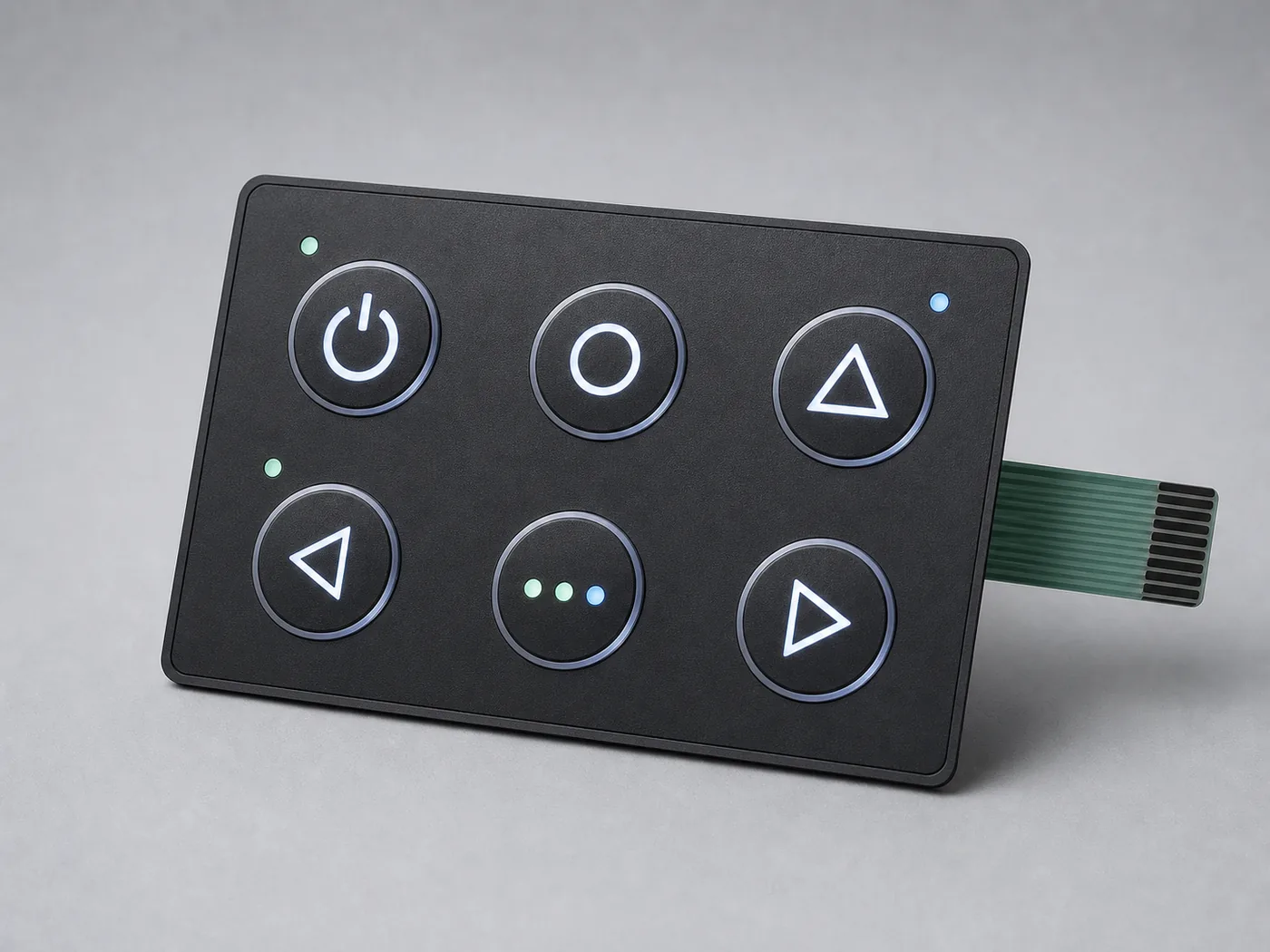
Ordering a sample without defining what the sample must prove
A cosmetic mock-up can validate artwork but cannot approve electrical behavior, adhesive performance, tactile response, lighting, or sealing. Conversely, an electrically functional sample built with substitute graphics or adhesive cannot close the visual and mounting requirements.
State the intent of every sample and identify any non-production material or process. Final approval should use a production-intent build installed on the representative enclosure, with an acceptance matrix that separates visual, dimensional, tactile, electrical, optical, assembly, and environmental checks.
- Signal on the drawing
- The purchase request says 'prototype for approval' but does not identify construction fidelity, substitutions, test fixtures, enclosure samples, measured characteristics, reviewers, or change-control status.
- What it can affect
- Different teams can approve different aspects of different samples, leaving no single configuration that proves the released design is acceptable.
- Confirm before tooling
- Sample level, production-intent materials and processes, declared substitutions, sample quantity, representative housing, inspection and test matrix, responsible approvers, recorded results, deviation handling, and the revision that approval releases.

Pre-tooling membrane switch drawing checklist
Use this list as a release gate, not as a substitute for project-specific engineering. Any item that is unknown should remain an open action with an owner and due date.
- The operator, glove condition, viewing condition, and critical commands are defined.
- One section view or layer schedule controls the full construction and overall thickness basis.
- The overlay film grade, texture, hard coat, ink system, and exposure list are identified.
- The enclosure substrate, coating, texture, flatness, cleaning method, and surface preparation are known.
- The rear adhesive is selected against the actual substrate and installation process.
- Functional datums align print, cuts, embossing, windows, domes, LEDs, adhesive, and housing features.
- Critical tolerances name the controlling process and inspection condition.
- The tactile element, actuator, support, spacer pocket, travel control, retention, and venting concept are coordinated.
- The circuit drawing identifies key map, contact arrangement, routing constraints, shielding needs, LEDs, and test points.
- Tail exit, routing envelope, bend and strain-relief zones, stiffener, exposed contacts, and assembly sequence are shown.
- The connector part, revision, pitch, contact side, accepted flex thickness, and pinout ownership are controlled.
- The sealing claim is tied to a defined enclosure, interface boundary, assembly process, and test configuration.
- Lighting requirements cover source, masking, optical layers, color, uniformity, leakage, viewing conditions, and off-state appearance.
- The production-intent sample and every allowed substitution are defined before approval begins.
- The acceptance matrix assigns visual, dimensional, tactile, electrical, optical, assembly, and environmental checks to named reviewers.
- The drawing revision, linked specifications, approved deviations, golden sample, and change process identify one released configuration.
What to include in the release package
Keep the controlled information together so the quotation, sample, inspection plan, and repeat order all point to the same design.
Mechanical and graphic definition
- Dimensioned outline, cutouts, datums, critical tolerances, and section view
- Vector artwork with print colors, textures, windows, embossing, and dead-front states
- Enclosure model or drawing showing the mounting surface, support, openings, and assembly access
Electrical and interconnect definition
- Circuit schematic or key matrix, contact map, LEDs, shielding needs, and electrical test requirements
- Tail route, stiffener, exposed-contact geometry, connector manufacturer drawing, and controlled pinout
- Controller interface information needed to resolve routing, grounding, and power allocation
Use environment and validation
- Operating, storage, cleaning, UV, moisture, contamination, and user conditions that affect materials
- Applicable equipment standards and the exact assembled configuration to be evaluated
- Sample stages, acceptance matrix, measurement method, representative housing, and approvers
Commercial and change control
- Prototype and production quantities, packaging needs, and forecast assumptions used for quotation
- Drawing revision, linked specifications, approved alternatives, deviation process, and golden-sample status
- Named technical contacts for graphics, enclosure, electronics, quality, and purchasing questions
Reference points used in this guide
These sources establish the boundaries behind several recommendations. The selected part drawing, project specification, and validation plan remain controlling.
- 01
IEC 60529, Degrees of protection provided by enclosures
Used to distinguish an enclosure IP classification from an unsupported rating for a loose membrane switch.
- 02
IEC 61000-4-2:2025, electrostatic discharge immunity test
Used to frame ESD as an equipment-level test requirement that must be defined before a shielding or grounding stack is released.
- 03
3M 467MP technical data and 9495LE product data467MP9495LE
Used to illustrate why high- and low-surface-energy substrates cannot be covered by a generic rear-adhesive callout.
- 04
TE Connectivity FPC connector product data
Scope: contact side, pitch, actuator style, and accepted flex thickness belong to the selected connector definition.
- 05
Snaptron guidance on dome venting
Used to support coordinated review of the dome, spacer, air path, support surface, and finished tactile response.
- 06
Covestro Bayfol and Makrofol film selector
Used to demonstrate that membrane-switch films are specified by grade, surface, and function rather than by polymer acronym alone.
Membrane switch design review FAQ
Short answers to the questions that usually decide whether a drawing should be released or returned for coordination.
How do I know whether a membrane switch drawing is ready for tooling?
It is ready when the drawing and linked specifications define one construction that the supplier, enclosure team, electronics team, quality team, and assembler interpret the same way. Open choices about the operator, layer stack, material grade, adhesive substrate, datums, dome support, tail, connector, sealing, lighting, and acceptance method should be closed or formally identified as controlled supplier proposals before release.
Should the membrane switch supplier choose the adhesive?
The supplier can recommend an adhesive, but the customer must provide the real substrate, coating, texture, flatness, cleaning method, exposure, installation pressure, and service load. Selection should be documented as a joint engineering decision and verified on the representative enclosure surface rather than treated as an unnamed standard adhesive.
Can a membrane switch itself be specified as IP65 or IP67?
An IP claim should identify the enclosure or assembled configuration being evaluated. The switch can contribute an important sealing layer, but edges, openings, adhesive, tail exit, connector routing, housing joints, gaskets, fasteners, and installation all participate. Tie the requested classification to a defined test article and test configuration.
When should the tail pinout be frozen?
Freeze it after the connector, contact side, accepted flex thickness, controller constraints, tail routing, and circuit layout have been reviewed together. Early pin flexibility can simplify routing; late unrecorded pin changes can create a serious interface error. The released pinout needs one clear owner and revision.
What should a production-intent membrane switch sample prove?
It should prove the questions named in the acceptance matrix using the intended materials, stack, dome or contact system, tail, connector, adhesive, graphics, lighting, and representative enclosure. Any substitute material or process must be declared so reviewers know which conclusions can and cannot be carried into production approval.
What files should be sent for a membrane switch design review or RFQ?
Send the dimensioned drawing, vector artwork, layer or section definition, circuit and key map, tail and connector details, enclosure drawing or model, substrate and finish, operating and cleaning conditions, lighting requirements, applicable equipment tests, prototype and production quantities, and the acceptance questions the first sample must answer.
Resolve the open interfaces before tooling release
Send the current drawing, artwork, circuit and connector information, enclosure context, operating exposure, quantities, and the questions the first sample must answer. JASPER Engineering will return a focused list of decisions needed for quotation and a production-intent build.