
Review the stack
Identify every layer, material, thickness, liner, print state, adhesive, tail, window, key, vent, gasket, backer, and mating datum.
JASPER converts printed and unprinted films, circuit layers, spacers, adhesives, gaskets, liners, and support materials into aligned interface components. The cutting route is selected from material behavior, feature geometry, volume, cosmetic risk, registration, edge condition, tooling, and the next assembly step.
A cut feature can control graphics, key travel, venting, electrical clearance, adhesive land, display visibility, seal path, connector fit, and assembly registration. JASPER reviews the complete stack and chooses tooling and sequence from the released geometry, material, thickness, print state, liner, volume, and acceptance criteria. Exact tolerance requires the real combination and a project review.
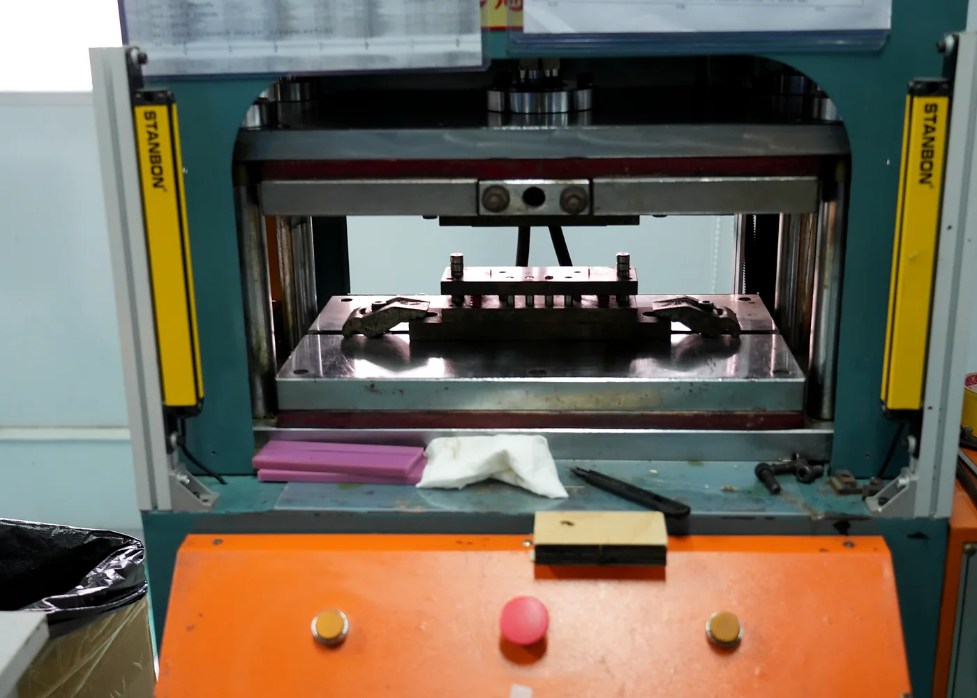
The die-cutting plan should anticipate how each layer is printed, handled, laminated, inspected, and installed.
Identify every layer, material, thickness, liner, print state, adhesive, tail, window, key, vent, gasket, backer, and mating datum.
Select through cut, kiss cut, steel rule, hard tool, plotter, laser or other reviewed route; define nesting, registration, waste, tabs, handling, and sequence.
Inspect dimensions, registration, edge, burr, debris, adhesive exposure, liner release, windows, slits, vents, flatness, appearance, and assembly fit.
Link active cut files, tooling ID and condition, materials, setup, inspection, approved sample, packaging, maintenance, deviations, and engineering changes.
The same outline can have different acceptance risks depending on whether it controls optics, electrical spacing, key travel, bonding, sealing, or installation.
| Layer or feature | Controls to define | Risk if left open |
|---|---|---|
| Graphic overlay and windows | Print-to-cut datums, window position, edge, cosmetic surface, tabs, liner, protective film and viewing area | Clipped graphics, visible edge defects, window misalignment or handling damage |
| Spacer, dome and vent features | Key openings, dome pocket, vent path, channel width, adhesive exposure, registration and debris control | Poor key response, trapped air, dome damage, contamination or short circuit |
| Circuit, tail and connector | Trace clearance, contact zones, tail outline, bend zone, stiffener, connector pads, slits and insulation | Open/short risk, pinched tail, connector mismatch or cracked conductor |
| Adhesive, gasket and liner | Kiss-cut depth, release liner, pull tab, waste removal, seal land, corner radius, application sequence and storage | Edge lift, exposed adhesive, blocked vent, poor seal path or assembly error |
Provide the complete converted stack and next assembly step so the tool does not optimize one layer while breaking another.
JASPER can review graphic films, printed circuits, spacers, adhesives, gaskets, liners, insulation, support layers, tails, windows, vents, tabs, and related custom interface materials.
No. Tolerance depends on material, thickness, feature, tool, registration, print or adhesive state, volume, environment, measurement, and edge requirement. Quote the defined construction.
Kiss cutting can leave a carrier or release liner intact for adhesive parts, gaskets, labels, or assembly aids. Depth, liner, pull tab, waste removal, storage, and application sequence must be specified.
They should close dimensions, print/circuit registration, edge and debris, liner and adhesive behavior, windows, vents, tails, fit, handling, protection, packaging, and the planned inspection method.
Send the cut files, materials, liners, artwork/circuit datums, assembly sequence, quantities, and critical features for review.
Share the project basics. JASPER will review the stack, materials, connector, quantity, and production risks.