
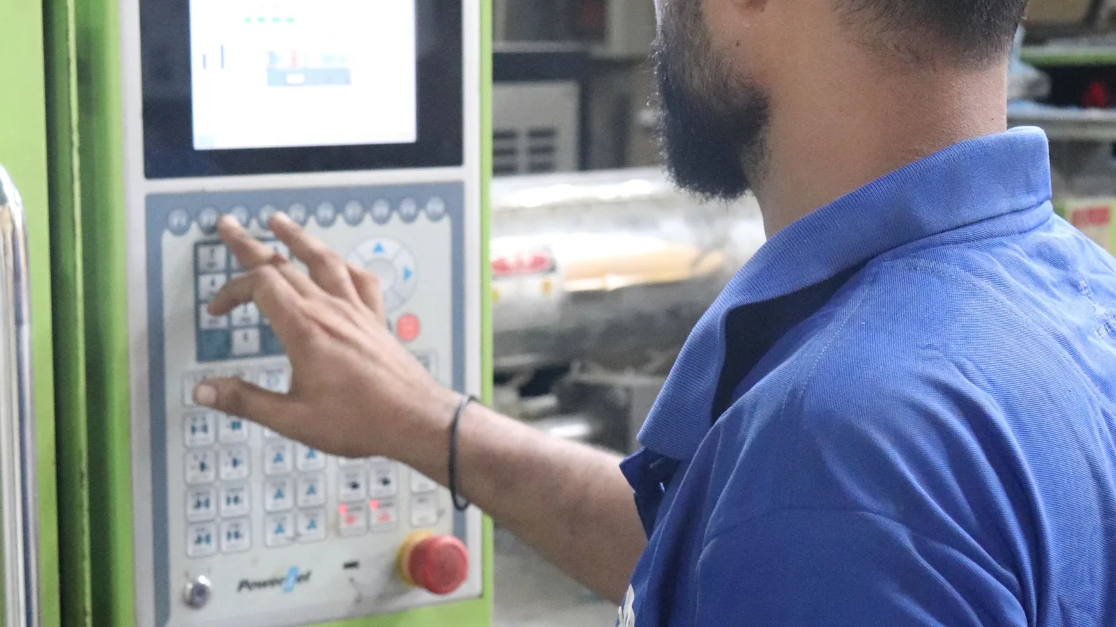
Rugged is not a construction
Industrial control panel membrane switches become reliable only after the operator, exposure, mounting surface, cable path, and machine-control boundary are defined. These four decisions should be visible before artwork approval.
- Map the shiftList who operates, sets up, cleans, and services the panel, with gloves, lighting, press frequency, and control consequence.
- Name the exposureOil, coolant, cleaner, dust, water, heat, vibration, and abrasion require separate inputs and acceptance checks.
- Release the mountingPanel finish, flatness, adhesive land, tail slot, connector, grounding, and service clearance belong on the assembly drawing.
- Approve it installedUse the intended enclosure and cable route; the machine builder validates safety functions and finished equipment.
Industrial controls start with the machine task
A packaging line, pump controller, test instrument, and mobile pendant can all use an industrial membrane switch, yet they do not share the same key map or exposure. Start with what the operator does during production, changeover, fault recovery, and service, then design the interface around that sequence.
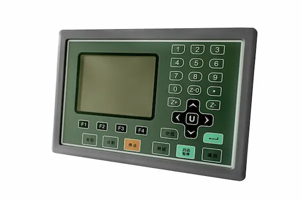
Packaging and automated production lines
Fillers, sealers, labelers, conveyors, inspection stations, and compact machine-control panels.
Operators repeat start, pause, jog, recipe, and fault-recovery actions across long shifts. Gloves, film dust, product residue, cleaning, and nearby emergency hardware compete for limited panel space.
Design directionGroup routine navigation separately from setup and recovery. Use clear tactile location, durable subsurface legends, deliberate key spacing, and a tail route that does not cross door hinges or service hardware.
Run normal production, changeover, cleaning, and representative fault-recovery tasks on the mounted panel with the intended gloves and machine lighting.
Machine tools and CNC equipment
Auxiliary keypads, tool controllers, service panels, spindle or coolant controls, and enclosure-mounted operator stations.
Coolant mist, oil, metal fines, gloves, vibration, sharp swarf, and frequent wiping can reach the face, edges, and enclosure joint. Maintenance work also moves cables behind the panel.
Design directionProtect legends and windows against the named fluids, keep edges away from debris traps, define shielding and grounding with the controls engineer, and restrain the tail beyond its active bend zone.
Inspect appearance, adhesion, key response, windows, tail restraint, and electrical operation after the agreed fluid, debris, cleaning, vibration, and service-motion sequence.
Pump, water-treatment, and process equipment
Pump controllers, dosing systems, filtration panels, valve stations, and process-instrument enclosures.
Humidity, condensation, splash, treatment chemicals, narrow display windows, and outdoor or utility-room installation create several routes around a sealed-looking face.
Design directionDefine liquid and chemical exposure by zone, close the perimeter and tail path with the enclosure, preserve display readability, and keep the connector inside the intended protected area.
Test the interface in its mounting orientation, including windows, edges, cable entry, drainage, powered indicators, and post-exposure internal inspection criteria.
Power conversion and energy cabinets
Power supplies, inverter controls, charging cabinets, battery systems, and electrical distribution service interfaces.
Status indication, bright and dim viewing, electrical noise, grounded metalwork, thermal cycling, service clearances, and energized-system procedures shape the front panel.
Design directionCoordinate indicator meaning, backlighting, masking, circuit spacing, shield termination, grounding ownership, tail length, and connector position with the complete cabinet electrical design.
Review off, powered, alarm, and service states on the assembled cabinet while keeping electrical safety and EMC evidence within the system integrator's validation plan.
Test, measurement, and production equipment
Bench instruments, calibration fixtures, electrical testers, diagnostic stations, and production test consoles.
Dense legends, display windows, frequent numeric entry, status LEDs, low-force repeated operation, and instrument cables share a compact front surface.
Design directionSet readable type, window datums, key pitch, tactile force, LED alignment, circuit routing, and connector orientation from the actual operator distance and enclosure stack.
Compare the powered display, indicators, legends, and key response at expected angles, then repeat dimensional and functional checks after installation and cable service.
Material handling and remote controls
Lift controls, warehouse equipment, operator pendants, auxiliary vehicle panels, and portable industrial controllers.
The user may hold the control, wear heavy gloves, move with the equipment, pull the cable, drop the pendant, or operate around dust, impact, and changing light.
Design directionUse large separated keys, strong tactile location, protected legends, a supported front plane, controlled cable or tail strain relief, and a housing that keeps high-consequence actions distinct.
Exercise the mounted or handheld control through representative grip, glove, cable-motion, handling, cleaning, and visibility checks defined by the equipment OEM.
Send the panel finish, cutouts, tail route, connector space, and operating exposure before the interface enters tooling.
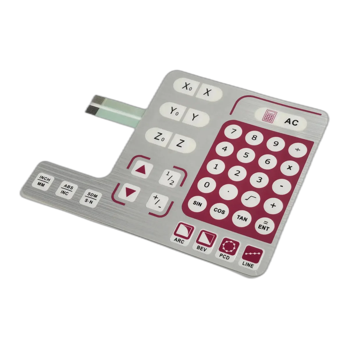
Build the key map around the operator's shift
The key construction follows the task hierarchy. Routine adjustments, mode changes, recovery actions, and safety functions should not look or feel interchangeable simply because they fit on one artwork file.
Routine navigation
Menu movement, numeric entry, speed or setpoint changes, and status review can use a repeated key family with consistent spacing and feedback.
Release input
Record press frequency, glove type, key pitch, force preference, labels, software response, and whether visual or audible confirmation is available.
Setup and mode changes
Recipe selection, manual or automatic mode, calibration, and changeover controls need a visible boundary from normal production input.
Release input
Use grouping, spacing, color, shape, hold time, software confirmation, or protected access as defined by the machine control strategy.
Fault recovery and reset
Reset, acknowledge, clear, and jog actions can carry different consequences even when the operator performs them during the same stoppage.
Release input
Define permissives, feedback, accidental-press prevention, and the relationship between the membrane key input, PLC logic, indicators, and physical machine state.
Safety-related functions
A printed red key can support interface labeling, but it does not become a safety-rated emergency-stop, guard, or interlock device by appearance.
Release input
The machine builder selects compliant safety hardware and validates the complete safety function, circuit, software, installation, and applicable machinery requirements.
Specify each factory load instead of writing harsh environment
Material and sealing decisions become useful only when the drawing names the substance, contact zone, duration, frequency, temperature, cleaning method, and acceptance result. One generic resistance claim cannot cover every factory fluid or maintenance practice.
No generic resistance claim replaces a named project exposure.
Oil, grease, and coolant
Name each fluid, concentration or formulation, temperature, dwell, wiping method, and face or edge contact zone.
Approve overlay appearance, print, windows, adhesive edges, key feel, and electrical function after the project sequence.
Cleaners and process chemicals
List cleaner, disinfectant, detergent, solvent, treatment chemical, rinse, mixed-use restriction, and contacts per shift.
Expose production-intent material and installed samples; record color, gloss, haze, swelling, bond movement, and function.
Dust, powder, and metal fines
Describe particle type, size range if known, airborne or packed exposure, static behavior, cleaning, and access to seams or keys.
Review edge geometry, emboss transitions, windows, enclosure gaps, venting, and cleaning access rather than assuming a flat face closes the cabinet.
Water and condensation
Define wiping, splash, spray, washdown, humidity, condensation, mounting angle, runoff, powered state, and recovery.
Test the complete installed boundary through face, perimeter, openings, tail slot, connector, enclosure joint, and drainage path.
Abrasion and mechanical contact
Identify gloves, fingernails, tools, labels, cleaning media, product contact, press count target, and accidental scraping zones.
Release hard coat, texture, print location, emboss geometry, window finish, and acceptance limits for wear and readability.
Temperature and vibration
Provide operating, storage, cycling, dwell, mounting, vibration source, cable mass, and enclosure deflection inputs.
Inspect bond, registration, tactile consistency, tail restraint, connector retention, appearance, and function after the defined combined sequence.
The panel, adhesive, and cable route are one assembly
Most field problems begin outside the printed key area. Paint texture, panel warp, narrow adhesive land, a sharp tail bend, or a connector trapped behind a door can undo an otherwise correct switch stack.
- Panel material and finish
Release metal, plastic, paint, powder coat, texture, curvature, contamination limit, and any primer or surface-preparation process. Adhesive selection is tied to that production surface.
- Flatness and support
Define datums, allowable warp, ribs, cutouts, fasteners, gasket load, and the support beneath every key. Unsupported areas can change feel and encourage edge movement.
- Adhesive land and openings
Keep a continuous usable bond area around the perimeter and each display, LED, fastener, or cutout. The drawing should show where liquid, dust, and cleaning pressure can reach.
- Tail exit and bend route
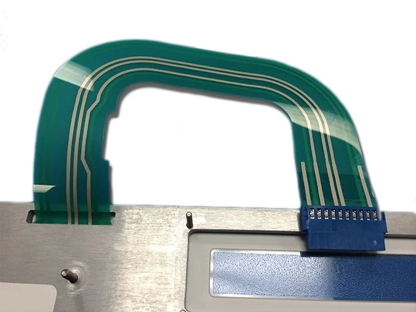
Set exit location, slot, stiffener, minimum project bend, moving or static zones, abrasion protection, strain relief, and clearance through door travel or service access.
- Connector and maintenance space
Name the connector, mating half, keying, latch access, cable direction, shield termination, replacement sequence, and dry or protected zone. Service should not pull the laminate apart.
Make every visual and electrical signal unambiguous
Industrial panels are read in daylight, dim cabinets, flashing fault states, and noisy electrical environments. Printed graphics, LEDs, backlighting, shielding, grounding, software, and the machine state must be reviewed as one information path.
Legends and viewing
Define operator distance, angle, ambient light, type size, contrast, languages, wear zones, and the hierarchy between printed labels and screen text.
Installed checkApprove production print and the powered panel from the intended operating positions.
Indicators and backlighting
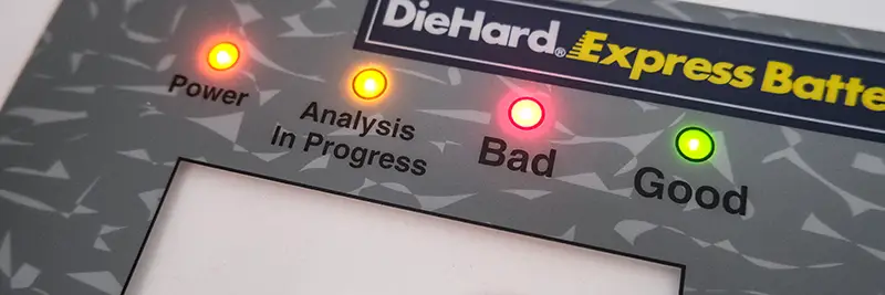
Define off-state concealment, on-state color, brightness, diffusion, masking, leakage, dimming, LED alignment, and the meaning of each state.
Installed checkReview matched off, normal, warning, and fault states in the assembled enclosure.
EMI, RFI, and ESD controls
Specify the system concern, affected circuit, shield type, conductive path, termination point, connector, enclosure bond, and test plan before adding a generic shield layer.
Installed checkMeasure the finished equipment to the OEM plan; component construction alone does not establish system compliance.
Grounding and electrical boundary
Assign protective earth, signal ground, shield ground, isolation, creepage, clearance, cable routing, and service responsibility at the system level.
Installed checkVerify the complete cabinet wiring and enclosure; JASPER can build the released interface details shown on its component drawing.
Qualify a production-intent panel before release
A loose membrane switch can confirm artwork and continuity. It cannot reproduce panel flatness, key support, hinge motion, cable strain, grounded metalwork, lighting, cleaning access, vibration, or the machine control response.
- 01
Freeze operating inputs
Record users, shifts, gloves, key tasks, exposure, lighting, mounting, service method, electrical interfaces, and equipment-level responsibility.
- 02
Build the intended stack
Use released overlay, circuit, domes or spacer, adhesive, panel finish, cutouts, tail, connector, shielding, hardware, and assembly process.
- 03
Run combined checks
Operate representative workflows, view all states, apply project exposure and handling sequences, service the cable route, and repeat visual and functional inspection.
- 04
Release evidence
Record the approved article, drawings, artwork, bill of materials, key map, inspection criteria, deviations, revision, and owners of machine-level validation.
What JASPER controls in interface production
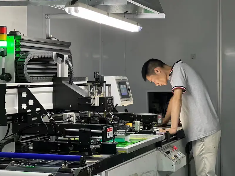
JASPER manufactures the released membrane switch or HMI component and records the checks named on the drawing and control plan. Useful production evidence is specific to the approved revision instead of a blanket industrial-performance claim.
- Released inputs
- Artwork, circuit master, bill of materials, dimensions, key map, tail, connector, and approved sample.
- Process route
- Printing, circuit production, precision cutting, lamination, assembly, and project-defined handling.
- In-process checks
- Registration, print appearance, dimensions, continuity, dome or key placement, connector, and assembly condition where specified.
- Release records
- Visual, dimensional, functional, packing, labeling, and other agreed inspection evidence tied to the released revision.
The machine builder or system integrator remains responsible for the hazard analysis, safety architecture, emergency-stop and guard functions, control software, enclosure, wiring, EMC, electrical safety, environmental qualification, regulatory marking, installation, and validation of the finished equipment.
Choose the architecture after the machine inputs
Custom membrane switch
Project-specific keys, windows, circuits, tail, connector, adhesive, and inspection criteria for a low-profile operator panel.
Tactile membrane switch
Metal-dome feedback and raised key location for repeated operation, gloves, and control groups that need a distinct press.
PCB or FPC membrane switch
Dense routing, LEDs, components, shielding, controlled connectors, or rigid support behind the printed front.
Complete HMI assembly
Front interface, display, touch, bezel, carrier, PCB, cable, and hardware coordinated as one released module.
Send the machine interface package before tooling
A useful industrial quotation identifies the operator task, mounting assembly, exposure, electrical interfaces, and sample evidence. Early drawings are enough when open decisions are marked clearly.
Open Industrial Project Form- equipment type, operator roles, shifts, workflow, routine controls, setup, recovery, and service tasks
- front-panel and enclosure drawings with material, finish, flatness, openings, hardware, and support plane
- glove type, key spacing, tactile preference, force target, press frequency, legends, and control hierarchy
- oil, coolant, cleaner, chemical, dust, water, temperature, vibration, abrasion, and cleaning inputs
- display windows, LEDs, dead-front graphics, backlighting, viewing distance, angles, and machine states
- circuit, voltage or current inputs, shielding, grounding, tail exit, bend route, connector, and cable restraint
- prototype quantity, annual estimate, sample deadline, assembly owner, inspection records, and acceptance plan
Industrial Control Panel Membrane Switch FAQ
What type of membrane switch works best for an industrial control panel?
Choose from the operator task and enclosure, not the industrial label. A tactile membrane switch suits repeated input and glove location, a non-tactile panel suits smooth software-confirmed controls, a PCB or FPC build suits dense electronics, and a complete HMI suits projects that need the display, front, carrier, and cable released together.
Can an industrial membrane keypad be operated with gloves?
Yes, when key size, spacing, emboss, tactile force, overlay support, and feedback are selected with the actual glove. Approve the mounted keypad with the intended glove types and representative production, setup, and recovery actions rather than judging a loose dome sample by hand.
Can a membrane switch resist oil, coolant, cleaners, and factory chemicals?
A construction can be selected and tested for named substances, but there is no universal chemical-resistant membrane switch. Provide each fluid or cleaner, concentration, temperature, dwell, contact zone, wiping method, and frequency, then define appearance, adhesion, tactile, optical, and electrical acceptance for the installed sample.
How is a membrane switch bonded to painted metal or textured plastic?
The adhesive is selected after the OEM defines the production substrate, paint or powder coat, texture, flatness, curvature, contamination limit, surface preparation, bond area, assembly pressure, and exposure. A sample should use the same finish and geometry because a generic flat test coupon does not represent the cabinet.
Can JASPER add EMI, RFI, or ESD shielding to an industrial membrane switch?
Shielding can be included when the drawing defines the system concern, conductive layer, termination, connector, enclosure bond, and grounding scheme. The equipment OEM or integrator verifies EMC and ESD performance on the complete wired machine; a shield layer by itself does not establish system compliance.
Can a printed membrane key serve as the machine emergency stop?
A printed key can label or request a control action, but appearance does not make it a safety-rated emergency-stop, guard, or interlock device. The machine builder selects the required safety hardware and validates the complete function, circuit, software, installation, risk reduction, and applicable machinery requirements.