
Choose membrane switch materials by the real wear, cleaning, UV, temperature, and mounting conditions of the product—not by a generic “PET or PC” catalog line. Specify overlay grade and finish, circuit film and ink system, spacer and dome path, and membrane switch adhesive materials against the enclosure substrate; validate the full stack before tooling freezes screens and dies.
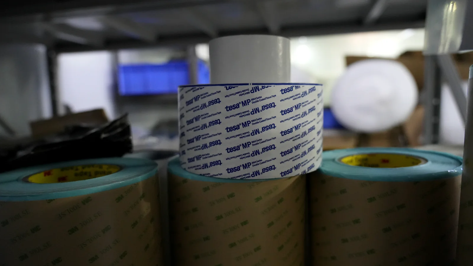
A membrane switch fails in the field more often from a mismatched bill of materials than from a missing icon on the artwork. The overlay film, hard coat, printed conductors, spacer, dome or contact method, rear adhesive, and support plate each answer a different stress. This guide is for OEM mechanical, electronics, and quality engineers who must release a custom membrane switch construction that still matches the enclosure after cleaning, flexing, and thermal cycling. Material selection remains tied to the actual enclosure, exposure, and acceptance plan.
1. Why membrane switch materials are an exposure decision
Membrane switch materials are not a single “best film.” They are a set of layer decisions that only make sense when the product’s operating exposure is written down. Indoor lab instruments, powder-coated industrial cabinets, wash-down food equipment, and sun-exposed outdoor housings do not share one default stack—even when the front legend looks similar.
Wrong materials show up late. A polycarbonate overlay that looks sharp at first article can haze or crack after aggressive cleaners. A rubber-based rear tape that peels on a low-surface-energy plastic does not “improve” with more pressure at assembly. Silver traces without a wear or migration strategy at contact pads can change resistance after humidity exposure. A tactile stack with no planned air path can feel different on the bench than on the sealed panel (trapped air changes tactile response and must be controlled by the vent path).
Tooling multiplies the cost of guessing. Overlay print masters, spacer dies, emboss tools, adhesive purchase, and inspection fixtures all lock when the drawing freezes. Changing the rear adhesive after first article can move overall thickness and bezel fit. Changing overlay polymer late can force a reprint and a new hard-coat process window. The practical test is simple: can Manufacturing, Quality, and the Enclosure Team describe the same stack, the same mounting surface, and the same environmental stresses from one controlled package?
This article turns that test into eight evaluation criteria, a step-by-step selection process, release blockers that should stop a quote comparison, and a short RFQ package focused on environment and enclosure substrate.
| Exposure the product actually sees | Material decision that absorbs it first | Typical late failure if ignored |
|---|---|---|
| Finger abrasion, keys, gloves | Overlay grade + hard coat | Scratched legends, worn dead-front |
| Alcohols, detergents, oils | Overlay chemistry + ink system | Haze, ink attack, edge whitening |
| UV / outdoor light | UV-capable film grade + finish | Yellowing, embrittlement |
| Heat / cold cycling | Film dimensional stability + adhesive chemistry | Curl, lift, open circuits at flex |
| Humidity / condensation | Conductor protection + vent / seal concept | Resistance drift, intermittent keys |
| Mounting substrate energy | Rear adhesive family | Edge lift, partial bond |
| Enclosure stiffness / openings | Backing, support, seal path | Mushy keys, false “IP” claims |
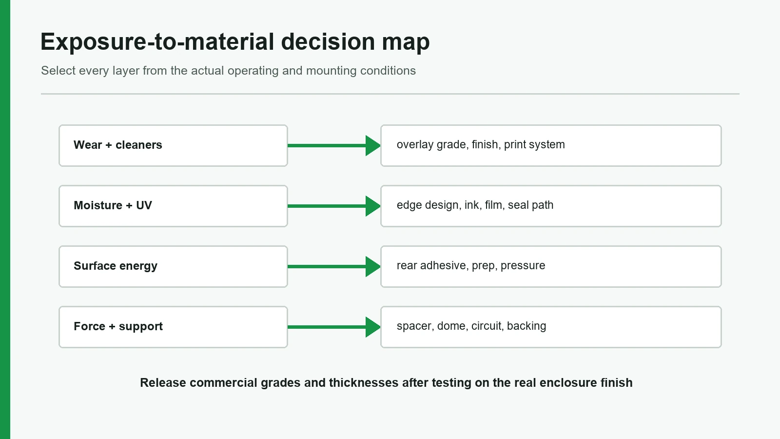
2. The 8-point membrane switch materials framework
Treat each criterion as a release item. A is evidence the package can proceed. A is a reason to hold tooling even if the front art looks finished.
2.1 Define operating exposure before naming polymers
Write the environment before the acronyms. Record indoor vs outdoor, UV exposure, cleaning chemicals and frequency, temperature range of interest, humidity or condensation risk, operator gloves, expected key force and life class, and whether the panel is wash-down, coastal, or chemical-splash. Without that list, suppliers invent different stacks under one part number.
One exposure paragraph on the drawing or RFQ that names cleaners, temperature interest, UV/outdoor status, and mounting surface finish.
“Industrial grade materials” with no chemicals, no temperature interest, and no substrate callout.
2.2 Overlay film: polyester membrane switch vs polycarbonate overlay
The graphic overlay is the user-facing film. A polyester membrane switch overlay (PET family) is the common default for keypads that must survive flexing at embossed keys and many cleaning environments. A polycarbonate overlay (PC family) is often chosen for print appearance, clarity in windows, and forming behavior on some emboss geometries. Neither acronym is a specification. Covestro’s film-selector materials for graphic and membrane applications emphasize grade, surface finish, and functional variants—not “PET” or “PC” alone.
| Decision | Prefer PET-family overlay when… | Prefer PC-family overlay when… | Prefer neither default when… |
|---|---|---|---|
| Flex at keys | High flex / repeated emboss life is critical | Mild flex, appearance dominates | Extreme outdoor UV without verified grade |
| Chemicals | Frequent alcohols / detergents / many industrial cleaners | Mild indoor cleaners only | Aggressive solvents not listed on any candidate TDS |
| Optics / forming | Matte hard-coated industrial look is enough | Clear windows, deep form, specific PC finish | Optical stack needs glass or acrylic capacitive cover instead |
| Cost / process | Standard printed second-surface keypad | Special emboss / texture package justified | Product should move to silicone keypad or capacitive panel |
Hard-coated polyester families marketed for membrane graphics (for example Autotex-type products from MacDermid Autotype) and polycarbonate film families (for example Makrofol- or Lexan-type lines) only become comparable when grade, thickness, finish, and print side are named. In RFQ planning conversations, PET overlays commonly land in about 0.125–0.250 mm (often 0.150–0.188 mm), and PC overlays often land in about 0.175–0.250 mm—treat those as industry-typical starting bands, then lock the commercial grade TDS before tooling.
When PET is not the best choice: deep emboss or optical requirements that a qualified PC grade handles better, and chemical/UV exposure is mild enough for that grade.
When PC is not the best choice: aggressive cleaners, high flex life at keys, or outdoor UV without a verified hard-coat / UV-capable construction.
Overlay line lists polymer family, grade or commercial film name, thickness, finish (gloss/matte/textured), hard-coat intent, and second-surface print.
“PET or PC, supplier choice” on a drawing headed for tooling.
2.3 Hard coat, print system, and windows
The hard coat and print system decide scratch resistance, chemical resistance, and whether windows stay clear. Second-surface printing protects color under the film; first-surface decoration needs a different durability story. Display and LED windows need defined transparency, color, and dead-front behavior. Related graphic overlays for non-switch panels follow the same grade and finish discipline.
Do not treat “hard coat” as a binary checkbox. Ask what pencil hardness or abrasion method the film supplier documents, which cleaners are listed, and whether embossed keys keep the coat intact. Where film TDS files use ASTM D3363 pencil hardness, industrial hard-coated overlays are often discussed at about ≥3H as a planning target—not a universal pass/fail for every grade. Windows cut into the overlay need edge quality and adhesive keep-out so the display does not see glue bloom.
Print side, hard-coat callout, window list with optical intent, and cleaner list aligned to film TDS language.
Full-color first-surface art on an uncoated film in a high-abrasion or chemical area with no protective strategy.
2.4 Circuit substrate and conductive ink system
Most flexible membrane circuits use PET circuit film with printed silver, carbon, or silver-plus-carbon constructions. Circuit PET is commonly planned around 0.075–0.175 mm, with many keypad circuits near 0.100–0.125 mm; heat-stabilized grades appear when temperature interest rises (industry-typical band—verify). FPC copper tails appear when bend radius, current, or connector strategy requires them. Ink choice covers more than conductivity alone: contact pads see mechanical wear; humidity can stress silver constructions; carbon is often used for durability or contact finishing even when silver carries the traces.
Released limits stay grade-specific. Sheet resistance, cure schedule, and migration behavior belong to the ink TDS and the manufacturer’s process window—not to a blog table of universal ohms. What the drawing must freeze is technology (printed silver / carbon / hybrid / FPC), pad finish strategy, dielectric or coverlay concept, and tail construction.
Circuit technology named, pad construction described, dielectric/cover intent stated, tail type and stiffener concept shown.
“Conductive ink as required” with no pad wear strategy and no tail definition.
2.5 Spacer, dome or contact method, and air path
Spacer thickness and opening geometry set travel and isolation before actuation. Spacer films are often planned from about 0.05–0.25 mm depending on dome height and desired travel (industry-typical band—verify). Metal domes, poly domes, or non-tactile shorting pads change force, sound, and life class. Force is series-specific; many OEM RFQs still discuss metal-dome actuation in a rough 1–4 N (about 100–400 gf) conversation range before a named dome series freezes the real curve—do not treat that band as a life or feel guarantee. Support under the dome (rigid plate, PCB, or adequate enclosure land) is part of the material stack even when the BOM line only says “dome.”
If the keypad is tactile, plan how air moves when the dome collapses. Metal-dome venting design treats trapped air as a factor in tactile response and routes venting through spacer, carrier, or board depending on the stack. A fully sealed cavity with no defined path can be the wrong construction for consistent feel—even when the front graphic is perfect.
Spacer material/thickness, opening map, dome or non-tactile method, support concept, and vent philosophy if tactile.
Tactile force target with no dome series, no support callout, and no air-path note.
2.6 Membrane switch adhesive materials vs enclosure substrate
Membrane switch adhesive materials decide whether the assembly stays on the enclosure after temperature and cleaning. High-surface-energy metals and many plastics may suit acrylic transfer constructions such as 3M 467MP (200MP acrylic, positioned by 3M for metals and high-surface-energy plastics; transfer thickness commonly cited near 0.05 mm / 2 mil on the product family). Where more gap fill is needed, related acrylic transfers such as 3M 468MP are often discussed near 0.13 mm / 5 mil. Many powder coats, textured paints, and low-surface-energy plastics need LSE-capable constructions such as 3M 9495LE (300LSE, positioned by 3M for many LSE plastics and powder-coated paints). These are examples, not universal defaults: exact thickness, liner, and process still follow the selected TDS and the real enclosure finish.
Adhesive surface preparation requires clean, dry, unified surfaces and firm application pressure. Skipping surface energy and finish details is how “the adhesive failed” tickets get written when the real issue was powder texture or residual mold release.
When 467MP-class HSE acrylic is not the best choice: LSE plastics, many powder coats, heavy texture, or applications that need a different carrier/thickness family after substrate testing.
When a generic “double-sided tape” line is never enough: any production RFQ—chemistry and thickness must be named.
Rear adhesive listed by family or commercial designation, thickness, and substrate (material + finish + texture).
“3M or equivalent” with no series, no thickness, and no mounting surface description.
2.7 Backing, support, stiffener, and connector interface
Rear materials go beyond adhesive alone. Rigidizers, aluminum or FR-4 backers, gasket features, EMI shields, and tail stiffeners change height, feel, and assembly. Connector choice controls flex thickness, contact side, pitch, and actuator style; FPC connector drawings show how those attributes live on the connector drawing, not on a freehand tail sketch.
If the enclosure is thin or open behind the keys, a soft stack will feel soft no matter how expensive the overlay is. If the tail exit fights the gasket land, sealing claims collapse at the first enclosure test.
Support plate or enclosure land defined, stiffener length/thickness, connector P/N or full mating spec, tail exit owned on the assembly drawing.
Flexible circuit floating over a large unsupported cutout with a tactile force requirement.
2.8 Validation package: samples prove the stack, not the brochure
Materials claims close only when samples are built from production-intent materials and tested against the exposure list. Visual approval of a front graphic is not adhesive approval. Continuity on a flat bench is not continuity after mounting and thermal cycling. If the program claims enclosure protection, frame the test article under IEC 60529 as an enclosure classification—not as a free-floating property of a loose switch.
Route validation work through a controlled quality and testing plan: what is measured on first article, what is lot-checked, and what is application-level only.
Sample BOM matches production intent; acceptance covers visual, dimensional, electrical, tactile, adhesive fit, and agreed environmental checks.
Marketing materials list with no sample matrix and no owner for environmental tests.
Full-stack reference (text diagram)
Operator face
Graphic overlay (PET- or PC-family grade + finish + hard coat)
Second-surface inks / windows / dead-front features
Overlay adhesive
Optional dome retainer / metal or poly dome
Upper circuit (if used) — PET film + Ag/C inks or FPC
Spacer with key openings (+ vent concept if tactile)
Lower circuit
Rear adhesive / gasket features ← match enclosure substrate
Backer / EMI shield / enclosure mounting land
Tail exit → stiffener → connector (drawing-controlled)
| Layer | Function | Common material families (examples) | Typical industry thickness / value band (verify) | Freeze on the drawing |
|---|---|---|---|---|
| Overlay | Wear face, graphics, windows | PET hard-coated films; PC graphic films | PET often 0.125–0.250 mm (common 0.150–0.188 mm); PC often 0.175–0.250 mm | Grade, thickness, finish, print side |
| Overlay adhesive | Bond overlay to circuit/spacer | Acrylic PSA transfer / double-coated | Often ~0.025–0.13 mm class | Thickness, series if controlled |
| Circuit | Conductive paths | PET + silver/carbon inks; FPC copper | Circuit PET often 0.075–0.175 mm (common 0.100–0.125 mm) | Technology, pad finish, dielectric |
| Spacer | Isolation / travel | PET or adhesive spacer films | Often ~0.05–0.25 mm with dome/travel | Thickness, openings, vent |
| Tactile element | Force / click | Metal dome, poly dome, or non-tactile | Force often discussed ~1–4 N (100–400 gf) before series lock | Series/method + support |
| Rear adhesive | Mount to enclosure | HSE acrylic (e.g. 467MP-class ~0.05 mm); thicker acrylics (e.g. 468MP-class ~0.13 mm); LSE (e.g. 9495LE-class) | Chemistry + thickness vs substrate | Series, thickness, substrate |
| Backer / gasket | Support, seal, EMI | Al / FR-4 / PET stiffener; gasket materials | Driven by stack height and land design | Stack height, lands, openings |
| Tail / connector | Electrical exit | PET tail, FPC, ZIF/FPC connector families | Flex thickness per connector drawing | P/N or full mating dimensions |
Industry-typical starting values (planning bands, not guarantees)
The numbers above are industry-typical planning bands used to stop RFQs from saying only “PET + tape.” These bands are not universal limits. Before tooling, lock each one to a commercial designation and the selected material data sheet. Temperature interest is likewise program-defined: many indoor instruments are discussed near room ambient (about 15–30 °C); many industrial panels are discussed with interest bands such as −20 to +70 °C or −40 to +85 °C. Write the product’s numbers—do not copy a band onto every film line.
| Planning question | Industry-typical starting discussion | What still must be verified |
|---|---|---|
| Overlay thickness | 0.125–0.250 mm class | Grade, hard coat, emboss, chemical list |
| Circuit film thickness | 0.100–0.125 mm common on PET circuits | Cure, bend, temperature interest |
| Rear adhesive on metal / HSE plastic | 467MP-class acrylic transfer (~0.05 mm) as a common example | Real surface energy, oil, texture |
| Rear adhesive on powder coat / LSE plastic | 9495LE-class or other LSE construction | Bond trial on the actual finish |
| Need more gap fill on HSE surfaces | 468MP-class thicker acrylic transfer (~0.13 mm) as a common example | Bezel height budget |
| Hard-coat durability language | ASTM D3363 pencil hardness when the film TDS uses it; ≥3H often discussed | Cleaner list + emboss retention |
| Tactile force language | ~1–4 N conversation range until a dome series is named | Support plate, spacer, vent |
| Outdoor / UV language | Name a weathering method (e.g. ASTM G154 / G155 family), not “UV OK” | Hours + acceptance on the finished stack |
3. Step-by-step: from environment notes to released materials
Step 1 — Capture environment and enclosure substrate
List cleaners, UV/outdoor status, temperature interest, humidity, operator conditions, and the mounting surface (metal, ABS, PC, powder coat, texture, paint system). Photograph or call out textured and low-energy surfaces. This is the CTA package in practical form: share the environment and enclosure substrate before asking for a final BOM.
Step 2 — initial the full layer stack, not just the overlay
Build the text stack in §2. Assign PET- or PC-family intent, circuit technology, tactile method, rear adhesive class, and support. If height is constrained, put a maximum stack-up on the drawing so adhesive and dome choices cannot silently grow.
Step 3 — Convert acronyms into commercial grades
Replace “PET” with a grade or approved-equivalent family. Replace “adhesive” with a series and thickness class. Replace “silver ink” with a technology description and pad strategy. Use supplier TDS language for cleaners and temperature—not sales adjectives.
Step 4 — Align adhesive to substrate tests
If the enclosure is powder-coated or LSE plastic, do not assume HSE acrylic transfer will hold. Run a simple bond evaluation on the real finish after the surface prep the adhesive supplier documents (clean, dry, unified, firm pressure). Record peel or lift observations against the program’s acceptance idea.
Step 5 — Build production-intent samples
Samples must use the intended overlay grade, ink system, adhesive, and support—not a random lab leftover. Mount at least one sample on a representative enclosure coupon. Check actuation, continuity, tail bend, window fit, and edge lift after handling that resembles assembly.
Step 6 — Run the exposure checks that match the RFQ
Pick tests from the exposure list: cleaner wipe protocols, thermal cycling of interest, humidity storage, UV only if outdoor is real, and enclosure-level ingress only if the claim is enclosure-level under IEC 60529. Hold tooling if results force a polymer or adhesive change.
Step 7 — Freeze the controlled materials list
Release a materials schedule with revision control: overlay, adhesives, circuit construction, dome/contact, backer, connector. Point quotes at that revision so “equivalent” substitutions need engineering sign-off.
4. Exposure → material decision matrix
| Dominant exposure | Overlay direction | Circuit / contact direction | Adhesive / seal direction | Validation focus |
|---|---|---|---|---|
| High key abrasion, indoor | Hard-coated PET-family often first | Pad wear strategy (carbon finish or qualified silver) | Match substrate energy | Abrasion + actuation life class |
| Frequent alcohol / detergent wipe | PET-family + cleaner-listed hard coat | Dielectric integrity after wipe | Acrylic chemistry per TDS | Cleaner soak/wipe on finished sample |
| Outdoor UV | Only UV-capable grades; verify finish | Avoid unproven outdoor ink assumptions | UV + thermal capable PSA | Weathering method agreed in RFQ |
| Wide temperature swing | Dimensionally stable film grades | Flex tails rated for bend + temp | Acrylic transfer common; verify low-temp tack | Thermal cycle on mounted sample |
| Powder coat / LSE plastic mount | Independent of overlay choice | Independent | LSE-capable family (e.g. 9495LE-class) often needed | Bond test on real finish |
| Wash-down / claimed ingress | Overlay + perimeter design together | Protect circuit edges | Gasket + adhesive land design | Enclosure test article (IEC 60529) |
| Strong tactile through gloves | Overlay emboss compatible with force | Metal dome + rigid support | Adhesive must not creep into openings | Force/travel + support check |
Test methods often named with the materials package
Use the exposure list to pick methods; freeze hours, cycles, and acceptance on the program—do not invent a universal outdoor life from a method name alone.
| Stress to prove | Method families commonly named in RFQs | Notes for membrane materials |
|---|---|---|
| UV / weathering | ASTM G154, ASTM G155, ASTM D4329 | Specify cycle, hours, and optical/mechanical acceptance on the finished stack when outdoor is real |
| Salt fog | ASTM B117 | Hours are program-defined; useful for coastal / road-salt discussion |
| Steady damp heat | IEC 60068-2-78 | Example discussion point: elevated temp + high RH duration—write the product profile |
| Cyclic damp heat | IEC 60068-2-30 | Use when condensation cycling matters |
| Temperature change | IEC 60068-2-14 | Pair with adhesive + flex-tail checks on a mounted sample |
| Surface hardness language | ASTM D3363 (pencil) when film TDS uses it | Complements, does not replace, chemical wipe tests |
| Enclosure ingress claim | IEC 60529 | Test article is the enclosure assembly, not a loose switch label |
5. Release blockers that disqualify a materials package
- Overlay listed only as “PET” or “PC” with no grade, thickness, or finish.
- Polycarbonate overlay specified into heavy chemical or outdoor UV use without a verified grade and hard-coat story.
- Adhesive listed as “double-sided tape” or “3M or equal” without series, thickness, or substrate.
- HSE acrylic assumed on powder coat / LSE plastic with no bond evaluation.
- Tactile stack with no support and no air-path concept while force and feel are guaranteed on paper.
- IP65/IP67 claimed on a loose switch without enclosure test article framing under IEC 60529.
- Sample approved on non-production films or adhesives—approval does not transfer.
- Connector and tail undefined while the membrane is “final.”
- Universal life or outdoor year claims with no test method or construction revision.
- Materials “selected by the supplier after purchase order” on a tooling-release drawing.
6. Project input checklist (environment + enclosure substrate)
Send this package with the drawing when requesting a materials recommendation or engineering review:
- Product use environment (indoor/outdoor, UV, dust, moisture).
- Cleaning chemicals and method (wipe, spray, immersion—if any).
- Temperature interest (storage and operation, even if approximate).
- Operator conditions (gloves, force preference, key hierarchy).
- Enclosure material, finish, texture, and flatness in the bond area.
- Maximum stack height and bezel or window constraints.
- Tactile vs non-tactile intent; noise limits if any.
- Tail exit, connector preference or mating constraints.
- Sealing claim level (none / gasket / enclosure-tested).
- What first-article tests will accept or reject the stack.
7. Frequently asked questions
What are the main membrane switch materials in a typical stack?
A typical flexible stack uses a graphic overlay (PET- or PC-family film), overlay adhesive, printed circuit film with silver and/or carbon inks, a spacer, optional metal or poly domes, rear adhesive, and often a stiffener or backer at the tail. Industry-typical planning bands often put overlays near 0.125–0.250 mm and circuit PET near 0.100–0.125 mm, but exact grades and TDS windows must follow exposure and enclosure substrate—not a single catalog default.
Is polyester or polycarbonate better for a membrane switch overlay?
Neither is universally better. Polyester membrane switch overlays are the common default for flex life and many cleaning environments. Polycarbonate overlays are often chosen for appearance, clarity, and some forming needs. Choose by grade, hard coat, cleaners, UV, and emboss—not by polymer acronym alone.
What should I specify for membrane switch adhesive materials?
Name the adhesive family or commercial designation, thickness, and the enclosure substrate (material + finish + texture). Examples include 3M 467MP-class acrylics for many metals and high-surface-energy plastics, and 3M 9495LE-class constructions for many LSE plastics and powder coats. Confirm with surface prep and a bond check on the real finish.
Can I assign IP65 or IP67 to the membrane switch alone?
Not as a complete claim. IEC 60529 classifies protection for enclosures of electrical equipment. Ingress performance depends on the enclosure, gasket, openings, and test article—not on a loose keypad label.
Do I need a hard coat on every overlay?
Most production keypads need a defined surface finish and hard-coat strategy if keys see abrasion or chemical wipe-down. The coat and film grade should appear on the BOM; “hard coat optional” without exposure notes is incomplete.
When is a polycarbonate overlay the wrong choice?
When aggressive cleaners, high flex at embossed keys, or outdoor UV dominate and no verified PC grade/hard-coat package is offered. In those programs a qualified PET-family overlay is usually the safer starting point.
When is the default polyester construction the wrong choice?
When the product needs PC-specific optical or forming behavior, chemical exposure is mild, and a named PC grade with finish data is available. Also reconsider pure membrane construction if the HMI really needs silicone keypad travel or a capacitive glass/acrylic surface.
How should samples be approved for materials?
Approve a production-intent stack mounted on a representative substrate. Include visual, dimensional, electrical, tactile, adhesive fit, and any environmental checks named in the RFQ. Do not treat a front-graphic proof as full materials approval.
Which details belong in the RFQ materials section?
Environment and cleaners, temperature interest, overlay grade/finish intent, circuit technology, dome/contact method, rear adhesive class, enclosure substrate, stack height limit, connector/tail constraints, and the tests that will accept first article.
Who should review the materials package before tooling?
The OEM mechanical owner, electronics owner, quality owner, and the membrane manufacturer’s engineering team should agree on one controlled stack. JASPER can review drawings and environment notes as one manufacturer option; the same checklist applies to any qualified supplier.
8. What to do next
If a membrane switch drawing is approaching tooling, stop treating materials as a footnote under the color callouts. Send the environment list, enclosure substrate details, stack height limit, and current layer assumptions with the drawing. Ask for a controlled materials schedule—overlay grade, ink system, spacer and dome path, and membrane switch adhesive materials matched to the real mounting surface—before screens and dies freeze.
Technical References
- Source: 3M 467MP 200MP adhesive transfer tape technical data. Accessed 2026.
- Source: 3M 9495LE 300LSE double-coated tape technical data. Accessed 2026.
- Source: 3M surface preparation and bonding guidance. Accessed 2026.
- Source: Covestro Makrofol and Bayfol Film Selector Guide. Accessed 2026.
- Source: MacDermid Autotype hard-coated interface film product guidance. Accessed 2026.
- Source: Snaptron metal dome venting guidance. Accessed 2026.
- Source: TE Connectivity FPC connector product drawings. Accessed 2026.
- Source: IEC 60529 enclosure protection classification. Accessed 2026.
- Source: IEC 60068 environmental testing method series. Accessed 2026.
- Source: ASTM D3363 film hardness by pencil test method. Accessed 2026.
- Source: ASTM D3330 pressure-sensitive tape peel adhesion test method. Accessed 2026.
- Source: IEC 61000-4-2 electrostatic discharge immunity testing. Accessed 2026.
- Source: RoHS Directive 2011/65/EU restricted substances scope. Accessed 2026.
Select materials from the actual exposure
Send the cleaners, temperature range, UV and moisture exposure, mounting substrate, finish, stack limit, and approval tests.