
Stack and condition review
Confirm active files, materials, liners, orientation, cleanliness, storage, conditioning, adhesive, domes, components, PCB, display, cables, backer, and supplied parts.
JASPER laminates printed overlays, spacers, circuits, adhesives, domes, LEDs, backers, gaskets, PCBs, display windows, cables, and related interface parts according to a released stack and assembly sequence. The plan must control alignment, pressure, contamination, trapped air, exposed adhesive, tail routing, connectors, and protection.
A clean overlay, working circuit, correct adhesive, and approved PCB do not guarantee a good HMI after stacking. Alignment, sequence, pressure, surface condition, dome or LED placement, tail routing, connector work, backer flatness, windows, support, and packaging can create new defects. JASPER defines the assembly boundary and places checks where the interface risk is created.
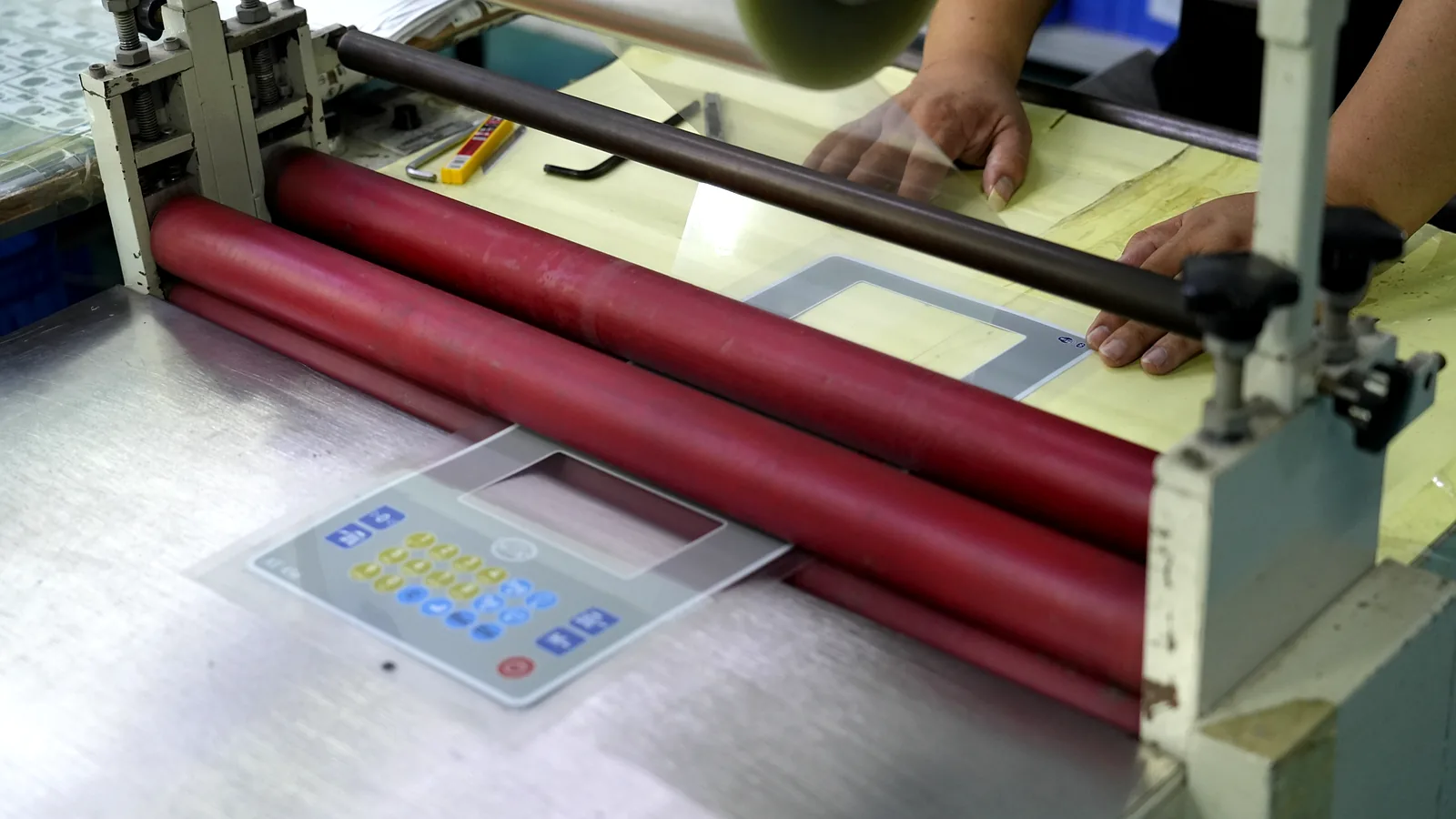
The exact route varies by overlay, membrane switch, keypad, touch sensor, PCB, display, backer, and enclosure scope.
Confirm active files, materials, liners, orientation, cleanliness, storage, conditioning, adhesive, domes, components, PCB, display, cables, backer, and supplied parts.
Use released datums and sequence for print, spacer, circuit, dome, LED, adhesive, gasket, backer, PCB, windows, tails, connectors, and protection.
Inspect alignment, particles, bubbles, folds, adhesive, surface, dome/component position, continuity, isolation, LEDs, cables, and hidden features before closure.
Review appearance, dimensions, key or touch input, lighting, connector, fit, labels, quantity, protection, packaging, records, deviations, and active revision.
Final inspection is not an efficient substitute for staged evidence before a layer or housing hides the defect.
| Assembly interface | Controls to define | Typical hidden risk |
|---|---|---|
| Overlay, spacer and circuit | Datums, key/window position, vents, dome pockets, adhesive land, liner removal, pressure, surface and alignment checks | Poor key response, clipped window, trapped air, contamination or exposed adhesive |
| Domes, LEDs and components | Part identity, orientation, placement, retention, solder/attachment boundary, intermediate electrical and visual checks | Moved dome, reversed LED, damaged trace, hidden contamination or intermittent function |
| Tail, cable and connector | Exit, bend, stiffener, pinout, strain relief, cable route, connector work, mating check and protection | Pin mismatch, cracked conductor, cable pinch, pullout or assembly interference |
| Backer, PCB, display and enclosure | Flatness, fasteners, spacers, windows, grounding, support, gasket, service access, fit, torque and installed test | Warp, optical misalignment, poor support, shorting, seal gap or service rework |
State what JASPER supplies, what the customer supplies, what arrives programmed, and which party owns the finished-system check.
Depending on the quote, scope can include overlays, membrane or touch inputs, spacers, adhesives, domes, LEDs, backers, gaskets, PCBs, displays, cables, connectors, fasteners, labels, protection, inspection, and packaging.
They can be reviewed when supply responsibility, incoming condition, revision, programming state, handling, storage, yield ownership, alternates, test, rework, and shortage rules are explicit.
The project route can define material conditioning, cleaning, protected surfaces, staged liner removal, alignment, pressure, operator handling, environmental controls, in-process inspection, acceptance zones, and rework rules.
Approve a production-intent configuration after fit, appearance, key or touch behavior, optics, cables, connector, electrical function, mounting, labels, packaging, records, and open system responsibilities are reviewed.
Send the exploded stack, BOM, supplied parts, PCB/display/cable interfaces, quantities, and acceptance plan for review.
Share the project basics. JASPER will review the stack, materials, connector, quantity, and production risks.