
Electrode geometry
ControlRelease the active shape, keep-outs, connection point, orientation, and relation to the printed icon.
Failure modeThe visible command and effective sensing area do not remain aligned.
A capacitive touch switch is a fixed command area with no moving key travel. Reliable operation depends on the electrode, cover stack, spacing, routing, feedback, controller boundary, neighboring conductive parts, and the states in which a touch must be accepted or ignored.
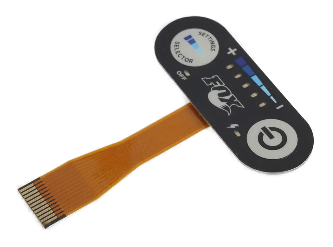
A capacitive touch switch detects a field change at one defined electrode and reports a discrete input to the controller or host. Each printed area has a fixed identity and command boundary.
The printed icon does not create the switch. The released construction must connect that icon to the electrode geometry, cover layers, spacing from other channels, trace route, reference conditions, controller settings, and nearby conductive structure.
Use this route when separate commands such as power, start, stop, mode, acknowledge, or selection need a sealed flat surface. Use the keypad route when many channels require a shared map, simultaneous-input rules, or slider and wheel behavior.
Most field problems begin where the electrode drawing stops and the installed product begins.
Release the active shape, keep-outs, connection point, orientation, and relation to the printed icon.
Failure modeThe visible command and effective sensing area do not remain aligned.
Identify every decorative, printed, bonded, coated, and unsupported region above the electrode.
Failure modeA sample tuned under one surface is reused under a different field path.
Map neighboring channels, bezels, displays, fasteners, brackets, shields, and grounded or floating parts.
Failure modeA nearby finger or conductive feature influences the wrong channel.
Control trace paths, crossings, connector assignment, returns, guards, reference strategy, and test access.
Failure modeThe route behaves like part of the electrode or couples into another input.
Define acknowledgment plus behavior for moisture, cleaning, held contact, palm contact, blocked commands, and faults.
Failure modeThe operator sees acceptance when the host rejected the command, or a surface event becomes an action.
Name who owns controller choice, tuning files, filtering, wake behavior, firmware changes, event logging, and final validation.
Failure modeA panel revision and a controller revision are changed independently without retesting.
The drawing and state table should let panel, electronics, firmware, enclosure, and validation teams reproduce the same command behavior.
| Decision | Options to Review | Release Question |
|---|---|---|
| Switch function | Momentary request, maintained state request, wake input, confirmation, interlock request, or project command | What event does the host receive, and when may it act? |
| Electrode and icon | Filled shape, ring, segmented area, guarded area, or project geometry | How are the printed target, active field, keep-out, and datum linked? |
| Cover path | Decorative sheet, glass, acrylic, printed film, adhesive zones, coatings, or mixed stack | Which released layers sit between the finger and electrode? |
| Channel separation | Pitch, ground or guard features, routing separation, metal keep-outs, and enclosure boundaries | How is neighboring influence checked in the installed assembly? |
| Controller interface | Remote controller, panel-mounted controller, customer board, digital event, raw channel, or project interface | Where do sensing ownership, tuning, filtering, and host logic begin and end? |
| State evidence | Intended touch, held touch, adjacent touch, moisture, cleaning, glove, blocked, wake, disconnect, and fault cases | Which response and feedback are correct for every named state? |
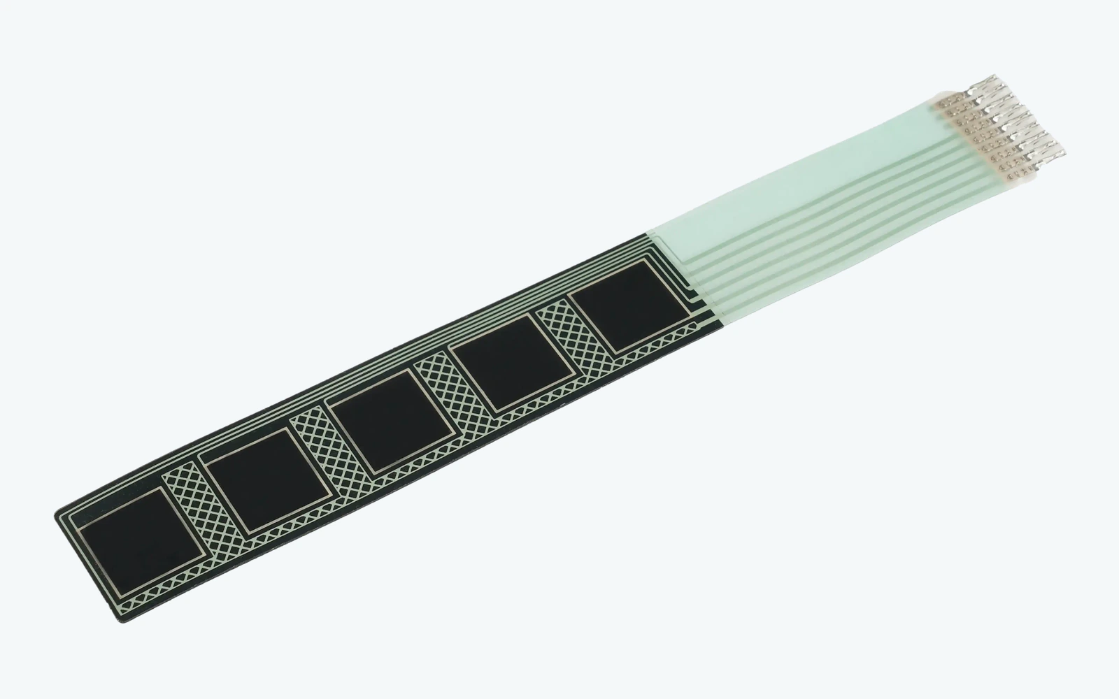
Bezels, display frames, fasteners, shields, brackets, wiring, and grounded or floating enclosure parts reshape the field around a discrete electrode. Their location and state belong in the sensing review.
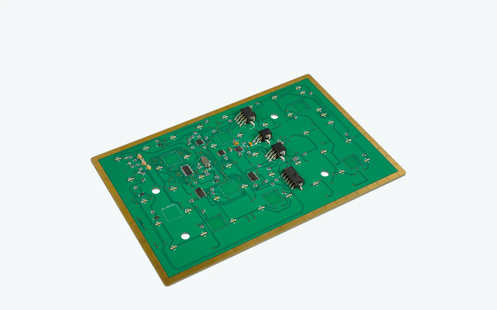
The controller may detect a field change while the host is asleep, busy, locked, faulted, or intentionally ignoring input. Feedback should identify whether the touch was merely detected, accepted as a command, or completed by the host.
List every switch function, accepted event, held behavior, blocked state, wake path, feedback, and host action.
Align icons, electrodes, cover layers, spacing, routing, adjacent metal, enclosure datums, and connector.
Define controller, tuning, filtering, firmware, event logging, panel test, and host-validation responsibilities.
Exercise intended, adjacent, gloved, wet, cleaning, held, blocked, wake, and fault cases in the real assembly.
Lock artwork, cover, circuit, enclosure, controller file, firmware baseline, inspection, and retuning triggers.
Check cover construction, electrode-to-icon registration, reference conditions, controller state, grounding, and host acceptance.
Review moisture and cleaning states, adjacent metal, palm or edge contact, routing coupling, wake logic, and event filtering.
Inspect electrode spacing, shared routes, guards, enclosure features, operator approach, and simultaneous contact.
Trace detection, controller event, host acceptance, command completion, and the exact indication shown at each stage.
These applications use separate no-travel commands whose installed field and host state can be validated.
Start, stop, mode, acknowledge, and setting commands on sealed equipment fronts.
Wipe-clean discrete controls with deliberate cleaning, disabled, and alarm-related states.
Power, program, option, and confirmation areas coordinated with icons and indicators.
Lighting, access, room, and equipment commands with clear active and blocked feedback.
Fixed console or panel commands reviewed around gloves, moisture, metal trim, and host interlocks.
Revision-controlled function keys around displays, connectors, chassis metal, and instrument firmware.
A marked front-panel image plus the enclosure and controller concept can expose the important sensing conflicts before circuit release.
It is a discrete no-travel sensing area that reports one defined command or state request through a controller to the host.
Compare how the manufacturer reviews electrode artwork, cover construction, spacing, routing, adjacent metal, controller ownership, false-touch states, installed samples, and linked revision control.
No. A touch switch represents one fixed command area with a released channel and host action. Touchscreen projects follow a different sensing and application route.
Investigate moisture or cleaning states, nearby conductive parts, crowded channels, routing coupling, grounding changes, enclosure revisions, wake behavior, and host filtering using the installed event trace.
It should prove icon alignment, intended and adjacent touch behavior, held and blocked states, feedback sequence, controller and host response, enclosure fit, and recovery from named surface conditions.
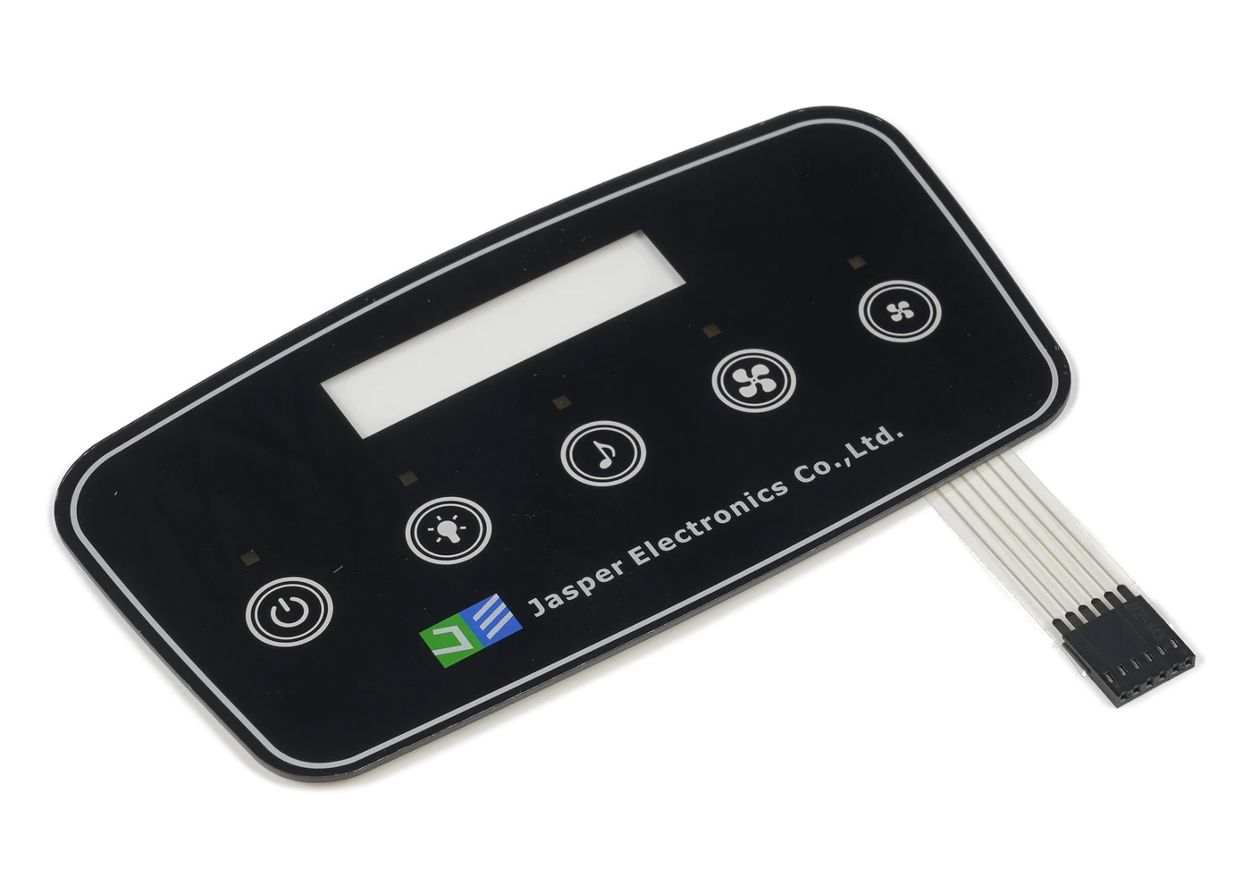
Return to the family comparison for keypad, PCAP, window, backlit, and HMI front-panel routes.
Review Resource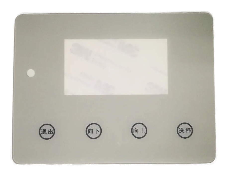
Use the keypad route when many discrete channels need a shared map and simultaneous-input rules.
Review Resource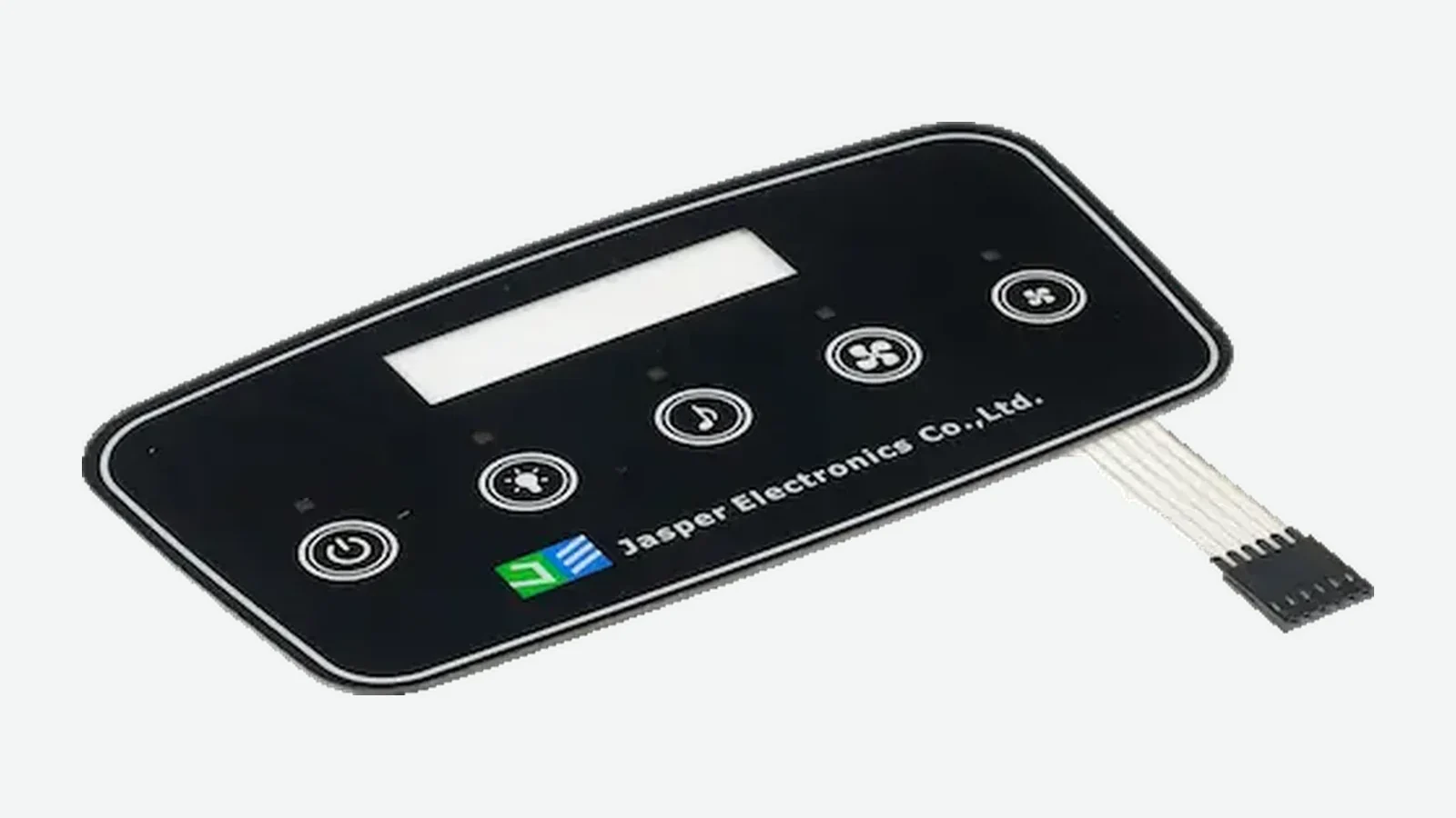
Compare no-travel capacitive commands with printed membrane-switch constructions.
Review ResourceJASPER can review the icon, electrode, cover, spacing, routing, nearby metal, controller boundary, feedback, false-touch states, and production evidence as one capacitive touch switch project.
Share the project basics. JASPER will review the stack, materials, connector, quantity, and production risks.