
In a capacitive touch vs membrane switch decision, choose capacitive sensing when the product needs an unbroken dielectric front, display-adjacent controls, or sliders and gesture-like input—and the project can own a controller, firmware, grounding, and installed-state validation. Choose a membrane switch when deliberate force, physical key confirmation, gloved operation, and straightforward discrete inputs matter more. Neither answer is automatic: the named glove, liquid, enclosure, feedback method, EMC requirement, and host electronics can reverse the choice.
1. Quick Verdict: Match the Interface to the Hardest Operating State
The best HMI input technology is the one that still produces the intended command—and rejects the unintended one—during the project's hardest credible state. A dry bare-finger demonstration on a bench does not settle the decision.
| Project condition | Capacitive touch usually fits better | Membrane switch usually fits better | What still needs proof |
|---|---|---|---|
| One-piece glass or plastic face with no key travel | ✓ | Cover stack, sensitivity, false-touch rejection | |
| Physical confirmation without looking at the panel | ✓ | Force, travel, tactile ratio, audible or host feedback | |
| Slider, wheel, proximity, or display-adjacent control | ✓ | Electrode map, controller channels, UI behavior | |
| Deliberate input through a named work glove | Conditional | ✓ | Actual glove, posture, force, missed/false input rate |
| Water film or cleaning liquid on the active surface | Conditional | Conditional | Liquid, amount, dwell, sealing path, response and recovery |
| Direct connection to simple digital inputs | ✓ | Contact resistance limit, debounce, matrix/ghosting logic | |
| Low-power product with wake-on-touch needs | Conditional | Conditional | Whole-system current by operating state |
| Equipment with demanding EMC or ESD requirements | Conditional | Conditional | Installed assembly against the applicable equipment standard |
“Conditional” matters. A capacitive panel has no moving contact at the touch target, but that does not make the finished equipment automatically water-tolerant, glove-compatible, immune to interference, or lower power. A membrane front can be sealed and physically tactile, but openings, tail exits, enclosure joints, contact design, host scanning, and wear still need a specification.
2. What Is Actually Being Compared?
A useful touch panel vs membrane keypad comparison starts with system boundaries. Both products may present printed icons on a thin front. Their signal paths are different.
Capacitive touch panel: a measured change, then a decision
Custom capacitive touch panels place one or more conductive electrodes behind a dielectric cover such as glass, acrylic, polycarbonate, or a printed film stack. A controller measures a capacitance-related change. Its configuration and firmware then decide whether that change represents a valid key, slider, wheel, proximity event, or coordinate input.
Finger / specified glove
electrical coupling through the dielectric
Cover lens + print + adhesive + any controlled gap
Electrode geometry + routes + tail / connector
Touch controller + thresholds + filtering + baseline logic
Host command + visual / audible / haptic feedback
Electrode layout, overlay construction, hardware signal margin, and controller tuning form one coupled design problem. The controller is not a black box that repairs any sensor or cover stack. Nearby metal, ground, display electronics, cables, power states, temperature, and moisture can alter what the controller sees.
A “capacitive touch panel” can mean discrete printed keys without a display, touch zones around a display window, or a projected-capacitive touchscreen laminated to a display. Those scopes are not interchangeable. The RFQ must state whether it covers only the printed front and sensor, a controller board, programmed firmware, the display, or a complete HMI assembly.
Membrane switch: force closes a contact
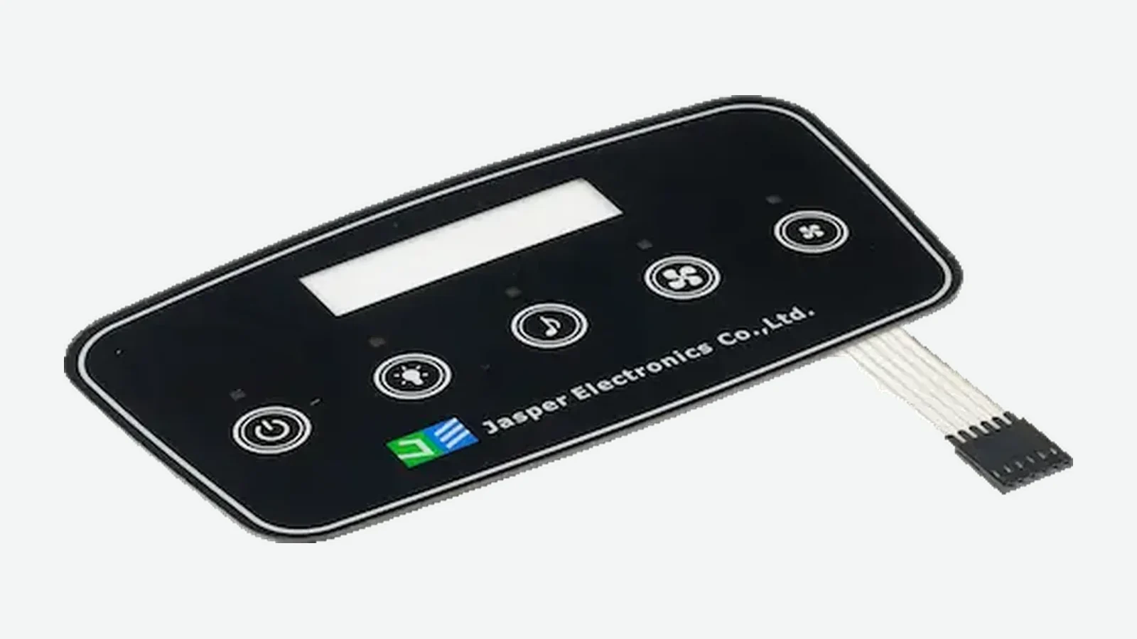
Custom membrane switches use a flexible contact construction. Pressing a key moves an upper conductive element or metal dome through a spacer opening to close a circuit on the lower layer. Releasing the key opens the momentary contact. A flexible tail carries rows, columns, commons, or individual circuits to the host.
Finger / tool / specified glove
mechanical force
Graphic overlay + optional embossing
Metal dome or flexible upper contact
physical contact closure
Printed circuit + tail + connector
Host input + debounce / matrix logic + feedback
A metal dome can add snap, travel, and sometimes sound. A non-tactile membrane contact may remain nearly flat and depend on visual or audible confirmation. “Membrane” therefore does not guarantee tactile feedback; the construction and acceptance values must say what the operator should feel.
The host electronics still matter. Matrix scanning can create different simultaneous-key rules than individual inputs. Debounce, pull-ups, LED branches, connector pinout, and fault detection remain electrical design tasks, even when the front assembly has no dedicated touch-sensing controller.

3. Capacitive Touch vs Membrane Switch: Engineering Matrix
This capacitive switch comparison separates inherent operating principles from project-dependent results. No row substitutes for testing the installed equipment.
| Dimension | Capacitive touch | Membrane switch | Decision boundary |
|---|---|---|---|
| Input principle | Controller measures a change associated with touch coupling | Mechanical force closes a normally open contact | Light/no-travel interaction versus deliberate force |
| Front construction | Continuous dielectric can cover all touch zones | Overlay flexes locally; embossed or flat keys are possible | Unbroken lens aesthetics versus key definition |
| Feedback | Requires visual, audible, or haptic feedback unless the surface itself moves | Metal dome can provide local snap; non-tactile versions still need feedback | Eyes-free or high-consequence commands favor explicit confirmation |
| Controller need | Dedicated sensing peripheral/controller, configuration, baseline logic, and often firmware | May connect to host GPIO or a key matrix; host still needs debounce and diagnostics as required | Electronics ownership and software change control |
| Gloves | Possible in some designed/tuned systems, not inherent | Force-operated keys are less dependent on electrical coupling | Name the glove, fingertip geometry, force, and posture |
| Moisture | Conductive films can change coupling or create apparent touches; water-tolerant modes require design and proof | Surface can shed liquid, but ingress paths and contact contamination remain assembly issues | Define response during exposure and recovery afterward |
| Display integration | Strong fit for touchscreens, sliders, and controls around a window | Windows, LEDs, and backlighting are possible, but dynamic coordinate input is not | Static command map versus changing screen UI |
| EMI / ESD | Small measured signals, sensor routes, ground, shields, and filters require attention | Contact closure is simpler, but long tails, ESD paths, LEDs, and host inputs still couple interference | Apply the finished-equipment EMC plan to either choice |
| Power | Depends on controller, scan rate, channels, wake mode, feedback, and host state | Contact layer may consume no steady sensing power; host scan, pull-ups, LEDs, and feedback still consume power | Compare system state budgets, not loose front panels |
| Validation | Cover, sensor, controller, firmware, ground, display, enclosure, environment, and host response | Force, contact, circuit map, tail, connector, sealing, host logic, and wear conditions | Capacitive usually has more coupled variables; membrane is not test-free |
| Change sensitivity | Cover, ink, adhesive, air gap, electrode, metal, display, or firmware changes may require retuning/retest | Dome, spacer, overlay, adhesive, circuit, substrate support, or host debounce changes may require retest | Freeze production-intent stack and revisions |
The matrix does not declare one universal winner. It reveals where each architecture stores risk. Capacitive touch stores more of the decision in analog measurement, controller behavior, and installed geometry. A membrane switch stores more in mechanical feel, contact construction, flexible routing, and repeated physical actuation.
4. Where Capacitive Touch Wins—and Where It Does Not
A continuous, cleanable front is part of the product architecture
A capacitive electrode can sit behind a continuous second-surface-printed cover. No key opening is required at the sensing location. That supports an uninterrupted glass or plastic face, dead-front graphics, and controls that share a visual language with a display. This is a construction advantage, not an ingress rating. IEC 60529 or a product-specific ingress requirement applies to the evaluated enclosure configuration, including edges, display bond, gasket, fasteners, tail exit, connector path, and housing joints; the IP65 vs IP67 membrane switch design guide explains that assembly boundary in more detail.
Capacitive touch is not the best choice merely because a surface must be wiped. A properly designed membrane-switch overlay can also present a closed, cleanable face. If a conductive liquid must remain on active keys while operation continues, both architectures need a state-based test rather than a “sealed” adjective.
Dynamic and display-adjacent controls justify the controller
Sliders, wheels, proximity wake, multi-key gestures, and projected-capacitive coordinate input can reduce mechanical key count and align controls with changing screen content. Controller channel count and sensing mode must cover every released button, slider, wheel, or proximity function without assuming that one device family fits every panel. A project that needs a display window, bonded sensor, and controlled interconnect can continue into the capacitive HMI front panels scope after choosing the architecture.
If the product only needs six fixed on/off commands, the additional sensing controller and firmware may not earn their place. A membrane switch can route six individual contacts or a small matrix directly to the host. The better answer follows the UI behavior, not the appearance trend.
No local contact closure removes one mechanism, not all failure modes
A capacitive key has no dome or flexing contact at the touch target. That removes contact bounce and local mechanical contact wear from the sensing method. It does not prove unlimited interface life. Cover abrasion, coating wear, adhesive changes, connector damage, controller drift, display noise, cracked lenses, and software revisions can still end the useful life of the assembly.
For heavy impact, a thick protective cover may be attractive, yet added dielectric distance reduces available touch signal and changes electrode requirements. Cover-lens thickness, gloves, water tolerance, temperature, mechanical design, and electrical design are linked choices. The recommended construction is not automatically capacitive when impact protection or a very thick cover dominates; the actual stack may favor a force-operated key, piezo input, mechanical control, or a guarded hybrid.
5. Where Membrane Switches Win—and Where They Do Not
Physical snap can confirm a command at the finger
A metal-dome membrane key can supply force, travel, snap, and sometimes audible feedback at the point of use. That can help an operator identify a deliberate actuation without watching a display. The drawing should define the chosen dome, supported area, overlay emboss, nominal force or force band, travel/feel expectation, and sample-approval method. These inputs sit alongside the overlay, spacer, adhesive, and printed conductor choices covered in the membrane switch materials guide.
ASTM F1570 historically defined a test method for membrane-switch tactile ratio, but ASTM marks F1570-01 as withdrawn. It should not be cited as current certification. A project can still measure actuation and return forces and calculate a tactile relationship under an agreed fixture; acceptance belongs in the controlled drawing and sample report.
Tactility is not always desirable. A quiet bedside control, wipe-flat laboratory surface, or high-density panel may use non-tactile contacts. If the UI needs changing labels, scrolling, or coordinate input, a fixed printed key map becomes the wrong tool.
Force-operated input reduces dependence on electrical coupling
A work glove changes the capacitance path between an operator and a capacitive electrode. A membrane key responds to sufficient mechanical force and travel, so glove dielectric properties are usually less central. Key size, spacing, emboss, actuation force, glove bulk, operator angle, and the ability to feel the snap still matter. A small flush key can remain difficult to find through a thick glove even if its circuit closes correctly.
This is why “glove compatible” is incomplete for either technology. The acceptance record should identify the glove manufacturer/type or controlled equivalent, dry/wet condition, operator posture, required force, adjacent-key behavior, missed inputs, false inputs, and recovery.
Discrete contacts can simplify the electrical boundary
A membrane tail can expose individual contacts, commons, or a matrix to the host. For fixed-function equipment, that boundary can be easier to diagnose than an analog sensing chain with tunable thresholds and baseline tracking. Production inspection can verify circuit mapping, continuity or resistance criteria, tail orientation, connector contact side, and key closure. The membrane switch circuit design guide carries that review into matrix routing, LED branches, shielding, tail layout, and pinout release.
The recommended construction is not automatically a membrane switch when the host needs a large dynamic command set, gesture input, or direct interaction with screen content. It is also not the default for every high-use control: service life depends on the specified dome/contact, support, force, environment, circuit materials, and test method. Universal “one million press” claims were excluded because no project evidence supports them here.
6. Gloves, Moisture, EMI, Power, and Validation
Treat glove and moisture behavior as operating states
The capacitive interface must handle noise, moisture, and changing temperature explicitly. Handling does not always mean accepting normal input. A safe specification may require the equipment to reject all touch while a water film is present, accept only a long press, switch to a wet profile, report a fault, or recover within a stated time after wiping.
| State to test | Applied condition | Valid input expectation | Invalid input expectation | Recovery evidence |
|---|---|---|---|---|
| Dry bare finger | Production cover, normal posture | Every intended key/zone; required multi-touch rule | No adjacent or edge activation | Baseline and host event log |
| Specified dry glove | Named glove and size | Required commands at defined locations | No extra command from broad fingertip contact | Repeat after removal/reapplication |
| Specified wet glove | Named glove plus controlled liquid | Project-defined: accept, restrict, or inhibit | No hazardous or adjacent command | Wipe/dry sequence and return time |
| Water droplets | Defined volume, locations, dwell | Project-defined behavior | Droplets must not create prohibited commands | Event log before/during/after |
| Continuous film or cleaning | Named liquid, amount, wipe tool | Often inhibit or restrict; project decides | No prohibited activation during wiping | Surface and function inspection |
| Condensation / temperature change | Defined profile in assembled equipment | Commands per state specification | No drift-driven event | Stabilization and retest record |
A physically sealed front and correct input behavior are separate questions. One concerns ingress paths through the assembly. The other concerns whether the input system recognizes or rejects events under a surface condition.
EMC and ESD belong to the finished equipment configuration
Capacitive sensing measures small changes, so electrode routes, reference ground, shielding, scan timing, filtering, nearby switch-mode power supplies, display refresh, LED currents, cables, and metalwork can affect signal margin. A membrane contact is a larger state change, yet its tail and host input can still collect radiated or conducted interference, and its exposed front can provide an ESD coupling path.
IEC 61000-4-2:2025 defines ESD immunity requirements and test methods for electrical and electronic equipment subjected to discharges from operators and to adjacent objects. It does not make a loose capacitive sensor or membrane switch “IEC 61000-4-2 certified.” The product or product-family standard, test levels, discharge points, mounting, cables, power mode, functional criteria, and recovery rules determine the actual plan. IEC describes its basic EMC publications as building blocks used by generic and product standards.
The installed prototype should include the production-intent display, bezel, ground, shield, cable set, power supply, enclosure, controller and firmware revision. A loose panel on a quiet bench cannot demonstrate final EMC behavior.
Compare power by state, not by product label
For capacitive touch, record active scan, idle scan, wake-on-touch, sleep, startup, fault, and feedback states. Channel count, scan rate, measurement method, filtering, controller, LEDs, display, haptic motor, and host wake policy all affect current. For a membrane switch, the contact layer may draw no steady sensing current while open, but host pull-ups, matrix scanning, illumination, debounce, diagnostics, and feedback still consume energy.
The useful RFQ input is a state budget: allowable current in sleep and active modes, wake latency, number of channels, required response time, and which controller remains powered. A generic claim that membrane is “passive” or capacitive is “low power” is not enough to size a battery.
Validation effort follows the number of coupled variables
Capacitive systems typically need more installed-state validation because a cover, print layer, adhesive, air gap, electrode, controller setting, ground, display, metal feature, or firmware change may shift the measured signal. Membrane systems reduce that analog tuning burden but add mechanical controls: dome placement, support flatness, spacer venting, actuation force, contact response, tail handling, and repeated-operation conditions.
Use the same five-step discipline for either architecture:
- Freeze the production-intent physical stack and controlled drawing.
- Record the electronics, firmware, configuration, and host revision.
- Install the sample in representative equipment.
- Run the agreed operator, liquid, power, noise, and recovery matrix.
- Link results, exceptions, and change authority to the released revisions.
JASPER's capacitive touch control panel case illustrates this installed-signal-chain boundary without naming a customer or claiming an unverified field result.
7. Decision Matrix: Which HMI Input Technology Should You Pick?
Choose from the hardest requirement outward. Do not start with the preferred surface appearance and retrofit the input logic later.
| If the dominant requirement is… | Starting architecture | Why | Reason to overturn it |
|---|---|---|---|
| Fixed commands with deliberate local confirmation | Tactile membrane switch | Force and snap can confirm actuation | Required force, noise, or key travel is unacceptable |
| Unbroken lens with display-adjacent keys or sliders | Capacitive touch | Electrodes can sit behind one dielectric face | Glove/liquid/noise margin cannot be validated |
| Thick work gloves and eyes-free operation | Membrane switch | Mechanical input depends less on electrical coupling | Key cannot be located or actuated safely through the glove |
| Dynamic screen navigation or coordinate input | Projected-capacitive touchscreen | Controls can follow screen content | Accessibility, critical-command, water, or service needs require separate hardware controls |
| Battery product with rare input | Compare both by measured state budget | Either can support low-energy designs | Controller/wake latency or illumination dominates power |
| Frequent cleaning but no operation during wiping | Either, with a sealed assembly | Both can present a cleanable front | Chemical compatibility or ingress path rejects one stack |
| Operation while wet | Neither by assumption | Input and rejection states need project proof | Choose only after installed wet-state evidence |
| Critical stop/reset or guarded command | Often a separate mechanical/guarded control | Independent, unmistakable action may be required | Final risk analysis and governing equipment standard decide |
| Main navigation plus a few critical fixed commands | Hybrid HMI | Capacitive display plus physical keys separates roles | Added parts, software, or enclosure complexity is not justified |
The “neither” outcome is real. Heavy impact, service replacement, intrinsically safe design, strict accessibility, emergency-stop architecture, or a governing product standard may point to a mechanical pushbutton, sealed keyboard, piezo control, rotary encoder, or another input method. This article cannot replace the finished equipment's hazard analysis or usability engineering.
8. Freeze These Inputs Before the RFQ
A supplier cannot compare technologies on artwork and annual quantity alone. Send one package that gives mechanical, electrical, firmware, environmental, and approval teams the same system boundary.
| Input group | Minimum information for a comparable review |
|---|---|
| Operator and commands | User roles, fixed/dynamic commands, eyes-free needs, simultaneous input, long press, prohibited events, feedback |
| Glove and liquid | Named glove; dry/wet state; liquid/cleaner; amount, location, dwell, wipe method; expected operation and recovery |
| Cover and graphics | Material/grade, thickness and tolerance, coating, print side, ink build, icon/window datums, adhesive, gaps, cosmetic zones |
| Sensor or contact map | Capacitive electrodes/routes/guards or membrane key/dome/contact/spacer map; edge and adjacent-key rules |
| Tail and connector | Exit, route, length, bend, contact side, stiffener, connector, pinout, test access, assembly sequence |
| Electronics boundary | Controller/host owner, candidate device, channels, interface, power states, firmware/configuration, diagnostics, change authority |
| Installed hardware | Display, LEDs, metal, ground, shield, enclosure section, gasket/bond, cables, power supply, likely noise sources |
| Standards and evidence | Applicable equipment standard, EMC/ESD/ingress/chemical tests, functional criteria, sample quantity, report format, approval sign-off |
Then approve in sequence:
1. Architecture review
choose capacitive, membrane, hybrid, or another input method
2. Drawing and responsibility release
freeze stack, map, tail, electronics boundary, and owners
3. Production-intent sample
inspect the physical panel and electrical mapping
4. Installed-state validation
run glove, liquid, power, noise, feedback, and recovery matrix
5. Revision release
sign drawings, configuration, evidence, exceptions, and change rules
Before requesting price, use the chosen technology to define the quotation scope. JASPER can review the physical panel, interconnect, and assembly boundary through its manufacturing capabilities and engineering review process. The quotation should state separately who owns the controller, firmware, display, final equipment tests, and compliance decision. quality and testing review requirements belong in the RFQ even if that site route is not yet live.
9. Frequently Asked Questions
Is capacitive touch better than a membrane switch?
Neither is universally better. Capacitive touch fits an unbroken dielectric front, dynamic controls, sliders, and display integration when the project can validate the sensor, controller, firmware, ground, enclosure, and operating states. A membrane switch fits deliberate physical input, tactile confirmation, named-glove use, and straightforward discrete commands when its mechanical and environmental conditions are verified.
What is the main difference in capacitive touch vs membrane switch operation?
Capacitive touch measures an electrical change associated with coupling through a cover, then a controller decides whether an event is valid. A membrane switch uses force to bring conductive elements into contact and close a circuit. That difference drives the controller, feedback, glove, moisture, power, and validation tradeoffs.
Will a capacitive touch panel work with gloves?
It can, but ‘works with gloves’ is not a complete specification. Performance depends on the named glove, fit, thickness, moisture, contact area, posture, cover stack, electrode, controller, configuration, ground, and noise environment. Test actual production-intent gloves in the installed equipment and define both accepted and rejected inputs.
Is a membrane keypad waterproof?
Not by itself. A membrane overlay can form part of a sealed front, but the evaluated assembly includes perimeter adhesive, windows, embossing, vent paths, tail exit, connector, gasket, fasteners, and enclosure joints. State the target ingress condition and test configuration rather than assigning an IP rating to an unevaluated loose keypad.
Which option uses less power?
There is no universal winner. A capacitive design’s current depends on controller, channel count, scan timing, filtering, wake mode, feedback, and host state. An open membrane contact may draw no steady sensing current, yet pull-ups, scanning, LEDs, diagnostics, and host logic consume power. Compare measured sleep, wake, active, fault, and feedback states.
Which interface handles EMI and ESD better?
Either can pass a properly designed finished-equipment test, and either can fail. Capacitive sensing is sensitive to sensor routing, ground, metal, display and power noise; membrane tails and host inputs also couple interference and ESD. Use the applicable equipment standard and test the production-intent enclosure, cables, power, electronics, and firmware—not a loose panel.
Can one HMI use both capacitive touch and membrane keys?
Yes. A hybrid can use capacitive touch for navigation, sliders, or display interaction and physical membrane keys for fixed commands that need local confirmation. It is worthwhile only when the human-factors split justifies extra parts, routing, controller channels, software states, assembly steps, and validation.
What should an OEM send before choosing a touch panel vs membrane keypad?
Send the command map, operator and feedback needs, named gloves and liquids, cover/enclosure drawings, display and metal locations, sensor or contact concept, tail/connector, controller boundary, power states, applicable equipment standards, and sample acceptance matrix. Choose the architecture before asking suppliers for a production quotation.
Technical References
- Source: Texas Instruments CapTIvate Technology Guide. Accessed 2026.
- Source: Microchip AN2934 Capacitive Touch Sensor Design Guide. Accessed 2026.
- Source: IEC 61000-4-2:2025 electrostatic discharge immunity. Accessed 2026.
- Source: IEC 60529 enclosure protection classification. Accessed 2026.
- Source: Texas Instruments, *CapTIvate Technology Guide 1.83.00.08 — Design Guide. Accessed 2026.
- Source: Texas Instruments, *CAPTIVATE-EMC. Accessed 2026.
- Source: Microchip Technology, *AN2934 Capacitive Touch Sensor Design Guide. Accessed 2026.
- Source: Microchip Technology, *AT09363 PTC Noise Tolerance Design Guide. Accessed 2026.
- Source: Infineon Technologies, *AN90071 CAPSENSE MBR3 Design Guide. Accessed 2026.
- Source: Infineon Technologies, *Industrial Capacitive Touchscreen Design Made Simpler. Accessed 2026.
- Source: International Electrotechnical Commission, *IEC 61000-4-2:2025. Accessed 2026.
- Source: International Electrotechnical Commission, *Basic EMC Publications. Accessed 2026.
- Source: International Electrotechnical Commission, *EMC Product Standards. Accessed 2026.
- Source: ASTM International, *ASTM F1570-01. Accessed 2026.
- Source: JN White, *Membrane Switch Design Guide. Accessed 2026.
Choose the input technology from the hard operating state
Send the cover stack, glove and liquid states, feedback method, controller ownership, EMC target, host interface, and installed validation plan.