Dongguan, Guangdong 523927, China[email protected]+86 136 3262 5290
Home / Products / Capacitive Touch Panels / Custom Capacitive HMI Front Panels
PHYSICAL OPERATOR-FRONT SUBASSEMBLIES

Custom Capacitive HMI Front Panels

A capacitive HMI front panel is a ready-to-integrate physical operator-front subassembly built from an explicitly released scope: cover, printing, sensor, PCB or FPC, connector, display window, lighting, adhesive or gasket, carrier, defined function test, packaging, and change control. A display module, processor, runtime, PLC, machine logic, regulatory approval, and complete-machine validation are excluded unless individually listed.

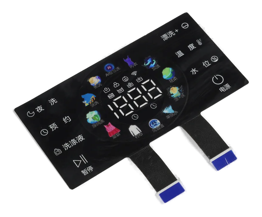
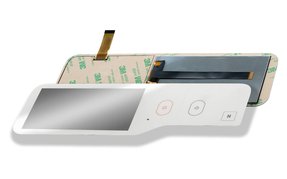
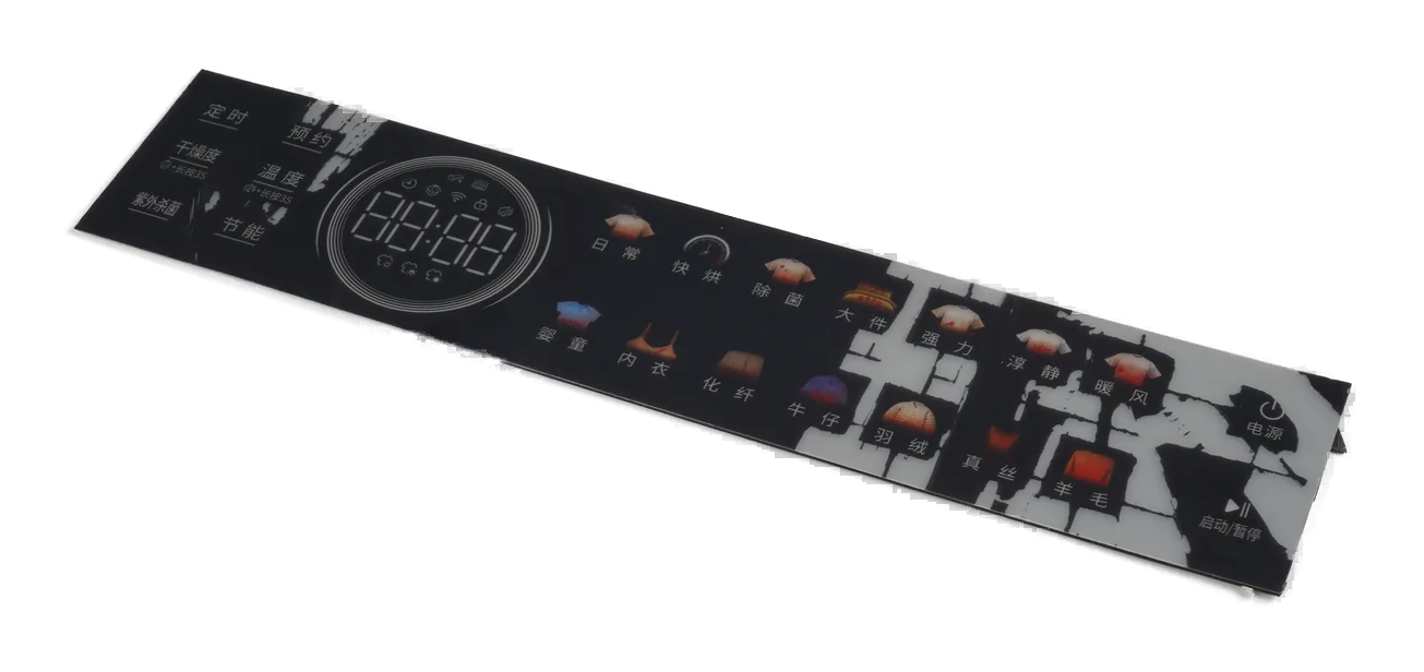
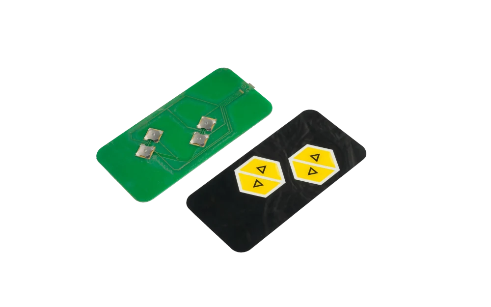
Layered capacitive operator front with cover, sensor, circuit, carrier, and connector
Front stack ownedcover, print, sensor, interconnect, window, lighting, bond, gasket, and carrier
Handoff definedconnector, mounting datums, mating surfaces, packaging, labels, and integration state
Evidence boundedvisual, dimensional, electrical, touch, lighting, assembly, and approved function checks

The Deliverable Stops at the Released Physical Operator Front

This route combines the capacitive sensing surface with selected physical front-panel layers and hardware so the customer receives a controlled subassembly rather than unrelated loose parts.

The exact bill of material may include a cover, graphics, sensor, PCB or FPC, connector, display window, lighting, adhesive, gasket, carrier, fasteners, labels, and packaging. Each included item must appear on the quotation and released assembly definition.

A front-panel subassembly is not automatically a complete HMI. Display modules, processors, runtime software, PLC content, machine behavior, regulatory approval, and whole-product validation remain outside scope unless explicitly added.

Custom Capacitive HMI Front Panels fit when:

  • the customer wants one physical operator-front subassembly ready for product integration
  • cover, sensor, circuit, connector, window, lighting, bond, gasket, and carrier boundaries can be released
  • the mating enclosure, host electronics, software, and machine responsibilities are identified
  • incoming, assembly, function, packaging, and change-control evidence can be agreed before production

Six Controls Keep a Front Subassembly from Becoming an Undefined HMI

The largest risk is often not one layer; it is an unspoken responsibility between the front-panel supplier and the system owner.

01

Scope and bill of material

Control

List every supplied cover, print, sensor, PCB or FPC, connector, window, light part, adhesive, gasket, carrier, fastener, label, and pack item.

Failure mode

A needed part or process exists in the concept image but not in the released supply scope.

02

Cover, print, and window

Control

Control outline, cosmetic zones, artwork, surface, clear aperture, black mask, touch icons, viewing state, and protected handling.

Failure mode

The front looks acceptable loose but conflicts with the display or enclosure after integration.

03

Sensor and electronics interface

Control

Release electrode map, controller boundary, PCB or FPC, pinout, connector, flex exit, grounding, host interface, and configuration ownership.

Failure mode

The physical connector mates while signals, tuning, or channel assignments remain incompatible.

04

Bond, gasket, and carrier

Control

Define adhesive coverage, gasket path, carrier material, datums, support, mounting, compression direction, and assembly sequence.

Failure mode

Stack position or local support changes touch behavior, window registration, or fit.

05

Function-test boundary

Control

Name visual, dimensional, continuity, touch, lighting, communication, fixture, host simulation, and excluded system tests.

Failure mode

A component check is mistaken for approval of the display, software, PLC, or machine operation.

06

Packaging and change control

Control

Release protective films, trays, separators, connector protection, labels, revision identity, traceability, substitutions, and requalification triggers.

Failure mode

Approved surfaces or configurations are damaged, mixed, or changed before customer integration.

Release the Front Assembly by Layer, Interface, and Evidence

A useful assembly specification says what JASPER supplies, what the customer supplies, where they meet, and what each test proves.

DecisionOptions to ReviewRelease Question
Front constructionGlass, polymer, printed cover, capacitive sensor, spacer, adhesive, gasket, carrier, fastener, and protective filmWhich physical layers arrive as one controlled front assembly?
Visual featuresTouch graphics, display window, black mask, dead-front details, illuminated icons, surface zones, and cosmetic boundariesWhich lit, unlit, powered, and unpowered appearances are included in approval?
Electrical interfaceSensor tail, PCB or FPC, controller included or excluded, connector, pinout, grounding, lighting circuit, and test accessWhat electrical state exists at the customer handoff connector?
Mechanical handoffMounting datum, carrier, studs, holes, adhesive liner, gasket, display relationship, enclosure support, and assembly directionHow does the customer locate and support the front without shifting the released stack?
Function evidenceDimensions, appearance, continuity, fixed touch, coordinate sensing, lighting states, communication, and customer fixtureWhich checks apply to the front assembly and which remain system-owner validation?
Production controlApproved sample, revision marking, incoming records, substitutions, packaging, storage, traceability, and change notificationWhat prevents an unapproved physical or configuration change at integration?
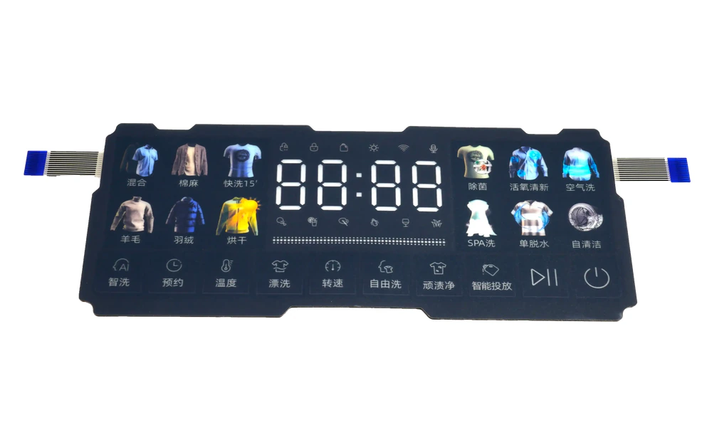
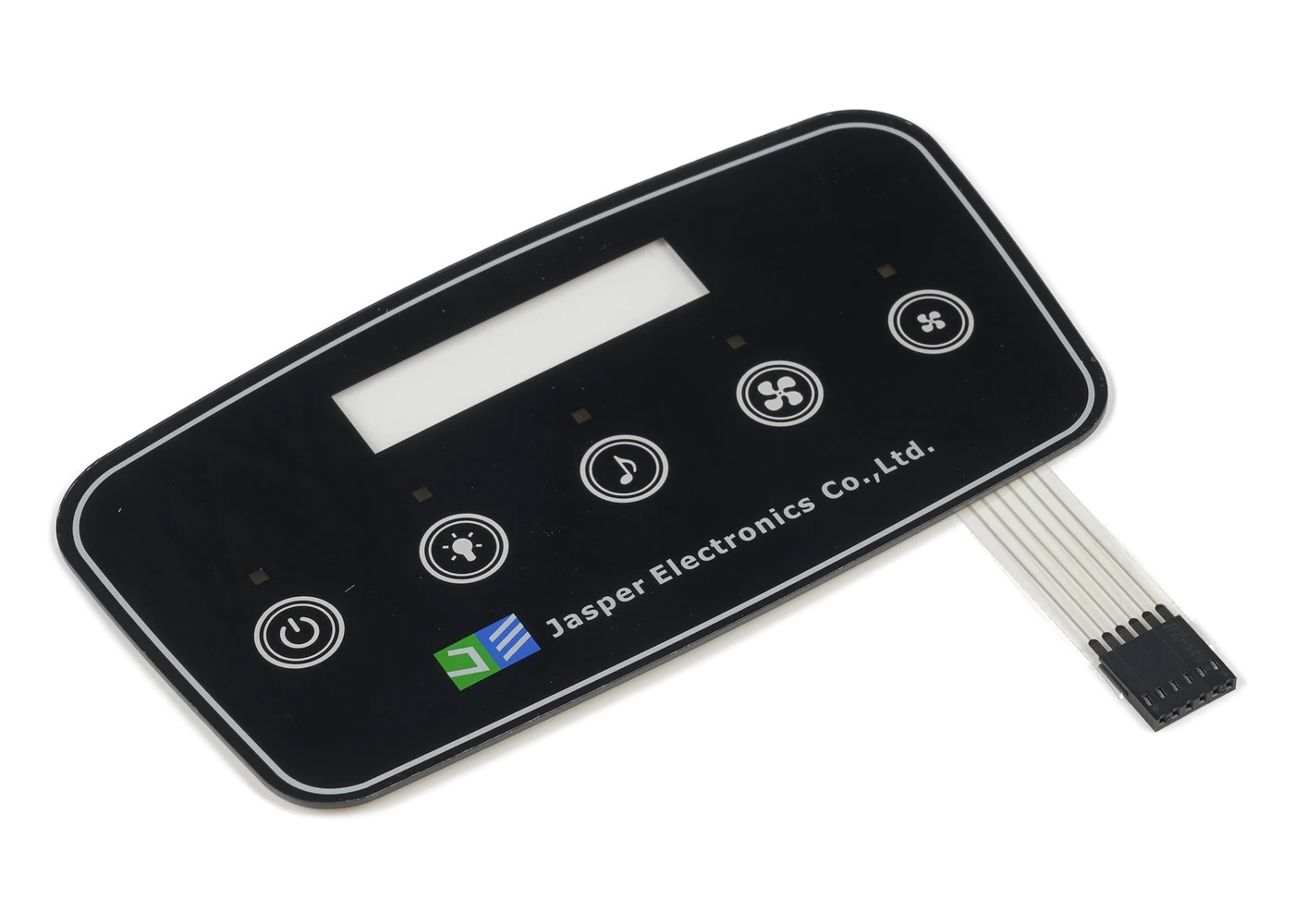
Finished capacitive HMI front subassembly prepared for enclosure integration
READY-TO-INTEGRATE PHYSICAL FRONT

Define the Customer Handoff State, Not Just the Exploded Stack

The useful deliverable is the approved physical condition received by the integrator: protective film status, connector orientation, adhesive liner, gasket, carrier, mounting datums, labels, packaging, and the evidence supplied with the part.

  • identify every installed and customer-installed item in the released bill of material
  • dimension mounting and display relationships from customer-usable datums
  • protect cosmetic surfaces, flexes, connectors, liners, and gaskets through shipment
  • define the exact test state and records delivered with the front assembly
Capacitive front-panel layers ending at a defined host-system connector boundary
RESPONSIBILITY BOUNDARY

Keep Front-Panel Function Separate from Complete HMI and Machine Approval

Touch response, lighting, continuity, connector output, or communication can be checked at the front-panel boundary. Those checks do not by themselves validate a display module, processor, runtime, PLC program, machine logic, safety function, or finished equipment.

  • name the controller and firmware owner when either affects acceptance
  • list any display module or host electronics only when they are actually supplied
  • separate front-panel fixtures from customer system and machine validation
  • route broader electronics and software ownership to the HMI assembly scope

Build the Front Assembly Around a Written Responsibility Matrix

01

Set the supply boundary

Mark every included and excluded cover, sensor, circuit, connector, window, light, bond, gasket, carrier, display, and electronic item.

02

Align interfaces

Review artwork, touch map, display relationship, enclosure datums, mounting, connector, pinout, grounding, flex, and assembly direction.

03

Plan the build sequence

Define printing, lamination, bonding, gasket placement, circuit attachment, carrier assembly, cleaning, protection, and handling.

04

Approve the handoff

Inspect appearance, dimensions, touch, lighting, electrical interface, fit fixture, labels, packaging, and agreed function checks.

05

Control repeat builds

Lock bill of material, approved sources, revisions, fixtures, records, packaging, substitutions, notification, and requalification triggers.

Use the Handoff Boundary to Diagnose Front-Panel Failures

01

Front does not fit

Check mounting datums, carrier, gasket, adhesive, fasteners, enclosure support, display position, stack sequence, and drawing revision.

02

Connector or signal mismatch

Compare connector keying, pinout, cable orientation, controller boundary, grounding, host interface, configuration, and test fixture.

03

Visual or lighting mismatch

Review artwork, window registration, mask, surface handling, LED assignment, optical stack, display relationship, and approval state.

04

Function differs after integration

Separate front-panel evidence from host power, firmware, processor, runtime, PLC, enclosure, display, and machine conditions.

Where Capacitive HMI Front Panels Fit

01

Industrial equipment fronts

Physical operator fronts supplied with defined sensing, interconnect, mounting, and customer handoff checks.

02

Laboratory instrument panels

Controlled cover, window, touch, lighting, carrier, and connector assemblies for customer electronics.

03

Appliance control fronts

Ready-to-install physical interfaces with released artwork, sensor, circuit, adhesive or gasket, and carrier.

04

Building-control panels

Custom room, access, and equipment fronts delivered to a defined host connector and enclosure datum.

05

Transportation operator panels

Physical front subassemblies coordinated with customer display, host electronics, mounting, and validation.

06

Specialty machine interfaces

Custom fronts for system integrators that retain processor, runtime, PLC, and whole-machine responsibility.

Send the Front-Assembly Bill of Material and Responsibility Matrix

The quotation can only be precise when supplied parts, customer parts, handoff interfaces, tests, and exclusions are visible in the same package.

  • front outline, cover, print, touch zones, display window, lighting states, and cosmetic zones
  • sensor, PCB or FPC, controller boundary, connector, pinout, grounding, flex, and test access
  • adhesive, gasket, carrier, fastener, enclosure, mounting datum, display relationship, and build sequence
  • included and excluded display module, processor, runtime, PLC, host electronics, and machine functions
  • visual, dimensional, electrical, touch, lighting, communication, fixture, and system-test boundaries
  • prototype quantity, annual estimate, labels, packaging, records, traceability, and change control
Send Front Assembly Files

Custom Capacitive HMI Front Panels FAQ

What is a capacitive HMI front panel?

It is a released physical operator-front subassembly that may combine the cover, graphics, sensor, circuit, connector, window, lighting, bonding, gasket, carrier, and defined front-panel tests.

Is the display module included?

Only when it is explicitly listed in the quotation, bill of material, assembly drawing, and test scope. A display window or display relationship does not imply that JASPER supplies the display.

Are the processor, runtime, PLC, and machine logic included?

No, unless each item is deliberately added to a broader scope. This page stops at the physical operator-front subassembly and its defined interfaces.

What function testing can be included?

The project may define visual, dimensional, continuity, touch, lighting, communication, or fixture checks at the front-panel boundary. Those checks do not replace finished-system validation.

When should a project move to an HMI assembly route?

Use the HMI assembly route when responsibility must extend through supplied displays, processor electronics, broader wiring, software or runtime integration, enclosure modules, or higher-level functional validation.

Related Capacitive Touch Resources

HMI Assemblies

HMI Assemblies

Review the broader route when physical, electronic, display, or system responsibility must extend beyond the front panel.

Review Resource

Release the physical front, handoff connector, and test boundary together.

JASPER can review the cover, print, sensor, PCB or FPC, connector, display window, lighting, bond, gasket, carrier, function evidence, packaging, and change controls as one front-panel subassembly.

Start Front Panel ReviewContact Engineering