
Window boundaries
ControlRelease display active area, display view area, clear aperture, black mask overlap, corner form, and enclosure opening.
Failure modeThe mask clips content or exposes an unapproved edge around the display.
A display-window capacitive panel combines a transparent viewing region, controlled black mask, and fixed capacitive keys, sliders, or icons around the display. The sensor, display, bonding layers, and enclosure must share one coordinate system so visible content and touch artwork remain registered.
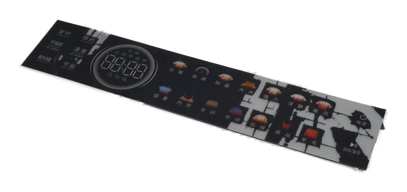
This construction preserves a transparent viewing area for a display while placing fixed capacitive control regions in the printed area around or beside it.
Display active area, view area, clear aperture, black mask, sensor electrodes, graphics, bonding layers, and enclosure opening are related boundaries. Each needs a released datum and acceptance state.
Optical bonding is not assumed. Air gap, perimeter attachment, selected adhesive interfaces, or a separately specified optical-bonding process must be named in the project scope.
A clean window sample is incomplete evidence when the mask, sensor, display, and enclosure were inspected separately.
Release display active area, display view area, clear aperture, black mask overlap, corner form, and enclosure opening.
Failure modeThe mask clips content or exposes an unapproved edge around the display.
Define color target, opacity direction, border construction, legend registration, pinholes, edge quality, and powered inspection.
Failure modeBacklight reveals print variation that was invisible on an unpowered sample.
Map keys, sliders, rings, guards, spacing, icons, channels, and inactive regions around the viewing area.
Failure modeA visible icon and its sensing electrode do not overlap after stack tolerances.
Locate cover, print, sensor, display, bonding layer, carrier, and enclosure from a named datum scheme.
Failure modeEach supplier centers its part independently and the final stack accumulates offset.
Identify air gaps, perimeter bonds, local adhesive, full-area processes, service needs, and who owns the display attachment.
Failure modeA bonding method is assumed late and changes appearance, stack position, or serviceability.
Review display model and modes, power conversion, grounding, controller placement, flex route, nearby conductors, and diagnostics.
Failure modeFixed keys become unstable only when particular screen content or power states are active.
The released drawing should make active area, view area, aperture, mask, touch zones, and enclosure registration unambiguous.
| Decision | Options to Review | Release Question |
|---|---|---|
| Display geometry | Active display area, supplier view area, outline, frame, polarizer edge, mounting, and cable exit | Which display boundary must remain visible and which may sit behind the mask? |
| Clear aperture | Transparent opening, corner form, decorative border, surface treatment, inspection background, and protected zones | What is the approved clear region in powered and unpowered states? |
| Black mask and graphics | Printed mask, decorative color, legends, logos, dead-front details, registration marks, and opacity direction | How is mask overlap controlled without clipping the intended image? |
| Touch layout | Fixed keys, sliders, rings, proximity exclusions, guards, electrode map, channels, and feedback cues | Where must each sensing region sit relative to the visible icon and display edge? |
| Stack registration | Sensor, cover, display, adhesive, spacer, carrier, gasket, enclosure, and assembly sequence | Which datums and fixtures preserve the released relationship through assembly? |
| Electrical evidence | Controller state, display modes, grounding, noise checks, fixed-zone response, diagnostics, and retained sample | Which powered conditions prove the finished front panel is acceptable? |
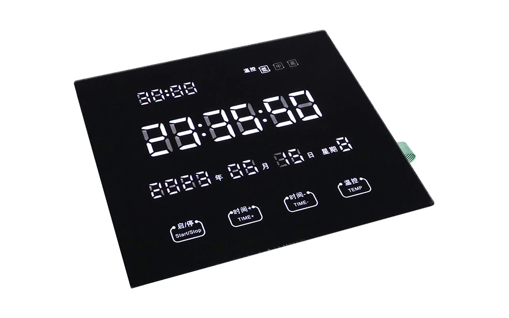
An unpowered inspection cannot reveal clipped pixels, exposed frame edges, mask show-through, adhesive boundaries, trapped contamination, or reflections created by the installed spacing. The display and front panel need a shared visual approval setup.
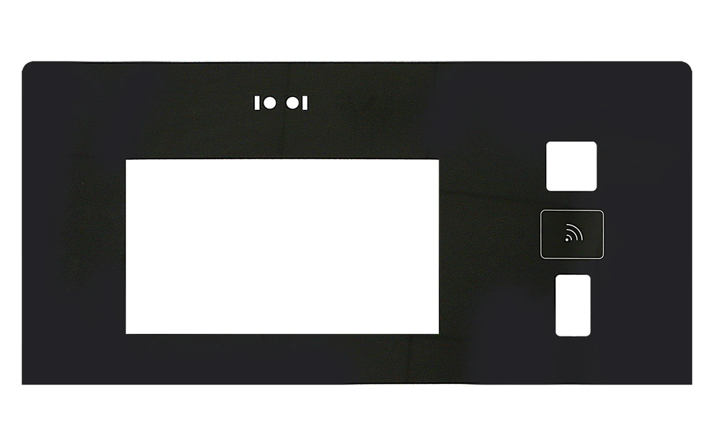
The visible icon, sensor electrode, controller channel, display edge, and enclosure support must remain in the intended relationship after printing, lamination, die cutting, bonding, and final assembly.
Record display model, active and view areas, screen orientation, required clear region, and hidden boundaries.
Place keys, sliders, rings, legends, exclusions, feedback, and controller channels around the window.
Align cover, mask, sensor, display, bonding, carrier, gasket, enclosure, flex, and connector from common datums.
Inspect window appearance, mask overlap, touch-zone response, display noise, fit, and cable routing together.
Control materials, print, sensor map, display reference, bonding scope, fixture, inspection, and change triggers.
Check active area, view area, mask overlap, aperture tolerance, display mount, enclosure opening, and assembly datum.
Compare artwork, electrode map, print registration, lamination, die cut, controller channel, and final panel position.
Inspect mask opacity, adhesive boundary, contamination, surface condition, spacing, display frame, and screen-content dependence.
Review display mode, grounding, power conversion, controller tuning, flex route, conductive carrier, and installed cable position.
A visible status or menu display paired with fixed capacitive commands around the window.
Front surfaces combining a readable display, fixed controls, cleaning considerations, and controlled registration.
Display windows with dedicated power, mode, navigation, or slider zones in surrounding artwork.
Thermostat, access, room, and equipment panels with a clear display region and fixed inputs.
Custom front panels where display boundaries, touch zones, lighting, and enclosure datums are coordinated.
Purpose-built interfaces that need a display aperture without adopting full coordinate sensing across the screen.
The most useful starting package shows what must be seen, what must be touched, and how the complete front stack is located.
It is a custom front panel with a transparent viewing area for a display and fixed capacitive controls arranged in the surrounding printed surface.
Not by default. This route centers on a viewing window plus fixed touch zones. Use the PCAP route when coordinates or multi-touch sensing are required across the display area.
No assumption is made. The project must state whether the display is separate, perimeter attached, locally bonded, full-area bonded by a named process, or supplied outside JASPER's scope.
They describe different boundaries. Separating them prevents the black mask or enclosure from clipping intended content or exposing an unwanted display edge.
Approve powered and unpowered window appearance, mask overlap, fixed-zone registration and response, display noise states, bonding boundary, fit, and cable routing.
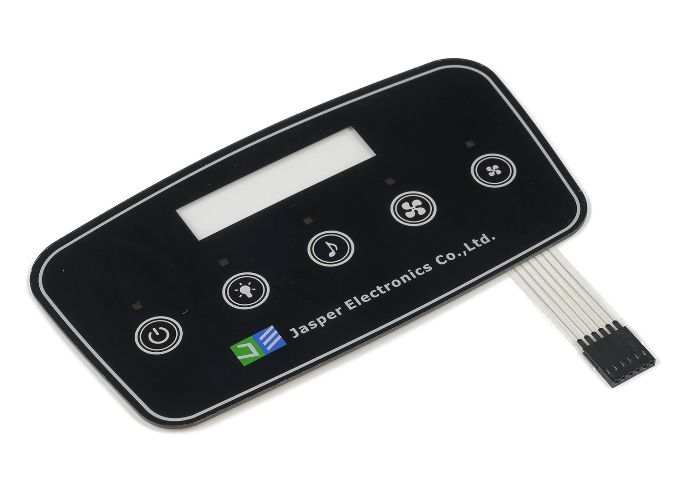
Compare fixed-control, display-window, PCAP, backlit, and front-panel constructions.
Review Resource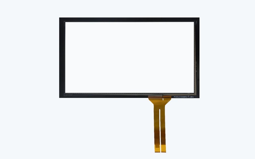
Choose coordinate and multi-touch sensing when interaction must extend across the display area.
Review Resource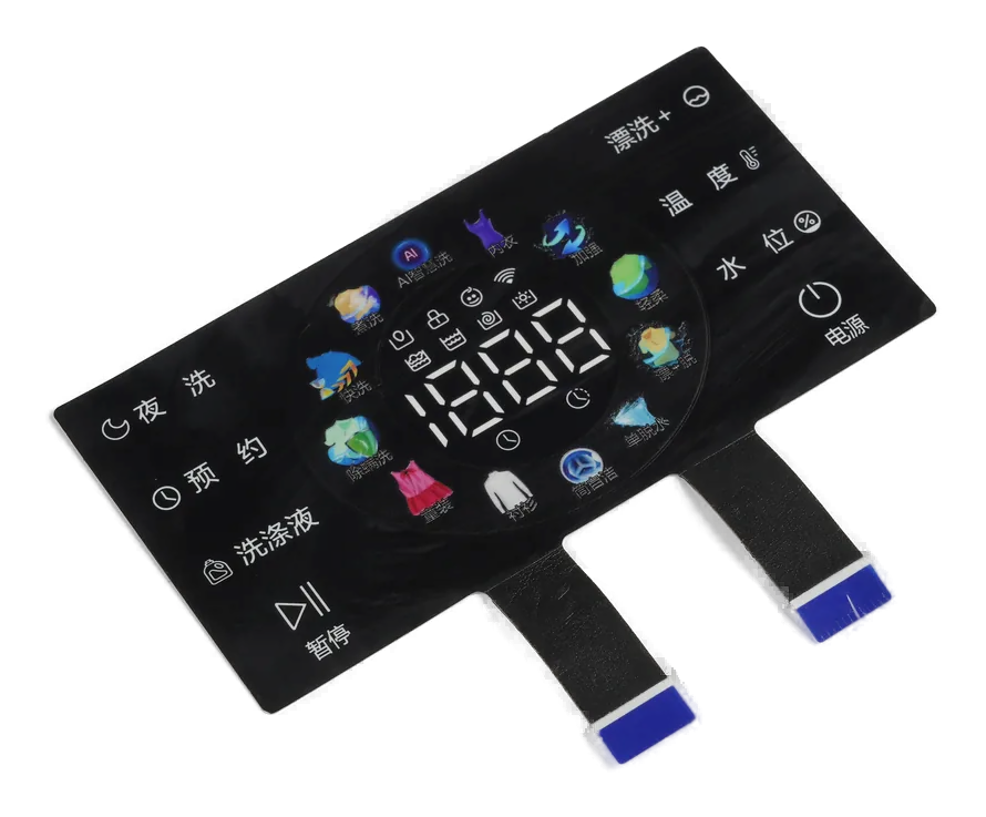
Add carrier, interconnect, lighting, gasket, and defined physical front-assembly responsibility.
Review ResourceJASPER can review the clear aperture, fixed controls, sensor, display boundary, bonding scope, enclosure datums, noise states, and powered inspection plan together.
Share the project basics. JASPER will review the stack, materials, connector, quantity, and production risks.