
Medical equipment does not share one default keypad
A diagnostic analyzer, bedside monitor, rehabilitation controller, and home-use device may all use membrane switches, but their users, cleaning routines, information density, and failure consequences are different. The interface review starts with the actual task, not the word medical.
Diagnostic and IVD analyzers
Benchtop analyzers, sample processors, point-of-care readers, and cartridge-based diagnostic instruments.
- Operating reality
- Operators move between sample handling, menus, status lights, and result review. Gloves, reagent residue, repeated wiping, narrow display windows, and several instrument states can meet on one front panel.
- Design direction
- Separate routine navigation from start, stop, eject, alarm, and service actions. Coordinate window clarity, indicator legends, key spacing, bezel openings, and the cleaning boundary with the instrument enclosure.
- Approval check
- Run representative workflows on an installed sample, then inspect key response, legends, window appearance, indicators, edges, and internal evidence after the specified cleaning sequence.
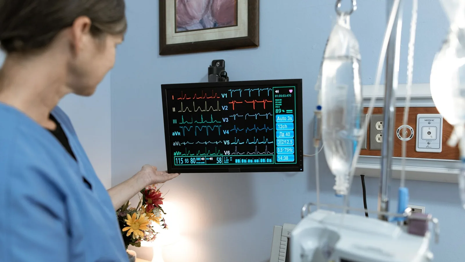
Patient monitoring and bedside equipment
Vital-sign monitors, bedside controls, nurse-call interfaces, transport monitors, and patient-care accessories.
- Operating reality
- Professional users may work quickly in low light, around alarms, cables, fluids, gloves, and frequent disinfection. Patients or caregivers may also operate a limited set of functions.
- Design direction
- Create an unmistakable hierarchy between patient-accessible, routine clinical, and protected service controls. Review night visibility, tactile location, alarm acknowledgement, cleaning access, and cable strain around the mounting area.
- Approval check
- Confirm control identification and feedback with intended users and lighting states. Clean the installed article using the labeled method, then repeat visual and functional checks without treating the panel as proof of the complete device alarm system.
Therapy and rehabilitation systems
Electrotherapy units, rehabilitation equipment, powered support devices, treatment tables, and operator pendants.
- Operating reality
- The operator may adjust settings while watching a patient, holding an applicator, or wearing gloves. Cables move, surfaces are wiped, and emergency or stop functions must remain distinct from incremental controls.
- Design direction
- Use key size, spacing, shape, color, and tactile response to separate high-consequence actions. Control tail routing, connector retention, pendant flex, housing edges, and the location of graphics that receive repeated thumb contact.
- Approval check
- Use a production-intent pendant or enclosure and complete representative adjustment, stop, cleaning, drop-handling, and cable-motion checks defined by the OEM test plan.
Medical laboratory equipment
Centrifuges, incubators, mixers, laboratory controllers, preparation equipment, and compact automation modules.
- Operating reality
- Small legends, timer or speed settings, glove use, reagent contact, status windows, and routine bench cleaning compete for limited panel area. Service access can disturb the same connector or tail used by the operator interface.
- Design direction
- Define readable text size and contrast, display-window tolerances, key grouping, chemical exposure zones, service clearances, and connector orientation before releasing the artwork.
- Approval check
- Inspect off-state and powered appearance, operate controls with intended gloves, repeat the named wipe procedure, and verify that servicing the enclosure does not bend or pull the tail outside its released route.
Portable and home-use devices
Handheld readers, compact therapy controllers, home monitoring equipment, and portable diagnostic accessories.
- Operating reality
- Lay users may have different strength, vision, dexterity, training, and access to cleaning supplies. The device can be held at changing angles, packed away, dropped, or operated in varied household lighting.
- Design direction
- Reduce control ambiguity, keep feedback visible from expected angles, select actuation force around the user group, protect the tail and connector inside the housing, and define a practical cleaning method for the intended setting.
- Approval check
- Evaluate representative users, tasks, lighting, grip, feedback, storage, and cleaning on the assembled device. The interface sample supports that work but does not replace the OEM human-factors validation.
Clinical support and bed controls
Hospital-bed handsets, chair controls, equipment carts, room accessories, and patient-positioning interfaces.
- Operating reality
- Controls may be used by staff and patients, exposed to repeated wipe-down, handled with limited dexterity, and pulled through cables or mounting clips. Icons must remain understandable without making unsafe functions easy to trigger.
- Design direction
- Assign control access by user, protect high-consequence functions, review emboss and tactile location, use durable sub-surface legends, and design the cable, strain relief, clip, and enclosure as one assembly.
- Approval check
- Check reach, force, icon comprehension, night use, cable motion, retention, cleaning, and post-cleaning function on the complete handset or mounted control supplied by the OEM.
Define the cleaning process before selecting the front stack
A smooth overlay can remove exposed key gaps, but cleanability is a finished-device property. Material compatibility, edge design, windows, seams, mounting pressure, labeling, and the actual wipe or disinfection method have to be reviewed together.
- 01
Name the procedure
List each cleaner or disinfectant, concentration, application method, contact time, temperature, rinse or dry step, and frequency.
- 02
Map exposed zones
Mark the face, edges, windows, key emboss, cable exit, bezel, screws, vents, labels, and housing joints reached by liquid or wiping pressure.
- 03
Release the construction
Freeze film, hard coat, ink, adhesive, circuit, dome or spacer, window, gasket, tail, connector, and mounting surface against the defined procedure.
- 04
Test the installed article
Apply the procedure to the production-intent assembly and record appearance, adhesion, readability, key function, optics, internal evidence, and recovery.
Chemistry and concentration
Trade names alone are not enough when formulations vary. Record the actual product or active chemistry, dilution, temperature, and any mixed-cleaner restriction supplied by the OEM.
Wet method and contact time
A damp wipe, saturated wipe, spray, pooling edge, foam, and immersion are different loads. State where liquid is applied and how long it remains.
Pressure and wiping media
Wipe material, hand pressure, scrub motion, number of passes, and contact with embossed edges can change ink wear, gloss, haze, and edge lifting.
Frequency and accumulated exposure
Define cleaning per shift, per patient, per use, or per service interval, plus the sample sequence that represents the project acceptance target.
Acceptance and device labeling
Name allowed color shift, gloss change, haze, adhesive movement, tactile change, electrical result, internal moisture evidence, and the owner of the finished-device cleaning instruction.
Do not infer sterilization, antimicrobial performance, biocompatibility, or universal disinfectant resistance from a flat overlay. Those claims require the applicable finished-device strategy, materials, procedure, and evidence.
Choose key feedback from the clinical task
Key feel should communicate the intended action without creating a cleaning trap or an accidental input. Criticality, user strength, gloves, press frequency, audio or visual feedback, and enclosure support determine the construction.
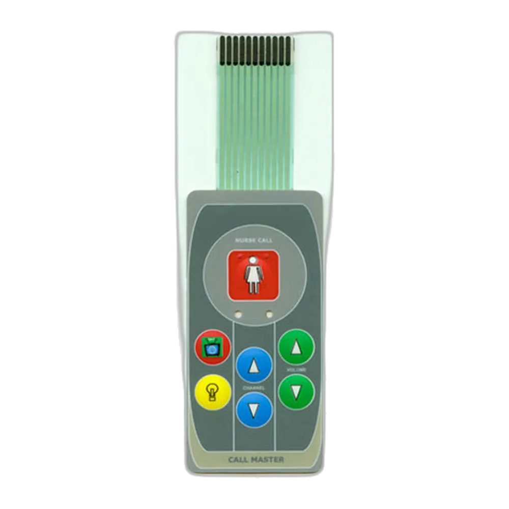
Low-profile non-tactile keys
Fits wipe-clean panels where software, sound, or visible state provides clear feedback and the user should not feel a metal-dome snap.
- Coordinate
- Coordinate spacer travel, force, active area, debounce, enclosure support, and cleaning pressure so wiping does not create unintended operation.
- Approve
- Approve with representative presses and cleaning loads on the installed panel, including low-force users where relevant.
Tactile metal-dome keys
Fits controls that benefit from a distinct snap and finger location, including frequent navigation or gloved professional use.
- Coordinate
- Coordinate dome force, diameter, emboss, key spacing, circuit contact, overlay stress, support plane, and expected audio or visual confirmation.
- Approve
- Compare approved force samples, operate with intended gloves, and record force or tactile acceptance at defined keys rather than accepting a generic feel.
Silicone keypad or hybrid front
Fits pronounced key travel, strong finger location, color-separated keys, or a molded front integrated with a rigid housing.
- Coordinate
- Coordinate silicone web, carbon contact or PCB interface, bezel clearance, compression, cleaning seams, legend method, and gasket ownership.
- Approve
- Approve the molded keypad in its actual bezel and PCB stack, then repeat operation and cleaning checks at edge and corner keys.
Capacitive or integrated HMI
Fits smooth fronts, larger displays, changing workflows, or assemblies where display, touch, bezel, PCB, and front glass should be reviewed as one module.
- Coordinate
- Coordinate glove and wet-touch behavior, false-touch controls, optical bonding, grounding, firmware, display states, service access, and cleaning lockout.
- Approve
- Validate the finished interaction with intended users and software states; a supplied touch component alone cannot establish medical usability or electrical safety.
Send the current package with open usability, material, window, and integration decisions marked.
Release every visible state, not only the print file
Medical interfaces are read in bright rooms, low light, from oblique angles, and during competing tasks. The approval set should show what the operator sees when the device is off, active, alarming, being cleaned, and viewed through the finished window stack.
Legends and control hierarchy
Define type size, contrast, icon meaning, language variants, color ownership, critical-action separation, and the relationship between printed labels and software text.
Approval evidenceApprove printed samples under named lighting and viewing distances, then retain the released artwork and color reference.
Display windows
Coordinate clear film, hard coat, adhesive, air gap, bezel overlap, anti-glare needs, active display area, contamination risk, and allowable haze or distortion.
Approval evidenceInspect the installed powered display at expected angles and brightness states before and after the project cleaning sequence.
Dead-front and backlit graphics
Specify the off-state concealment, on-state color and brightness, light source, diffuser, masking, leakage limits, and ambient-light range.
Approval evidenceApprove matched off/on samples rather than a standalone print, and include dim-room and bright-room appearance where the use environment requires both.
Indicators and alarm-related controls
Define which status comes from printed legend, LED, display, sound, tactile feel, or software and prevent one component from carrying ambiguous meaning.
Approval evidenceVerify indicator windows and key response in the finished device states. Alarm behavior and risk controls remain part of the OEM system validation.
The approval sample must represent the device interface
A loose switch can prove artwork and continuity, but not enclosure support, cleaning access, display alignment, cable routing, user reach, or software feedback. The release article should match the installation that will be manufactured.
- 01
Freeze intended use inputs
Record users, tasks, use environments, critical controls, cleaning method, lighting, gloves, feedback, enclosure, and applicable OEM risk controls.
- 02
Build the production-intent stack
Use released materials, windows, keys, circuit, tail, connector, adhesive or gasket, housing surface, display, and assembly method.
- 03
Run combined-use checks
Operate representative workflows and software states, inspect optics and feedback, apply cleaning or environmental sequences, and repeat functional checks.
- 04
Release evidence and revision
Record the approved sample, drawings, artwork, materials, dimensions, key map, inspection criteria, deviations, and ownership of finished-device validation.

What JASPER can control in component production
JASPER manufactures the released interface component or assembly and records the checks named on the project drawing and control plan. The useful handoff separates component evidence from medical-device claims that depend on the OEM system.
- Revision set
- Released artwork, circuit master, bill of materials, dimensions, key map, connector, and approved sample.
- Process route
- Printing, circuit production, precision cutting, lamination, assembly, and project-defined handling steps.
- In-process checks
- Registration, print appearance, dimensions, circuit continuity, dome or key placement, connector, and assembly condition where specified.
- Release records
- Visual, dimensional, functional, packing, labeling, and other project-defined inspection evidence tied to the released revision.
The OEM or medical-device CDMO remains responsible for intended use, risk management, human factors, biocompatibility where applicable, cleaning or sterilization labeling, software, electrical safety, regulatory submissions, and validation of the finished device.
Select the interface architecture
Use the product pages below to compare component construction. The medical application and finished-device requirements still control the final choice.
Custom membrane switch
A printed, low-profile control with project-specific keys, windows, tail, connector, adhesive, and inspection criteria.
Review product >Non-tactile membrane switch
A smooth key field for interfaces that rely on visual, audible, or software feedback and need controlled wipe behavior.
Review product >Backlit membrane switch
Integrated indicators, dead-front legends, or illuminated controls reviewed in both powered and unpowered states.
Review product >Complete HMI assembly
Display, touch or keypad, bezel, carrier, PCB, cable, and front interface coordinated as one released module.
Review product >Continue the engineering review
Close material, backlighting, drawing, and quotation inputs without repeating the entire product catalog on this application page.
Membrane Switch Design Guide
Review the layer stack, circuit, key feel, windows, tail, connector, and enclosure inputs.
Open resource >Membrane Switch Materials
Compare overlay films, hard coats, inks, circuits, adhesives, windows, and support layers by exposure.
Open resource >Backlighting Options
Define LED, light-guide, dead-front, masking, brightness, leakage, and powered-state approval needs.
Open resource >Membrane Switch RFQ Checklist
Organize the drawing, environment, quantities, connector, sample, and documentation package for review.
Open resource >Send the medical interface package before tooling
Early drawings are enough to start when they identify the intended user, cleaning process, interface boundary, and decisions that remain open. A useful quotation separates component requirements from finished-device validation work.
Open Medical Interface Project Form- device type, intended users, professional or home-use setting, and representative tasks
- front-panel, display, enclosure, mounting, bezel, and cable-route drawings
- critical and routine controls, key feel, force targets, gloves, feedback, and software states
- cleaner or disinfectant, concentration, method, contact time, frequency, rinse or dry step, and exposed zones
- legends, language variants, color references, windows, LEDs, dead-front graphics, and viewing conditions
- tail exit, bend route, connector, strain relief, shielding, grounding, and service access
- prototype quantity, annual estimate, sample deadline, approved-sample plan, and change-control expectations
- component inspection records, labeling, packing, regulatory-support documents, and OEM-owned validations required by the project
Medical Device Membrane Switch FAQ
Why are membrane switches used on medical equipment?
A membrane switch can combine printed legends, low-profile keys, display or LED windows, a flexible circuit, and a wipe-friendly front in one custom component. Suitability still depends on the intended user, task, cleaning method, enclosure, feedback, and finished-device validation.
How should cleaning chemicals be specified for a medical membrane switch?
Provide the cleaner or disinfectant, concentration, application method, contact time, temperature, rinse or dry step, frequency, wiping media, pressure or passes, exposed surface zones, and acceptance criteria. A generic statement such as hospital cleaner is not enough for material selection or sample testing.
Should a medical keypad use tactile or non-tactile keys?
Use the actual task to decide. Tactile metal domes can give a distinct snap and finger location, while non-tactile keys can support a smoother front when visual, audible, or software feedback is clear. Gloves, user strength, cleaning pressure, criticality, key spacing, and enclosure support should be reviewed on samples.
Can display windows and backlit indicators be integrated into the interface?
Yes. The overlay can include clear or filtered windows, dead-front graphics, LED indicators, and backlit legends. The project should define film, hard coat, adhesive, masking, brightness, light leakage, viewing angle, display alignment, and acceptance in powered and unpowered states.
Does JASPER provide finished medical-device approval?
No. JASPER can manufacture the released interface component and provide the project-defined component inspection evidence. The OEM or CDMO owns intended use, risk management, human factors, cleaning or sterilization labeling, software, electrical safety, regulatory submissions, and validation of the finished medical device.
What should an OEM send for a medical device membrane switch quote?
Send the interface and enclosure drawings, intended users and tasks, key layout and feedback, cleaning procedure, display and indicator requirements, tail and connector route, quantities, sample schedule, inspection records, and the component documentation required by the project. Early files may identify open decisions rather than final answers.