Dongguan, Guangdong 523927, China[email protected]+86 136 3262 5290
Home / Products / Membrane Switches / Backlit Membrane Switches

Backlit Membrane Switches

Custom illuminated interfaces engineered as one optical and electrical stack. JASPER coordinates the overlay, ink apertures, LEDs or area-light source, diffuser, switch circuit, tail, connector, power budget, and installed viewing conditions before tooling.

Backlit membrane switch with LED indicator windows
Point lightstatus LED
Area lightLGF or EL
Hidden icondead-front

Choose the light architecture before routing the circuit.

The source determines stack height, power, uniformity, masking, tail routing, and the way a buyer should approve the first sample.

LED

Discrete LED illumination

Best use
Status points, warning icons, and compact illuminated zones.
Lock before tooling
Package height, color, current, polarity, resistor strategy, and viewing angle.
Sample risk
A visible source can create hot spots or a bump beneath the overlay.
LGF

Light-guide film

Best use
Multiple keys, legends, or broader zones that need balanced brightness.
Lock before tooling
Edge-LED placement, extraction pattern, diffuser, reflector, and optical boundaries.
Sample risk
Uniformity changes when the guide, air gap, adhesive, or enclosure pressure changes.
EL

Electroluminescent panel

Best use
Thin, soft area illumination where moderate brightness is acceptable.
Lock before tooling
Driver or inverter, operating environment, dimming, sound, and service-life target.
Sample risk
Drive electronics and brightness decay must be accepted for the application.

A backlit stack is a switch plus a controlled light path.

The exact order changes by construction, but each layer must preserve switching, optical isolation, and enclosure fit.

Do not add backlighting after the tail, connector, spacer, and artwork have already been released.

01

Graphic overlay + selective ink

Defines the visible icon, off-state mask, color, and surface finish.

02

Diffuser or light-guide film

Mixes the source and distributes light across the intended zone.

03

LED, EL, or specialist source

Sets luminance, color, electrical load, and service behavior.

04

Spacer + printed switch circuit

Maintains key travel, contact separation, routing, and component clearance.

05

Reflector, shield + mounting adhesive

Returns stray light, blocks crosstalk, and bonds the stack to the enclosure.

Dead-front quality is judged twice.

The unpowered face should look intentional, while the powered icon must remain clear without revealing neighboring graphics or the source beneath it.

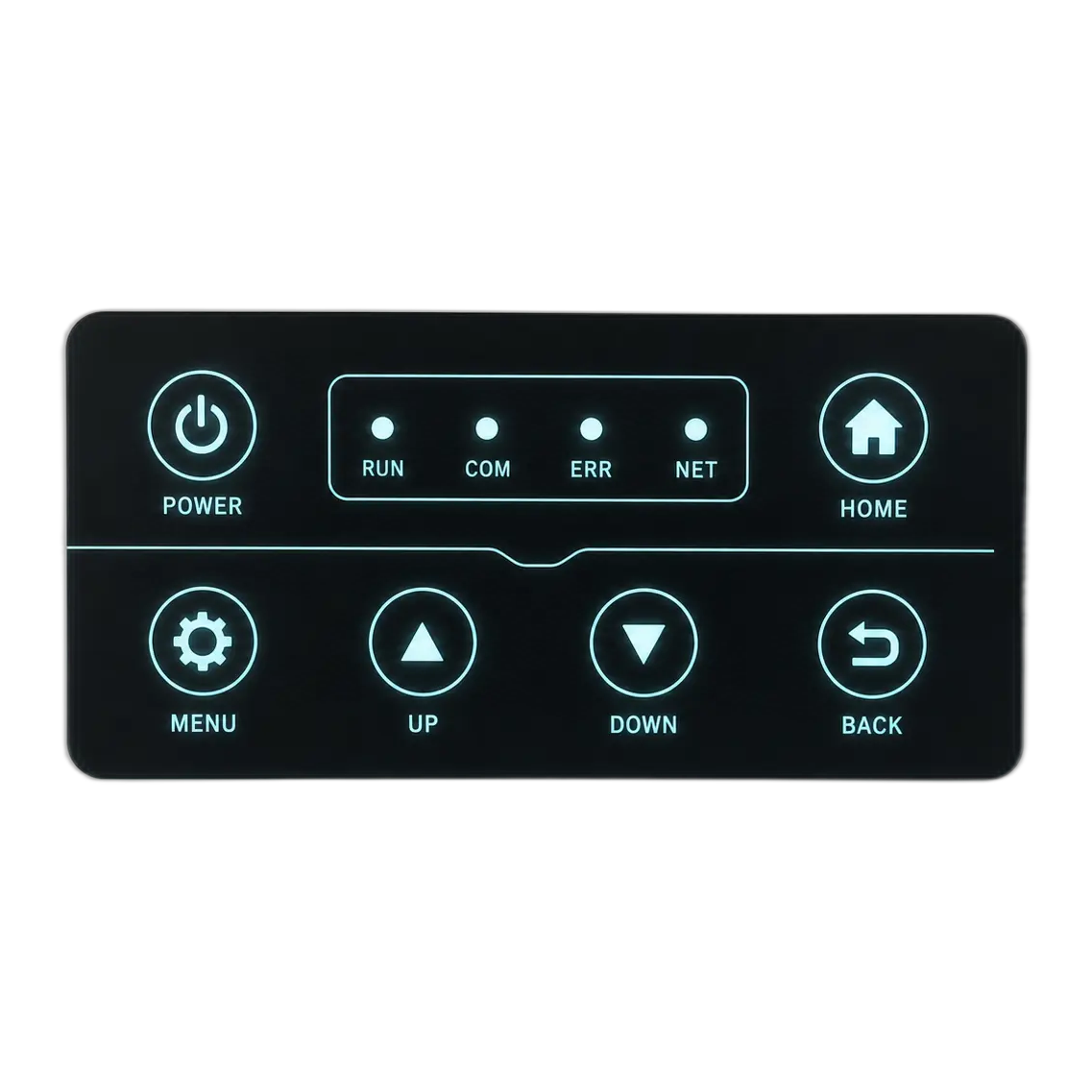
Illuminated black membrane switch panel with cyan legends and flexible tail
OFFUnpowered: controlled mask
Illuminated black membrane switch panel with cyan legends and flexible tail
ONPowered: readable icon

Approve these together

  • ghost image and pinhole inspection
  • icon-to-icon light isolation
  • edge and emboss leakage
  • off-state contrast in normal room light
  • on-state readability at the expected viewing angle

Four details decide whether the panel looks engineered.

Write the visual acceptance method into the sample plan. Words such as bright, even, or hidden are not measurable enough by themselves.

01

Uniformity

Define the illuminated zone and compare center, edge, and key-to-key appearance at the intended dimming level.

02

Light leakage

Inspect apertures, adhesive gaps, spacer edges, windows, and adjacent icons in a dark environment.

03

Dead-front contrast

Approve both powered readability and the unpowered mask under normal ambient light.

04

Power and heat

Confirm supply, current, driver, polarity, duty cycle, and enclosure heat around the optical source.

Backlighting method comparison

Use the table as a design-review starting point. Final performance depends on the approved drawing, artwork, electronics, and test environment.

MethodLight patternBest fitIntegration focusPrimary sample risk
Discrete LEDPoint or small zoneStatus and warning indicatorsPackage height, current, polarity, apertureHot spot or limited viewing angle
LED + LGFDistributed areaMulti-key legends and broad zonesEdge coupling, extraction pattern, diffuser, reflectorKey-to-key or edge-to-center variation
EL panelSoft area sourceThin, broad low-light interfaceDriver, frequency, environment, lifetime targetBrightness decay or drive mismatch
Fiber opticRemote distributed lightSpecial heat, EMI, or source-location constraintsFiber route, bend, coupling, terminationLoss, routing damage, or uneven extraction

Backlighting earns its cost when visibility changes the task.

01

Night and mobile equipment

Operators need controls and status information without flooding the environment with light.

02

Medical and laboratory systems

Selective icons and alarms must stay readable while the room or instrument lighting changes.

03

Industrial control panels

Lighting separates active functions, warnings, and machine states in enclosed or low-light work areas.

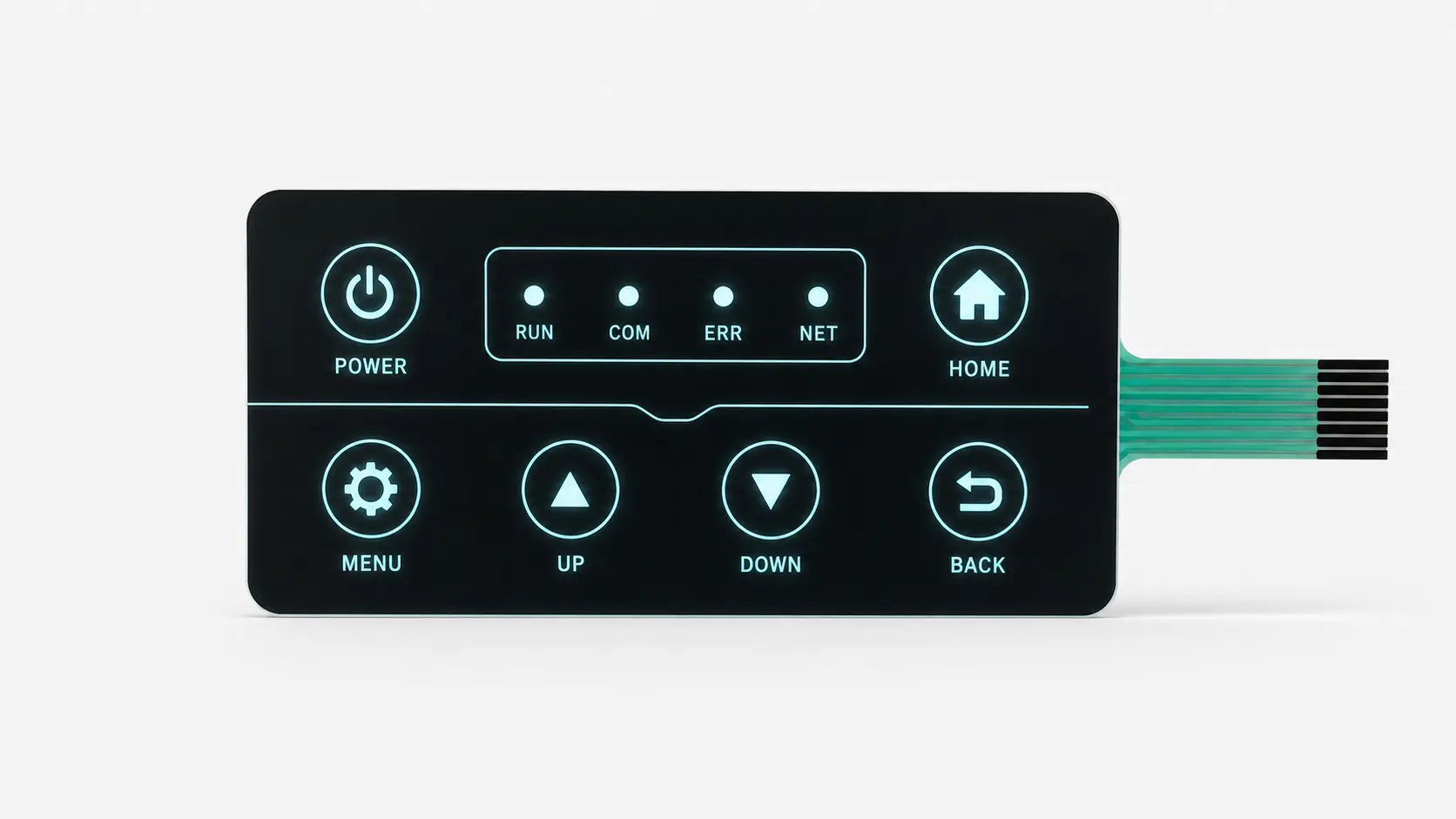
Backlit JASPER membrane switch photographed with illuminated cyan keys

Approve the sample in the real enclosure and real light.

Bench photographs can hide hot spots, crosstalk, reflections, and viewing-angle loss. Install the complete switch, run the intended controller, and inspect every lighting state.

  • normal ambient light and low-light operation
  • minimum, nominal, and maximum dimming states
  • center and worst-case viewing angles
  • adjacent icons energized separately
  • key actuation, tail fit, connector clearance, and enclosure pressure
Plan Sample Acceptance
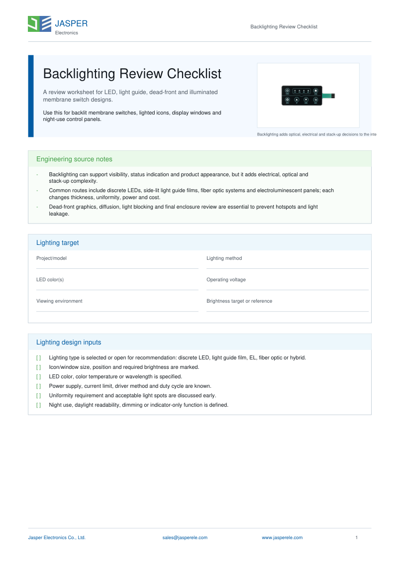
JASPER Backlighting Review Checklist cover

Backlighting Review Checklist

Prepare the lighting zones, source choice, icon artwork, off-state requirement, voltage, current, dimming, tail routing, viewing conditions, and sample acceptance criteria before tooling.

Backlit Membrane Switch FAQ

Which backlighting method is best for a membrane switch?

Use discrete LEDs for status points or small illuminated zones, a light-guide film when several keys or legends need balanced illumination, and EL when a very thin, soft area source fits the drive, lifetime, and environment. The final choice should be tested with the production artwork and enclosure.

What causes bright spots in a backlit membrane keypad?

Bright spots usually come from visible LED packages, short mixing distance, an incomplete diffuser or light-guide pattern, reflective gaps, or an aperture that exposes the source directly. Review the complete optical stack rather than changing only the ink.

How do you prevent light leakage between membrane switch icons?

Control leakage with opaque ink layers, light-blocking films, selective apertures, controlled adhesive zones, edge barriers, and enough separation between optical zones. The sample should be checked in darkness and at the intended dimming levels.

Can a backlit membrane switch use dead-front graphics?

Yes. A dead-front icon is hidden or subdued when unpowered and becomes readable when illuminated. Ink opacity, icon color, overlay texture, source brightness, and ambient light must be balanced together.

What electrical details are needed for a backlit switch quotation?

Send the supply voltage, available current, LED color or wavelength preference, polarity, resistor or driver responsibility, dimming method, connector pinout, lighting zones, and any power or heat limits.

How should an OEM approve a backlit membrane switch sample?

Approve it in the production enclosure under the actual low-light and normal ambient conditions. Check uniformity, crosstalk, off-state appearance, viewing angle, dimming range, key operation, electrical load, and appearance after the expected environmental exposure.

Continue the Backlit Membrane Switch Design Review

Send the artwork, lighting zones, and electrical limits.

JASPER can review the optical stack before the circuit and overlay are locked.

Request Backlighting Quote