
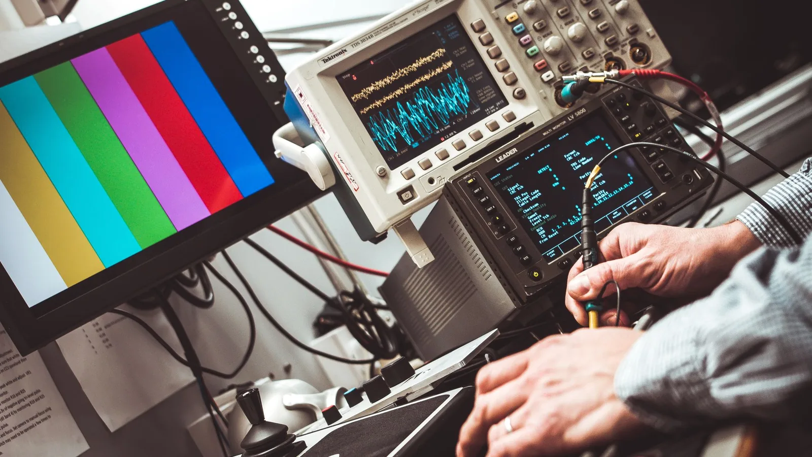
The keypad belongs to the measurement workflow
An instrumentation membrane keypad has to make readings, entry, confirmation, and service work predictable in the finished instrument. Its value is not a thin front alone; it is the controlled relationship between the operator, display, key map, circuit, enclosure, and electronics.
- 01
Read
The display window, permanent legends, indicators, and illuminated states must remain legible from the instrument's real distance, angle, and lighting.
- 02
Enter
Key size, spacing, tactile response, numeric order, navigation, and feedback must match frequent tasks without crowding the enclosure.
- 03
Confirm
The operator needs a clear response from tactile snap, display change, indicator, sound, or an agreed combination before proceeding.
- 04
Protect
Setup, calibration, reset, and service functions need deliberate placement and software control so routine operation does not expose them casually.
Start with the instrument format, not a generic keypad
Handheld meters, bench instruments, panel devices, laboratory systems, and service tools can share switch technology while demanding different viewing, handling, packaging, and approval decisions.
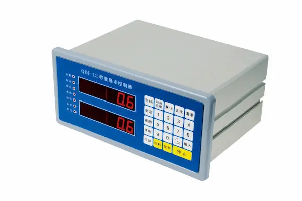
- 01
Handheld and portable meters
Portable analyzers, field meters, handheld readers, loggers, and battery-powered service tools.
- Operating pattern
- One hand may support the instrument while the thumb operates range, hold, zero, navigation, or record functions. Sunlight, dim rooms, gloves, transport, and field contamination can change what the user sees and feels.
- Interface direction
- Set grip position, thumb reach, key separation, press force, display angle, low-power indication, overlay finish, enclosure support, tail route, and connector restraint together.
- Installed approval
- Run representative standing, carried, gloved, low-light, bright-light, data-entry, and storage tasks on a production-intent housing with the real display and firmware.
- 02
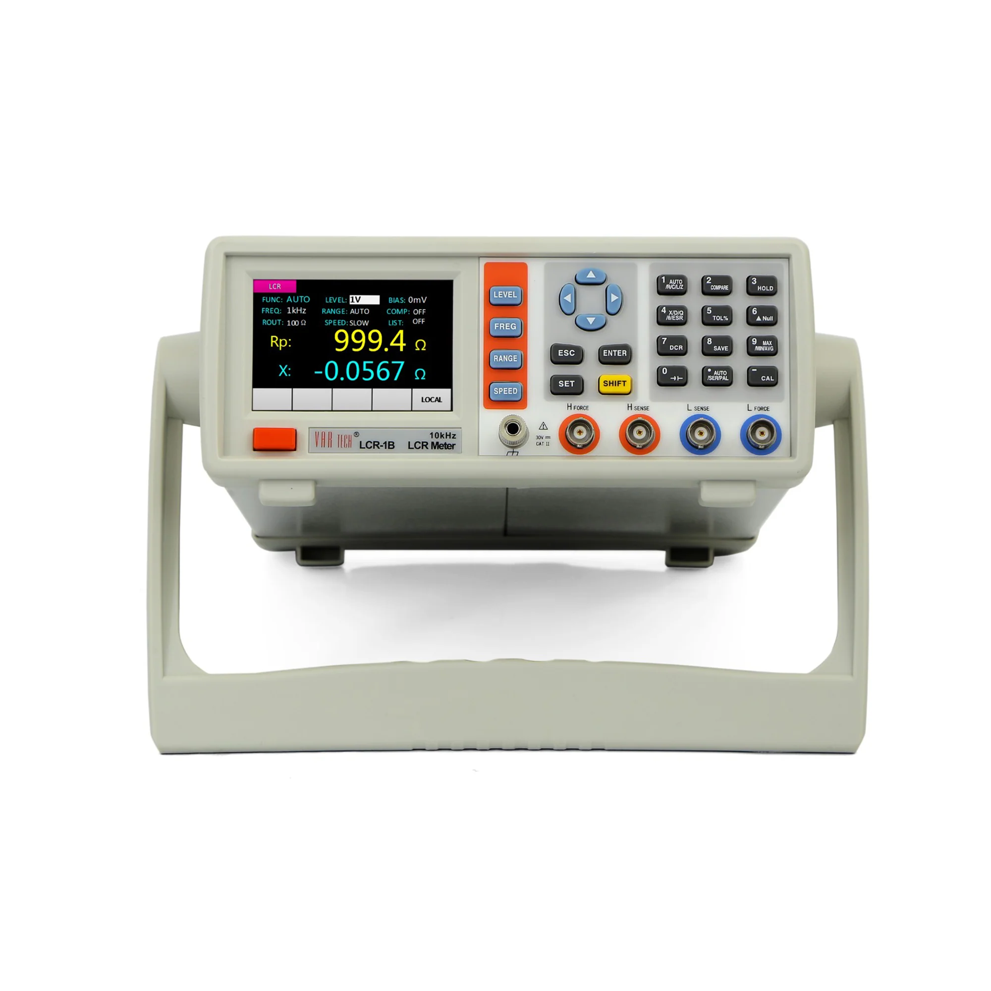
Benchtop test and measurement
Electrical test instruments, controllers, counters, power equipment, analyzers, and programmable laboratory devices.
- Operating pattern
- Dense functions, numeric entry, soft keys beside a display, repeated setup, and long viewing sessions place information hierarchy ahead of decorative symmetry.
- Interface direction
- Coordinate display active area, bezel, soft-key alignment, numeric block, frequently used controls, key grouping, tilt, anti-glare need, indicators, and front-panel service access.
- Installed approval
- Complete normal measurement setup, range changes, numeric entry, hold, review, error recovery, and powered-state inspection from intended seated and standing positions.
- 03
Laboratory and research instruments
Sample preparation systems, environmental instruments, research controllers, readers, and laboratory automation equipment.
- Operating pattern
- Users may alternate between gloves and bare hands, follow documented methods, clean around sample areas, and distinguish routine operation from maintenance or method setup.
- Interface direction
- Separate run, stop, navigation, method, cleaning, and service functions; define cleaner contact, small-legend readability, display windows, status feedback, and revision-controlled labels.
- Installed approval
- Observe representative preparation, operation, cleaning, fault, recovery, and service tasks with intended gloves, lighting, display content, software, and enclosure hardware.
- 04
Panel and process instruments
Panel meters, process indicators, transmitters, controllers, monitoring modules, and equipment-mounted instruments.
- Operating pattern
- The front can be installed at eye level, overhead, inside a cabinet, or near other controls. Operators may make infrequent but consequential changes while the unit remains powered for long periods.
- Interface direction
- Define mounting angle, access, key protection, status hierarchy, display contrast, ambient light, glove use, panel cutout, gasket or adhesive land, ground path, and cable clearance.
- Installed approval
- Inspect and operate the mounted unit from actual approach angles and under representative cabinet, plant, daylight, alarm, setup, and maintenance conditions.
- 05
Calibration and service equipment
Calibration tools, programming fixtures, maintenance terminals, commissioning devices, and depot test equipment.
- Operating pattern
- Frequent numeric entry and repeated sequences reward consistent tactile response, while protected adjustments and revision identity must remain distinct from ordinary operation.
- Interface direction
- Group repeated keys, reserve protected functions, mark sequence and units clearly, support the press area, route the tail away from service motion, and align hardware and software access control.
- Installed approval
- Perform the complete service or calibration workflow on the installed article, recording input recognition and operator feedback without assigning measurement accuracy to the keypad component.
- 06
Diagnostic and data-acquisition readers
Condition readers, recorders, data-acquisition interfaces, communication testers, and specialized electronic instruments.
- Operating pattern
- Operators move between live values, channels, stored records, connection status, warnings, and configuration. The same key can create confusion when modes are not visible.
- Interface direction
- Tie key labels, soft-key position, active mode, channel identity, indicators, display hierarchy, connector state, and software feedback into one reviewable operating map.
- Installed approval
- Exercise channel selection, data capture, review, communication, alert, disconnected, configuration, and recovery states with production display content and interface electronics.
Release the display window with the display powered
A window dimension on artwork does not establish readability. Film finish, air gap, tint, printing, adhesive, bezel overlap, display brightness, viewing angle, and room light all change the reading seen through the assembled front.
- 01
Active area and bezel
Mark the actual illuminated or readable area, inactive border, tolerance, bezel overlap, adhesive boundary, cutout, and datum used to align the window.
- 02
Finish and viewing gap
Choose clear, gloss, matte, anti-glare, or selective texture against the real separation between overlay and display; texture can soften fine characters when the gap grows.
- 03
Tint, filter, and dead front
Set unpowered appearance, display color, contrast, ambient-light need, hidden features, and any translucent print from matched off and powered samples.
- 04
Angle and lighting
Approve the instrument from its intended horizontal and vertical viewing angles in bright, normal, dim, and reflected light, not only straight on in a print room.
- 05
Indicators and leakage
Release LED position, icon registration, brightness hierarchy, diffusion, masking, hot spots, cross-light, edge leakage, and standby or alarm states with the intended drive.
- 06
Physical reference
Retain the approved overlay, display, bezel, lighting state, firmware screen, color reference, and inspection setup as one release set for future production comparison.
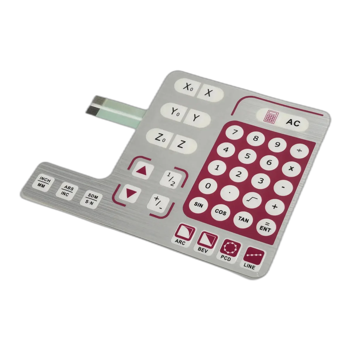
Give frequent actions the clearest physical language
A compact keypad works when the user can find, press, and confirm the correct function without rereading the whole panel. Key geometry and feedback follow task frequency, consequence, reach, and software response.
Primary operation
Measure, start, stop, hold, zero, range, record, or another routine action needs a stable location, strong label, adequate target, and unmistakable response.
Numeric and navigation
Number order, decimal, sign, unit, arrows, enter, escape, and correction should match the screen flow and support fast entry without accidental adjacent presses.
Mode and secondary functions
Shifted functions, channel changes, menus, and soft keys need visible mode feedback. Color alone should not carry the entire distinction.
Setup and service
Calibration, reset, communication, test, or protected adjustment functions belong in a deliberate access path supported by firmware and the instrument's service policy.
- named users, gloves, dominant hand, reach, viewing position, and press technique
- key center, target size, spacing, emboss, dome geometry, support, and actuation force
- tactile, visual, audible, and software confirmation for each operating state
- high-frequency sequences, simultaneous or held input, debounce, lockout, and error recovery
Choose the circuit route around density and packaging
The face can look identical over different electrical backbones. The useful choice follows trace density, tail route, components, support, connector, power, shield, assembly, service, and production volume.
Printed PET circuit
A low-profile printed circuit can suit straightforward low-voltage key matrices and compact tails. Release trace layout, spacer venting, contact geometry, tail, termination, environmental boundary, and electrical checks for the actual design.
Copper FPC circuit
Copper FPC supports finer routing and different interconnect options where density or packaging requires it. Define copper, coverlay, stiffener, bend zones, connector, shielding, assembly motion, and whether any bend is static or dynamic.
PCB-backed keypad
A rigid PCB can support domes, LEDs, components, connectors, and the key area while simplifying attachment to instrument electronics. Board thickness, component keep-outs, fasteners, display support, and enclosure stack become part of the keypad release.
Integrated HMI assembly
A membrane keypad can be supplied with overlay, circuit, PCB or FPC, LEDs, display window, carrier, connector, gasket, or housing work when the interface boundary and test responsibility are explicitly divided.
Send the current package with open decisions marked for an instrumentation keypad review.
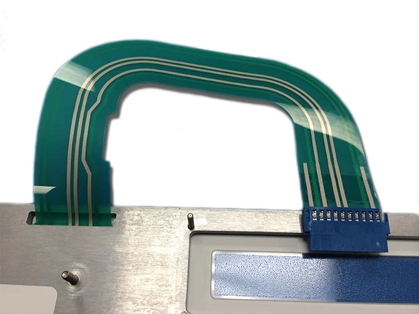
Treat the tail path as mechanical packaging
A tail that works on a flat drawing can be damaged, trapped, reversed, or misconnected during assembly. The released route starts at the keypad edge and ends at a restrained, serviceable interconnect.
- 01
Exit position
Choose edge or inset exit around active keys, windows, circuit routing, perimeter land, housing slots, bezel coverage, and assembly direction.
- 02
Static bend route
Define bend location, radius, orientation, forming method, clearance, and support from the selected circuit construction and supplier drawing.
- 03
Connector interface
Release connector family, contact side, pitch, pin count, pin-one reference, insertion direction, latch, mating cycles, and board location.
- 04
Stiffener and restraint
Set stiffener geometry, transition support, strain relief, harness retention, and clearance from sharp edges, heat, fans, hinges, fasteners, and service tools.
- 05
Assembly access
Document liner removal, keypad placement, tail insertion, connector closure, visual confirmation, rework limit, and the fixture or datum used by production.
- 06
Service boundary
Decide whether the keypad, front panel, cable, or HMI is replaceable and prevent a service procedure from repeatedly flexing a tail designed for static installation.
Keep interface protection separate from measurement claims
A membrane keypad can include shielding and controlled circuits, but instrument accuracy and immunity emerge from the complete electronics, enclosure, grounding, firmware, layout, and validation plan.
The component boundary is part of the specification.
- 01
ESD path
Define the discharge points, shield type, coverage, edge clearance, ground tab or tail, mating location, enclosure relationship, and complete-instrument test method.
- 02
EMI and RFI boundary
State the suspected source, frequency or operating condition, shield and cable route, ground reference, nearby circuitry, display opening, and system acceptance criteria.
- 03
Key scanning and debounce
The keypad supplies contacts and a pinout; the instrument electronics and firmware own scanning, pull-ups, debounce, long press, simultaneous input, wake behavior, and fault handling.
- 04
Measurement and calibration
The OEM owns sensor excitation, analog path, references, conversion, algorithms, calibration, uncertainty, traceability, and accuracy statements. Keypad production does not establish these results.
- 05
System verification
Test the production-intent keypad in the complete powered instrument through normal, fault, communication, environmental, ESD/EMC where required, and recovery states using OEM acceptance criteria.
Release the installed instrument, not a loose keypad
A loose part confirms artwork and basic switching. It cannot confirm display readability, bezel alignment, key support, tail clearance, grounding, firmware feedback, connector access, or the complete task.
- 01
Visual states
Inspect unpowered, startup, normal, hold, entry, alert, communication, service, and dim or bright states with the real display, LEDs, bezel, and viewing positions.
- 02
Operator tasks
Complete the highest-frequency and highest-consequence sequences with intended users, gloves, hand position, feedback, timing, error recovery, and protected functions.
- 03
Mechanical and electrical fit
Check housing support, adhesive, window alignment, tail route, connector, strain relief, ground path, cable access, assembly sequence, and service motion.
- 04
Release evidence
Record artwork, materials, key map, pinout, display reference, lighting states, dimensions, circuit route, test limits, approved sample, revision, and OEM-owned system validation.
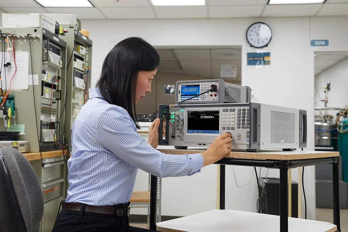

Production evidence tied to the instrument revision
JASPER builds the released keypad or agreed interface assembly and records the checks named by its drawing and control plan. Evidence stays linked to the correct artwork, circuit, key map, connector, option, and revision.
- Identity
- Released artwork, materials, dimensions, circuit master, key map, pinout, connector, variant, revision, and approved sample.
- Appearance
- Print registration, legends, finish, windows, indicators, color reference, cutouts, emboss, and assembly condition where specified.
- Electrical
- Project-defined continuity, open/short, key map, contact, LED polarity or function, tail, connector, and other agreed checks.
- Mechanical
- Outline, datums, window and key location, tail and stiffener, adhesive condition, laminate alignment, and packaging protection.
The instrument OEM remains responsible for intended use, user workflow, measurement method, calibration, accuracy, uncertainty, sensor and analog design, software, safety, EMC and ESD system performance, environmental rating, complete-product certification, service policy, and finished-instrument validation.
Match the interface route to the instrument package
Product directions
Custom key layouts, tactile or non-tactile feedback, printed legends, windows, tails, connectors, and project-defined inspection.
Rigid or flexible circuit routes for dense interconnect, components, support, shielding, and enclosure integration.
Indicators, illuminated icons, light guides, dead-front states, masking, diffusion, and powered-sample approval.
Keypad, display window, PCB or FPC, carrier, connector, gasket, and agreed assembly or functional test scope.
Engineering resources
Review overlay, keys, windows, circuit, adhesive, tail, connector, and enclosure inputs before release.
Define LEDs, light guides, diffusion, dead-front masking, brightness, leakage, and matched powered states.
Coordinate exit, bend, stiffener, connector, contact side, strain relief, assembly, and service route.
Package drawings, artwork, key map, pinout, display, materials, environment, quantity, and approval evidence.
Send the instrument interface package
A useful quotation shows how the operator uses the instrument and how the keypad fits its display, housing, electronics, and release plan. Mark open decisions rather than guessing them into the drawing.
Open Instrumentation Keypad Form- 01instrument type, users, operating tasks, key frequency, protected functions, gloves, viewing position, and environment
- 02front-panel, bezel, display, active area, housing, mounting, support, cutout, clearance, and assembly drawings
- 03key map, tactile or non-tactile response, target force, emboss, feedback, LEDs, backlighting, and operating states
- 04overlay film, finish, artwork, color reference, legends, units, language, windows, tint, dead-front, and variants
- 05PET, copper FPC, or PCB preference; schematic, matrix, pinout, electrical limits, shield, and grounding concept
- 06tail exit, length, bend route, stiffener, connector, pitch, contact side, latch, board position, and service access
- 07prototype quantity, annual estimate by variant, sample deadline, qualification plan, inspection records, labeling, and packaging
Instrumentation Membrane Keypad FAQ
What makes a membrane keypad suitable for test and measurement instruments?
A suitable instrumentation keypad is designed around the real operator workflow, display, key frequency, tactile or visual feedback, circuit, tail, connector, enclosure support, environment, and inspection plan. The same front artwork can perform differently when the display gap, key support, firmware response, or tail route changes, so approval uses a production-intent installed sample.
Should an instrument membrane keypad use tactile or non-tactile keys?
Use tactile keys when physical confirmation helps frequent entry, gloved work, eyes-on-display operation, or consequential commands. Non-tactile zones can suit large targets or instruments that provide immediate visual or audible feedback. Mixed panels are possible. Release the decision with intended users, support surface, dome or contact construction, force, feedback, and representative task testing.
How should a display window be specified in a membrane keypad?
Specify the display active area, inactive border, bezel overlap, viewing gap, overlay finish, clear or tinted zone, adhesive boundary, cutout, registration datum, viewing angles, ambient light, powered brightness, indicators, leakage limits, and acceptance states. Approve it with the intended display, firmware screen, bezel, LEDs, and enclosure rather than from an artwork PDF alone.
When should an instrumentation keypad use PET, copper FPC, or a PCB backing?
Printed PET suits many low-profile switch matrices. Copper FPC can support finer routing and different connector or packaging needs. A PCB backing can add rigidity, domes, components, LEDs, and direct interconnect. Choose from trace density, electrical limits, bend route, support, component keep-outs, connector, shielding, assembly, service, volume, and the OEM electronics architecture.
Can ESD shielding in the membrane keypad protect measurement accuracy?
A shield layer can contribute to a defined discharge path, but it does not by itself establish instrument immunity or measurement accuracy. Coverage, edge clearance, grounding, tail, connector, display opening, enclosure, PCB layout, cables, firmware, analog design, and the complete test method all matter. The instrument OEM validates ESD, EMC, signal integrity, calibration, uncertainty, and accuracy.
What files are needed to quote a custom instrumentation membrane keypad?
Send the front-panel and housing drawing, artwork, display active area, key map, tactile requirement, circuit or pinout, tail exit and route, connector, material and finish, windows, LEDs or backlighting, shielding concept, operating environment, sample quantity, annual quantity by variant, target schedule, and qualification or inspection requirements. Early CAD and marked open decisions are suitable for review.