Dongguan, Guangdong 523927, China[email protected]+86 136 3262 5290
Home / Products / Medical Electrode Pads / Custom Wearable Biosensor Patches
FLEXIBLE PRINTED SENSING CIRCUITS FOR OEM WEARABLES

Custom Wearable Biosensor Patches

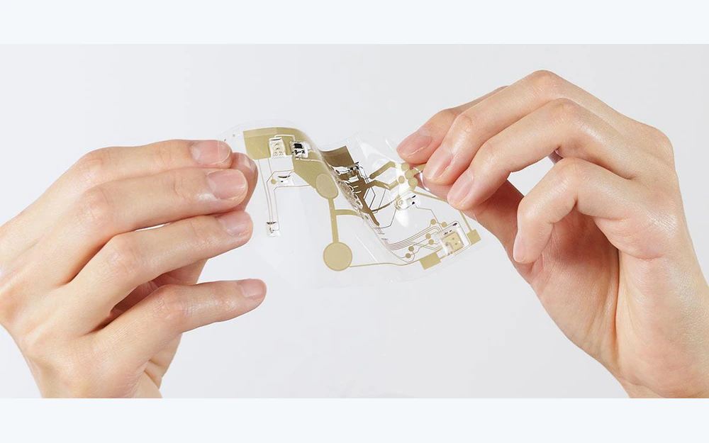
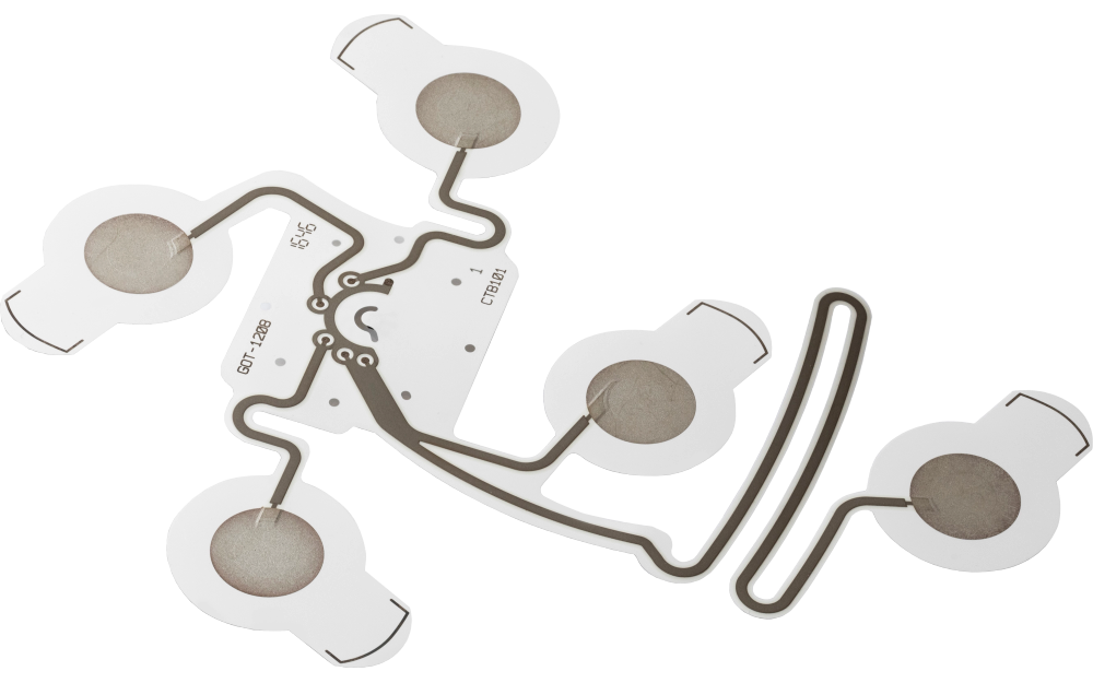
Custom wearable biosensor patch with printed sites flexible traces and electronics island

Custom wearable biosensor patches combine printed sensing sites and flexible interconnect with the mechanical body that the OEM integrates into its electronics platform. JASPER can manufacture printed traces, dielectric, component or connector lands, tails, reinforcement, backing, project-specified adhesive or hydrogel zones, liners, labels, die cuts, packaging, and agreed inspection. Electronics, firmware, algorithms, wear studies, clinical claims, and finished-device validation remain with the OEM.

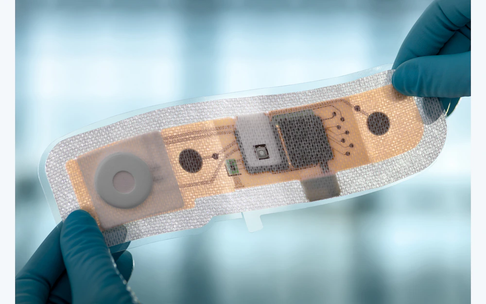
Custom wearable biosensor patch with printed sites flexible traces and electronics island
Printed sensing circuitsites, traces, dielectric, component lands, tail, connector, and reference geometry
Wearable mechanical bodyflex zones, reinforcement, backing, adhesive zones, liner, die cut, and package
OEM intelligence retainedelectronics, firmware, algorithms, wireless, power, wear, clinical use, and compliance

The Patch Circuit and the Wearable Device Are Different Release Boundaries

JASPER can supply a passive printed sensing circuit, a converted patch body, or an agreed assembly with selected customer-specified components. The BOM must state what is printed, mounted, connected, laminated, die cut, inspected, and packaged.

A patch that fits the body and passes continuity is not yet a validated wearable. The OEM owns power, electronics, firmware, communications, algorithms, data interpretation, environmental behavior, wear, biocompatibility, clinical use, cybersecurity, and regulatory approval.

Custom Wearable Biosensor Patches fit when:

  • printed sensing sites and flexible routing must follow a custom wearable geometry
  • component, connector, or tail lands require registered reinforcement and strain management
  • backing, adhesive or hydrogel zones, liner, labels, die cut, and package can be released by project
  • the OEM owns electronics, software, algorithms, communications, wear, clinical, security, and regulatory validation

Six Controls Separate the Flexible Patch from the Complete Wearable

The responsibility matrix should follow data and power from the sensing site to the OEM host.

01

Sensing-site geometry

Release control

Release site size, position, reference geometry, contact opening, orientation, body datum, and non-sensing zones.

If it is missing

The patch fits mechanically while the sensing geometry differs from the OEM evaluation.

02

Printed routing and dielectric

Release control

Define traces, widths, clearances, crossovers, dielectric, flex zones, resistance, continuity, isolation, and registration.

If it is missing

Repeated flex or conversion exposes or damages conductors.

03

Electronics and connector lands

Release control

Name component pads, connector, tail, pin map, surface finish, reinforcement, attachment, and supplied or excluded parts.

If it is missing

The circuit image implies electronics that are not controlled in the BOM or test scope.

04

Strain and flexibility

Release control

Map rigid islands, reinforced transitions, bend paths, adhesive-free hinges, cable exits, and package supports.

If it is missing

Stiffness concentrates at a trace or connector transition.

05

Wearable material zones

Release control

Release backing, adhesive or hydrogel, foam or nonwoven, liner, breathable or non-contact areas, labels, and edge margins.

If it is missing

Converted materials shift site exposure or flexible behavior.

06

Inspection and OEM handoff

Release control

Define print, dimensions, electrical tests, component or connector checks, flex sample, labels, package, and excluded device tests.

If it is missing

A patch-level check is mistaken for validation of electronics, algorithm, wear, or clinical outcome.

Release the Wearable Patch by Circuit, Mechanical Zone, and Data Owner

Each layer and interface should have a named supplier, test, and downstream validation owner.

BoundaryOptions to ReviewRelease Question
Sensing frontElectrode sites, reference sites, openings, orientation, body datum, graphics, non-sensing and handling zonesWhich contact geometry belongs to the supplied patch?
Flexible circuitInk, substrate, traces, dielectric, flex zones, component lands, tail, connector lands, resistance, continuity, and isolationWhat electrical state exists before OEM electronics are connected?
Components and interfaceBare lands, selected components, connector, tail, FPC, reinforcement, pin map, attachment, and programming boundaryWhich parts arrive installed and what remains OEM-supplied?
Converted bodyBacking, adhesive or hydrogel zones, foam or nonwoven, rigid islands, flex hinges, liner, label, and die cutHow is the mechanical patch body registered to the circuit?
Patch evidenceAppearance, dimensions, registration, continuity, resistance, isolation, component or connector check, flex sample, label, and packWhich checks prove the supplied patch only?
OEM device validationPower, battery, wireless, firmware, algorithms, data, wear, environment, biocompatibility, clinical use, security, and complianceWhich outcomes remain with the complete wearable program?
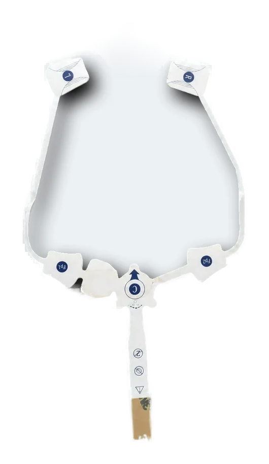
Wearable printed electrode patch showing sensing sites flexible traces and tail routing
FLEXIBLE CIRCUIT ARCHITECTURE

Route Sensing Sites to a Stable Electronics Handoff

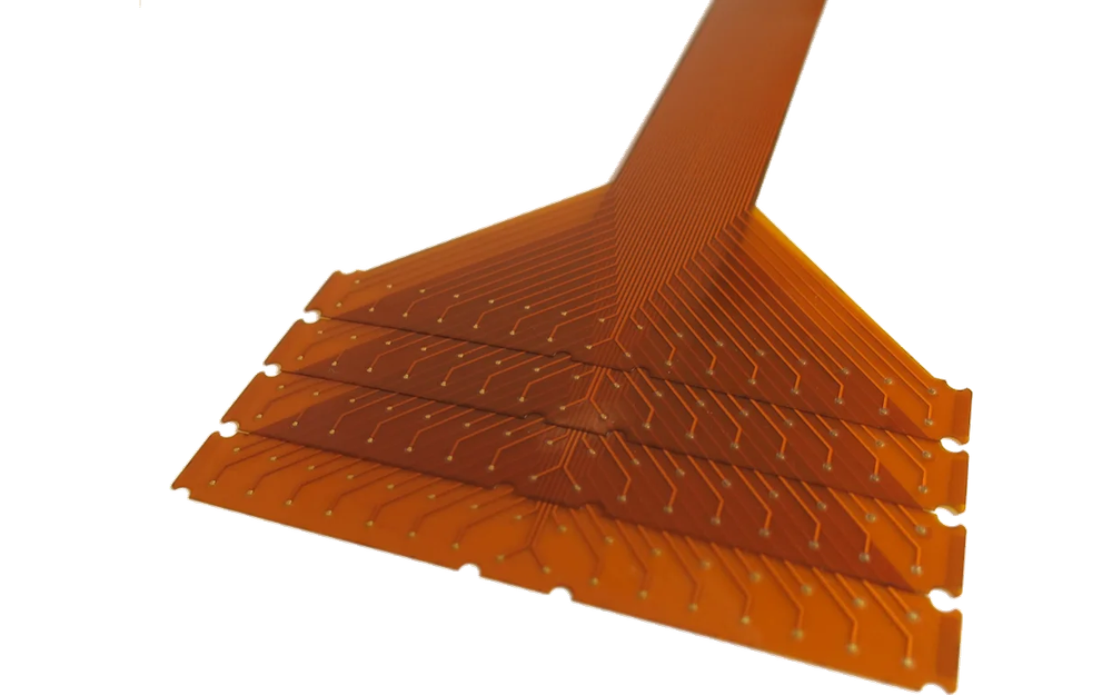
Trace density, dielectric, rigid islands, component lands, tail exit, connector reinforcement, bend direction, and adhesive-free hinges should be resolved in the same mechanical model. The best route is the one the converted patch can support repeatably.

  • separate sensing, flexible, reinforced, and connector zones
  • release tail and pin map with the circuit master
  • identify supplied components and configuration explicitly
  • inspect the patch before OEM electronics and algorithms are evaluated
Exploded converted layer stack for a custom wearable biosensor patch
CONVERTED WEARABLE STACK

Close Layer Overlaps Around Sites, Rigid Islands, and Flex Hinges

Backing, adhesive or hydrogel, reinforcement, liner, labels, component protection, and package supports can alter flexibility. The stack drawing should show where each material starts and stops instead of listing one overall material set.

  • map every material zone and overlap
  • keep bend transitions clear of unplanned stiffness
  • approve liner removal and handling with the production sample
  • assign wear and environmental validation to the OEM

Move from Printed Geometry to a Controlled OEM Handoff

01

Define the wearable boundary

Release sensing role, electronics handoff, body location, mechanical zones, environment, and OEM-owned validation.

02

Route the flexible circuit

Close sites, traces, dielectric, component or connector lands, tail, pin map, bend zones, and electrical tests.

03

Build the converted body

Release backing, adhesive or hydrogel zones, reinforcement, rigid islands, flex hinges, liner, labels, and die cut.

04

Approve patch samples

Review geometry, electrical checks, connector or component state, flexibility, liner, handling, labels, and package.

05

Control repeat builds

Lock artwork, materials, parts, processes, fixtures, records, packaging, substitutions, and requalification triggers.

Locate Wearable Patch Problems by Layer and Owner

01

Trace fails near a rigid island

Review bend direction, reinforcement edge, dielectric, trace geometry, adhesive overlap, connector load, and package support.

02

Sensing site shifts after converting

Check circuit datum, material zones, lamination, die cut, liner, stretch, fixture, and handling method.

03

Connector or component state varies

Compare part source, land geometry, attachment, reinforcement, orientation, pin map, inspection, and BOM revision.

04

Patch passes but wearable output fails

Separate patch evidence from power, electronics, firmware, wireless, algorithms, environment, wear, body placement, data interpretation, and complete-device validation.

Where Custom Wearable Biosensor Patch Manufacturing Fits

01

Physiological monitoring platforms

Printed sensing circuits and converted patch bodies supplied to OEM electronics and algorithm programs.

02

Connected health research

Flexible patch prototypes used with customer-owned wireless, data, and study systems.

03

Sports and biomechanics wearables

Custom sensing-site geometry, flexible routing, and connector handoff for OEM validation.

04

Industrial worker monitoring concepts

Printed wearable circuits integrated into customer-controlled environmental and safety programs.

05

Laboratory wearable instruments

Application-specific arrays and component lands supplied to research electronics.

06

Disposable sensor front ends

Printed and converted patch bodies delivered to an OEM reusable electronics architecture.

RFQ PACKAGE

Send the Sensing Map, Electronics Handoff, and Wearable Zone Drawing

A useful RFQ separates the passive patch, optional installed parts, and complete wearable validation.

  • sensing-site and reference geometry, orientation, body datum, contact openings, non-sensing zones, and placement relationship
  • conductive ink, substrate, traces, dielectric, flex zones, component or connector lands, tail, continuity, resistance, and isolation
  • components, connector, pin map, attachment, reinforcement, bend keep-outs, cable or host interface, and supplied or excluded state
  • backing, adhesive or hydrogel zones, foam or nonwoven, rigid islands, flex hinges, liner, labels, and edge margins
  • outside die cut, openings, registration, electrical and mechanical inspection, flex sample, handling, package, and traceability
  • prototype quantity, annual estimate, storage and shipment, change control, and OEM electronics, algorithm, wear, clinical, security, and regulatory validation
Send Wearable Patch Files

Custom Wearable Biosensor Patches FAQ

Can JASPER manufacture passive printed wearable sensor patches?

Yes, with released sensing geometry, traces, dielectric, tail or connector lands, converted materials, die cut, electrical inspection, packaging, and OEM validation boundary.

Can components or connectors be included?

Selected parts can be included when the exact BOM, source, land pattern, attachment, configuration, reinforcement, inspection, lifecycle, and replacement rule are released.

Does JASPER provide firmware or biosensor algorithms?

Not by default. Electronics, firmware, wireless, algorithms, data interpretation, application software, clinical logic, cybersecurity, and finished-device validation remain with the OEM unless separately contracted.

Can the patch include adhesive-free flex hinges?

Yes. Their geometry, surrounding traces, dielectric, reinforcement edges, backing, liner, bend direction, inspection, and package support should be released in the stack drawing.

Does a flexible patch sample prove wear duration?

No. Patch manufacturing checks do not establish wear duration, body compatibility, sweat or motion performance, data quality, clinical outcome, or regulatory approval. The OEM must validate those conditions.

Related Electrode and Printed Circuit Routes

Release the sensing circuit, flex zones, electronics handoff, and wearable stack together.

JASPER can review printed sites, traces, dielectric, component or connector lands, tail, converted layers, die cutting, inspection, packaging, and change control.

Start Wearable Patch ReviewContact Engineering