
Press the defined key zone
Graphics or embossing make the active area obvious.
Flat, quiet OEM interfaces that register the press without a metal dome. JASPER engineers key geometry, spacer gap, printed contacts, feedback cues, tail, adhesive, and enclosure support as one assembly.
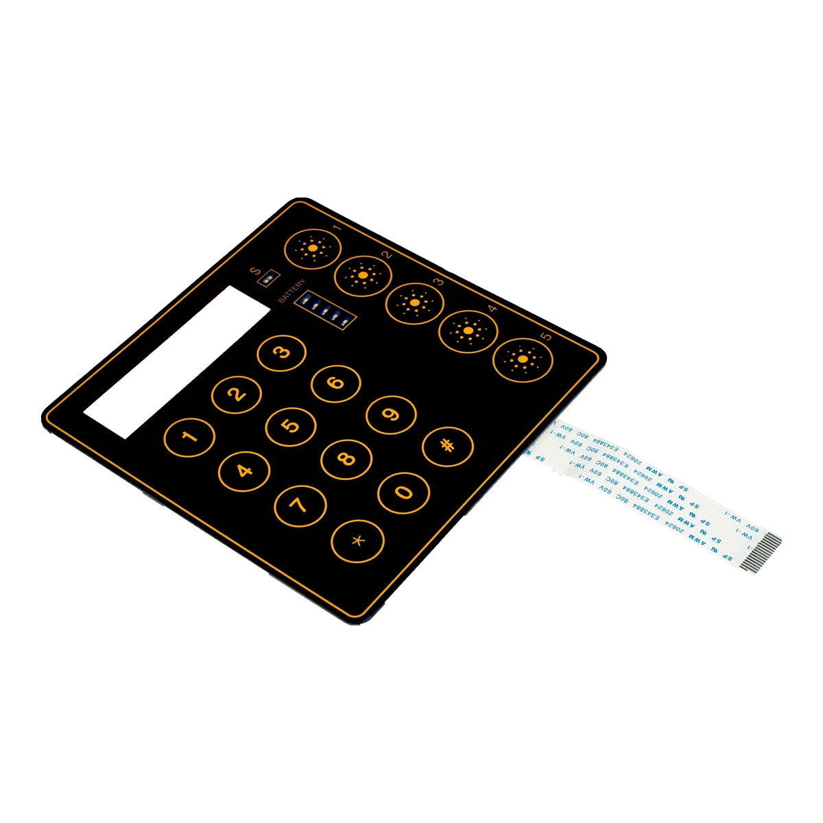
Non-tactile construction removes the dome snap, not the need for a deliberate user experience. Validate the full signal path inside the real equipment.
Graphics or embossing make the active area obvious.
Travel and venting control how the panel moves.
Pad geometry and support surface stabilize the input.
LED, display, tone, or software closes the feedback loop.
The strongest applications already provide visual or electronic confirmation and benefit from a sealed, low-profile control surface.
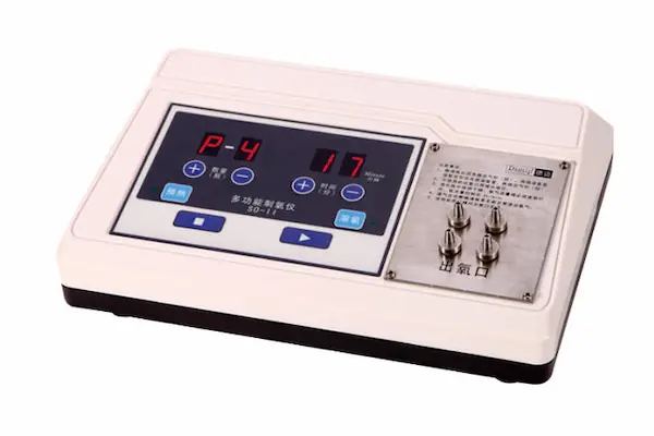
Easy-clean control surfaces with screen or audible confirmation in quiet working environments.
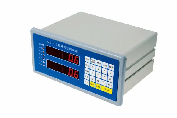
Broad function areas beside displays that show the command immediately after input.
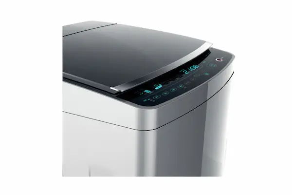
Flat front panels where lighting and digital status feedback carry the interaction.
Without a dome snap, spacer geometry and system feedback become part of the control logic.
Review the switch inside the actual enclosure with the production overlay, adhesive, connector, and controller.
Use print, rim embossing, pillow embossing, or a shaped bezel to guide the finger.
Large keys and wide panels need repeatable air movement and spacer relief.
Specify LED, display, sound, or firmware response before sample approval.
Verify the operator can actuate the key across the usable press area.
Use the first sample to lock the installed behavior, not only the loose switch dimensions.
| Design variable | Drawing or RFQ decision | Sample acceptance |
|---|---|---|
| Key boundary | Printed zone, rim emboss, pillow emboss, or bezel | Operator finds the active area without guessing |
| Spacer and vent path | Gap, relief geometry, and air path around each key | Center and edge presses close and release consistently |
| Printed contacts | Pad size, overlap, routing, and matrix assignment | Stable input without intermittent closure |
| System feedback | LED, display, sound, or software response | User receives an immediate and unambiguous confirmation |
| Support surface | Enclosure flatness, cutouts, ribs, and adhesive land | Bonded switch behaves like the approved loose sample |
| Tail and connector | Exit direction, bend radius, pinout, and clearance | Installed cable reaches without stress or interference |
| Environment | Cleaning agents, moisture, abrasion, and temperature | Overlay, printing, and adhesive remain acceptable |
Production tip: Approve the bonded switch through the real controller because software timing and physical release are part of the user experience.
Choose the feedback method around the operator and equipment workflow, not around a preferred component.

Loose films and bench continuity are not enough. Bond the sample to the intended support surface and exercise it through the real controller.
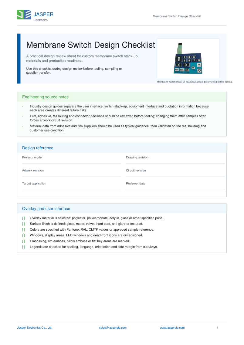
Prepare the key map, feedback method, circuit pinout, spacer venting, tail route, connector, support surface, and sample acceptance method before tooling.
The printed contacts close electrically, while the equipment confirms the input through an LED, display change, tone, or software response. The confirmation method should be included in sample testing.
Yes. Rim or pillow embossing can identify the active area and guide the finger without adding a metal-dome snap. Emboss geometry must still match the spacer and support surface.
Common causes include trapped air, an uncontrolled spacer gap, limited support beneath the key, contact geometry, or an operator pressing outside the reliable active area.
A tactile switch is usually stronger when the operator needs physical confirmation, works with gloves, presses keys without watching the display, or expects a distinct snap point.
Send the outline, key map, feedback method, circuit or pinout, tail and connector, enclosure support surface, environment, quantity, and sample acceptance criteria.
Compare operator feedback, use cases, and sample-review priorities.
Read GuideReview printed contacts, matrix routing, tail pinout, and test access.
Read GuidePrepare the drawing, environment, quantity, feedback, and approval inputs.
Read GuideJASPER can review the complete input path before tooling.
Share the project basics. JASPER will review the stack, materials, connector, quantity, and production risks.