Dongguan, Guangdong 523927, China[email protected]+86 136 3262 5290
Home / Products / HMI Assembly / PCB and FPC HMI Assemblies
ELECTRONICS-LED OPERATOR ASSEMBLIES

PCB and FPC HMI Assemblies

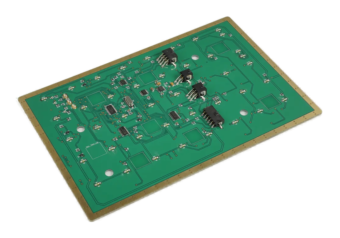
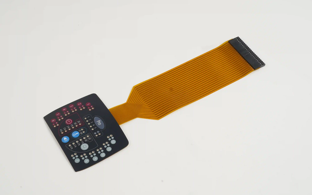
A PCB and FPC HMI assembly coordinates the operator front with rigid and flexible electronics, components, lighting, display or indicators, internal interconnects, connectors, mechanical support, test access, and a released output state. It is not merely a PCB build or a membrane circuit; the product is the assembled interface delivered to the OEM.

PCB and FPC HMI assembly with front controls, rigid board, flexible circuit, components, carrier, and connector
Electronics integratedfront inputs, PCB, FPC, components, LEDs, display interface, cables, and connectors
Mechanical support alignedboard datums, flex bends, keep-outs, carrier, fasteners, front stack, and rear clearance
Output state releasedpinout, power, programming boundary, diagnostics, fixture, records, and customer handoff

The Assembly Owns the Interface Between Electronics and Operator Front

A PCB or FPC membrane switch page explains one input-circuit construction. This route is broader: it combines the front control technology with rigid and flexible electronics, selected components, display or indicators, internal cables, rear support, connectors, and assembly-level test evidence.

Mechanical and electrical drawings must agree on board origin, flex exit, connector orientation, component height, keep-outs, mounting holes, display relationship, grounding, and service path. A correct schematic does not guarantee an installable operator module.

Programming, calibration, controller files, communication checks, and higher-level function tests are included only when the released scope names the hardware, software owner, fixture, input data, expected output, and configuration record.

PCB and FPC HMI Assemblies fit when:

  • the customer wants front controls, PCB or FPC electronics, components, connectors, and mounting delivered as one module
  • rigid-flex routing, board support, display or indicator interfaces, and rear clearance need one integration owner
  • the connector output, programming state, diagnostics, and production test boundary can be released
  • the OEM retains complete application, machine, safety, field-wiring, and regulatory validation

Six Controls for an Electronics-Led HMI Assembly

The assembly should connect circuit intent to the physical front, rear structure, firmware boundary, and production fixture.

01

Architecture and board split

Release control

Define rigid PCB, FPC, membrane circuit, daughterboard, cable, connector, display, input technology, and the purpose of each interface.

If it is missing

Functions or signals are duplicated, omitted, or assigned to the wrong circuit layer.

02

Files, BOM, and sources

Release control

Release schematic, Gerber or fabrication data, pick-and-place, BOM, approved parts, substitutes, programming files, and revision links.

If it is missing

The board builds but does not match the approved component, firmware, or supply configuration.

03

Mechanical board integration

Release control

Control origins, holes, thickness, component height, keep-outs, flex bends, connector access, support, carrier, fasteners, and rear clearance.

If it is missing

The electronics pass bench test but collide, flex, or become inaccessible in the HMI module.

04

Front-input interface

Release control

Release membrane, silicone, capacitive, encoder, indicator, display, contact, electrode, light, and connector relationships.

If it is missing

The board is electrically correct while the operator input or visible feedback is misaligned.

05

Power, signal, and ground

Release control

Define rails, current assumptions, pinout, communication, ground and shield, ESD path, startup, fault, diagnostics, and customer host.

If it is missing

The assembly operates in the fixture but becomes unstable with the customer's power or enclosure ground.

06

Programming and test boundary

Release control

Name programming method, files, identifiers, continuity, component, input, lighting, display, communication, fixture, records, and excluded system tests.

If it is missing

A programmed board or basic function check is mistaken for final application approval.

Release PCB and FPC HMI Responsibility from Source Files to Connector Output

A controlled module links electronics revision, mechanical assembly, programmed state, test evidence, and the customer interface.

DecisionOptions to ReviewRelease Question
Circuit architectureRigid PCB, FPC, printed membrane circuit, rigid-flex, daughterboard, cable, connector, display, lighting, and input technologiesWhich circuit owns each function and interface?
Fabrication and assemblyMaterials, copper, finish, stack, components, soldering, adhesives, stiffeners, strain relief, cleaning, and conformal coatingWhich manufacturing and assembly processes are included?
Mechanical integrationBoard datum, holes, thickness, component keep-outs, flex bend, connector access, carrier, fasteners, front stack, and rear clearanceHow are circuits supported and accessed inside the operator module?
Software and configurationBootloader, firmware, controller file, calibration, identifiers, version marking, loading, storage, and ownershipWhat programmed or unprogrammed state is delivered?
Customer interfacePower, pinout, communication, ground, shield, display or host connection, diagnostics, startup, disabled, and fault statesWhat signals and behavior exist at the customer connector?
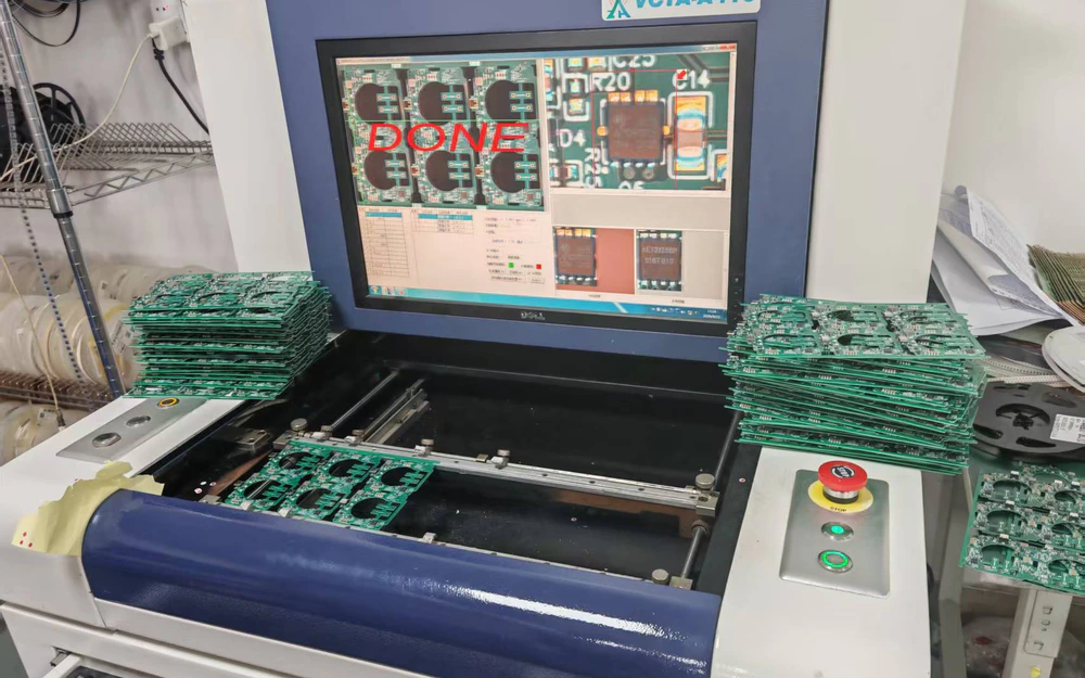
Production evidenceAOI, electrical test, continuity, programming verify, input, LEDs, display, communication, fixture, records, traceability, and packagingWhich evidence proves the module and which remains customer system validation?
PCB and FPC HMI module with highlighted rigid-flex route, mounting datums, and customer connector
RIGID-FLEX GEOMETRY

Route the Circuit Through the Real Mechanical Assembly

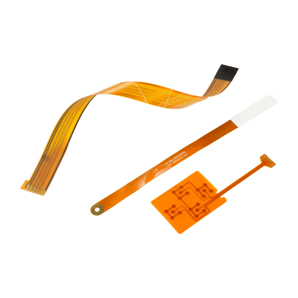
FPC bend radius, stiffener edge, connector height, component keep-out, board support, fastener position, display bracket, and enclosure ribs determine whether the electrical design can survive installation and service.

  • model flex bends and connector access in the customer installation direction
  • support boards around connectors, keys, displays, and high insertion loads
  • separate component keep-outs from nominal free space
  • protect exposed circuits and connectors during assembly and shipment
PCB and FPC HMI assembly in a fixture for programming, electrical, input, and connector checks
PROGRAMMED HANDOFF

Tie Every Configuration File to the Hardware and Test Record

A controller file, firmware image, calibration value, or serial identifier can change module behavior without changing the drawing. The production release should record what is loaded, who owns it, how it is verified, and what changes require customer approval.

  • name file, version, checksum or identifier, loading method, and owner
  • separate programming success from application-level function
  • retain fixture and output records against the hardware revision
  • define reprogramming, substitution, and requalification rules

Release the Assembly Through Five Controlled Decisions

01

Partition the architecture

Assign front inputs, display, lighting, control, power, communication, connectors, rigid boards, flexes, and customer host interfaces.

02

Release files and mechanics

Align schematic, fabrication data, BOM, components, board origins, flex routes, keep-outs, carrier, fasteners, and rear clearance.

03

Define programmed state

Name firmware or controller files, ownership, loading, identifiers, calibration, startup, diagnostics, and change rules.

04

Approve assembly output

Inspect boards, circuits, inputs, LEDs, display, communication, connector state, fit, labels, protection, and fixture records.

05

Control sources and revisions

Lock files, approved parts, substitutions, fixtures, process records, traceability, packaging, notification, and requalification.

Diagnose PCB and FPC HMI Failures Across Electrical and Mechanical Layers

01

Flex cracks or disconnects

Review bend radius, stiffener edge, assembly sequence, connector insertion, strain relief, adhesive, fastener load, service path, and packaging.

02

Board works loose but fails assembled

Check ground, shielding, rear metal, mounting stress, connector access, component collision, display noise, cable route, and enclosure support.

03

Wrong behavior or configuration

Compare hardware revision, BOM, programmed file, identifier, calibration, pinout, startup, diagnostics, fixture output, and host assumptions.

04

Input or display is misaligned

Review front artwork, contact or electrode map, board origin, display bracket, carrier datums, assembly fixture, cable orientation, and drawing revision.

Where PCB and FPC HMI Assemblies Fit

01

Industrial control modules

Front inputs, display interfaces, rigid-flex electronics, connectors, diagnostics, and equipment-facing mounting in one assembly.

02

Medical instruments

Controlled boards and flexes integrated with cleanable fronts, displays, connectors, traceability, and customer software boundaries.

03

Portable equipment

Space-efficient operator modules using flexible interconnects, compact boards, raised or flat inputs, displays, and strain relief.

04

Test and measurement

Dense front controls tied to signal boards, displays, indicators, test access, connectors, and revision-controlled configurations.

05

Transportation systems

Mounted electronics and operator fronts coordinated with vibration support, cable retention, lighting, grounding, and host interfaces.

06

Appliance controls

Production modules combining keys or touch, display or indicators, PCB components, FPC routes, connectors, and repeatable enclosure fit.

RFQ PACKAGE

Send the Electronics Package and Mechanical Handoff Together

Source files alone do not show how the boards, flexes, controls, display, carrier, and customer connector must work as an installed module.

  • system block diagram, schematic, fabrication files, assembly files, BOM, approved parts, substitutes, and revision links
  • PCB and FPC outlines, stack, stiffeners, components, connectors, flex bends, keep-outs, support, and test points
  • front input technology, artwork, key or electrode map, display, indicators, lighting, and operator states
  • carrier, bracket, fasteners, mounting datums, rear clearance, enclosure model, cable route, and service direction
  • power, pinout, communication, grounding, shielding, firmware or configuration, startup, fault, and diagnostics
  • prototype quantity, annual estimate, programming, fixture, output records, traceability, packaging, and change control
Send PCB/FPC HMI Files

PCB and FPC HMI Assemblies FAQ

How is this different from a PCB or FPC membrane switch?

A PCB or FPC membrane switch is an input-device construction. This route owns a wider operator module combining one or more front inputs with rigid and flexible electronics, components, display or indicators, connectors, mounting, configuration, and assembly evidence.

Can JASPER source and assemble PCB components?

Selected components and assembly processes can be included when the BOM, approved sources, substitutes, fabrication and assembly data, inspection, test, traceability, lifecycle, and change-control rules are released.

Can firmware or controller files be loaded?

Programming can be included when the file, version, owner, loading method, identifier, verification, storage, security handling, hardware relationship, and requalification triggers are defined.

What test evidence can be supplied?

The project may define fabrication inspection, continuity, component checks, programming verify, input, LEDs, display, communication, connector output, and fixture records. Finished application and machine validation remain customer responsibilities.

What information is needed for rigid-flex integration?

Provide board and flex outlines, layer and stiffener details, components, connectors, bend regions, support, assembly sequence, keep-outs, enclosure model, mounting datums, service direction, and expected flex cycles.

Related HMI and Interface Routes

Connect the electronics revision to the physical module and customer output state.

JASPER can review the front inputs, PCB and FPC architecture, components, display or indicators, internal wiring, configuration, carrier, connector, mounting, fixture evidence, and packaging as one HMI assembly.

Start PCB/FPC HMI ReviewContact Engineering