Dongguan, Guangdong 523927, China[email protected]+86 136 3262 5290
Home / Products / HMI Assembly / Display-Integrated HMI Assemblies
SUPPLIED DISPLAY AND FRONT-PANEL MODULES

Display-Integrated HMI Assemblies

A display-integrated HMI assembly includes a named display module or released display subassembly, not only a clear window. The project coordinates the front aperture, viewing and active areas, display retention or bonding, bezel, bracket, gasket, internal cable, power and data handoff, optical cleanliness, mounting, and agreed visual or functional checks.

Display-integrated HMI assembly with front window, installed display, bracket, interconnect, carrier, and connector
Display explicitly suppliedmodel, source, revision, interface, mounting, inspection, lifecycle, and replacement rule
Optical geometry releasedclear aperture, black mask, active area, viewing area, gap, bezel, and datum chain
Service handoff definedcable route, connector state, bracket, fasteners, protection, diagnostics, and customer access

A Display Window Becomes This Product Only When the Display Is in Scope

A front panel with a transparent aperture still leaves display sourcing, mounting, cabling, cleanliness, and testing to the customer. This route moves those named responsibilities into one supplied HMI module.

The display may be mechanically retained, gasketed, taped, bonded, or supported by a bracket. The chosen method affects optical gap, contamination control, serviceability, thermal behavior, cable stress, bezel height, and tolerance accumulation.

Displaying an image is not the same as validating the customer's interface software or finished machine. The release must separate display power-up, image check, communication, touch behavior, application content, safety logic, and final system approval.

Display-Integrated HMI Assemblies fit when:

  • a specific display module or controlled display subassembly should arrive installed behind the operator front
  • viewing area, active area, bezel, bracket, cable, and mounting datums need one assembly owner
  • optical cleanliness, visual state, connector handoff, and display retention can be agreed before production
  • the OEM retains or explicitly assigns application software, complete thermal, EMC, safety, and regulatory validation

Six Controls for a Display That Must Survive Assembly and Integration

The highest risk is often between the visible window, the display module, its rear support, and the cable path.

01

Display identity and lifecycle

Release control

Release manufacturer part, revision, approved alternatives, source, interface, configuration, brightness state, storage, and replacement rule.

If it is missing

A physically similar display enters production with different optics, timing, connector, or availability.

02

Viewing and active areas

Release control

Control clear aperture, black mask, display active area, viewing angle, orientation, icon or key relationship, and shared datums.

If it is missing

The image is clipped, off-center, or visible through an unintended border after assembly.

03

Retention or bonding method

Release control

Define bracket, tape, gasket, spacer, fasteners, adhesive, optical material, pressure, cure, support, and serviceability.

If it is missing

The display shifts, bows, traps contamination, or cannot be serviced without damaging the front.

04

Cable and connector route

Release control

Release FPC or cable exit, bend limits, retention, strain relief, connector, pinout, board interface, rear clearance, and installation sequence.

If it is missing

The module powers on at inspection but the cable is damaged or inaccessible during customer installation.

05

Optical cleanliness and appearance

Release control

Define protected zones, allowed particles, haze, bubbles, adhesive edge, squeeze-out, scratches, Newton rings, powered image, and inspection lighting.

If it is missing

The assembly is electrically functional but visually unacceptable when the display is powered.

06

Power-up and function boundary

Release control

Name display power, test pattern, communication, diagnostics, touch relationship, host software, thermal state, and excluded system checks.

If it is missing

A basic image test is mistaken for validation of the final application or equipment behavior.

Release the Display Module, Optical Stack, and Handoff State

The assembly drawing should make the supplied display and its relationship to the front, carrier, interconnect, and customer host unambiguous.

DecisionOptions to ReviewRelease Question
Display moduleLCD, TFT, OLED or other named module, source, revision, alternatives, controller boundary, interface, and lifecycleWhich exact display arrives in the assembly and how are changes controlled?
Front opticsGlass or polymer window, print, black mask, clear aperture, viewing area, active area, anti-glare, surface treatment, and orientationWhat visible state becomes the cosmetic and dimensional master?
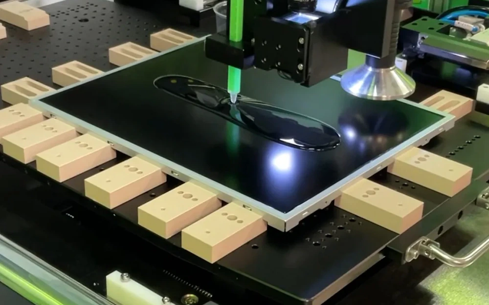
Gap or bondAir gap, spacer, gasket, tape, OCA, LOCA, perimeter bond, pressure, cure, rework, and contamination controlWhich optical and assembly method is actually included?
Mechanical supportBezel, bracket, carrier, ribs, fasteners, studs, datum surfaces, rear clearance, ventilation, and service directionHow is the display located and supported without stressing the module?
Electrical handoffDisplay FPC, cable, connector, board, pinout, power, data interface, backlight, touch link, retention, and test accessWhat powered and communication state exists at the customer connector?
AcceptanceDimensions, alignment, particles, bubbles, haze, scratches, powered pattern, communication, fit fixture, packaging, and traceabilityWhich checks prove the display assembly and which remain final-system validation?
Exploded display-integrated HMI stack showing front window, optical gap, display, bracket, and carrier
OPTICAL STACK

Choose Air Gap, Tape, Gasket, or Optical Bonding Deliberately

The best method depends on viewing, impact, contamination, rework, service, display construction, adhesive compatibility, cure process, cost, and the OEM validation plan. A concept rendering should never be treated as approval of an optical bonding process.

  • name every layer between the operator and the display image
  • separate clear aperture, viewing area, active area, and black-mask boundaries
  • define contamination and cosmetic inspection before selecting the assembly method
  • state whether rework or field service is required
Display HMI assembly in a fixture for alignment, powered image, connector, and cleanliness inspection
POWERED APPEARANCE

Inspect the Display Both Off and Powered

Dust, haze, reflections, bubbles, squeeze-out, mask alignment, backlight leakage, and pressure marks can appear differently when the display is active. The released sample should name the image, brightness state, viewing condition, and inspection distance used for approval.

  • use a controlled inspection image or test pattern
  • check active-area alignment from assembly datums
  • protect the window and display cable immediately after inspection
  • retain display lot and assembly revision with the approval evidence

Release the Assembly Through Five Controlled Decisions

01

Select the display boundary

Identify the exact display, controller or board boundary, front-window role, interface, lifecycle, and excluded software.

02

Close optical geometry

Align aperture, mask, viewing and active areas, orientation, gap or bond, bezel, gasket, and inspection zones.

03

Release support and interconnect

Define bracket, carrier, fasteners, FPC or cable, connector, retention, rear clearance, ventilation, and service direction.

04

Approve off and powered states

Inspect appearance, alignment, particles, bubbles, pressure, test image, backlight, communication, fit, and protection.

05

Control display and process changes

Lock sources, alternatives, optical materials, fixtures, cure or assembly records, packaging, notification, and requalification.

Diagnose Display HMI Problems by Optical, Mechanical, and Electrical Boundary

01

Image is clipped or shifted

Check display model, orientation, active and viewing areas, aperture, black mask, bracket, carrier, datum chain, coordinate transform, and revision.

02

Particles, haze, or bubbles appear

Review cleaning, environment, protective film, gap or bond material, cure, pressure, rework, inspection lighting, handling, and packaging.

03

Display is intermittent

Inspect cable bend, connector retention, pinout, power, interface level, backlight circuit, strain relief, rear clearance, and startup sequence.

04

Module passes but application fails

Separate display image or communication checks from customer software, graphics content, host timing, thermal design, EMC, machine logic, and safety validation.

Where Display-Integrated HMI Assemblies Fit

01

Industrial machine panels

Mounted displays combined with fixed controls, windows, brackets, connectors, and an equipment-facing handoff.

02

Medical instruments

Cleanable display modules with controlled optics, touch or keys, connectors, powered inspection, and customer software boundaries.

03

Laboratory equipment

Display fronts with dense controls, alignment, optical cleanliness, board interfaces, and revision-controlled integration.

04

Test and measurement

Serviceable screen modules coordinated with front-panel graphics, function keys, brackets, cables, and diagnostics.

05

Building controls

Wall or enclosure displays integrated with touch or keys, carrier, connector, mounting, and protected shipment.

06

Foodservice equipment

Operator displays combined with durable graphics, keys or touch, sealing, cable routing, and repeatable enclosure fit.

RFQ PACKAGE

Send the Display Part, Front Optics, Mounting, and Powered State

If the display has not been selected, send the target active area, interface, environment, depth, lifecycle, and service constraints so the supply boundary can be reviewed.

  • display manufacturer part, drawing, source, revision, approved alternatives, interface, controller boundary, and lifecycle notes
  • front outline, window material, print, black mask, clear aperture, viewing area, active area, orientation, and surface requirements
  • air gap, spacer, gasket, tape, optical adhesive, cure, cleanliness, rework, service, and cosmetic inspection expectations
  • bezel, bracket, carrier, fasteners, studs, datums, rear clearance, ventilation, shock support, and installation direction
  • FPC or cable, connector, pinout, power, backlight, communication interface, retention, diagnostics, and test access
  • sample quantity, annual estimate, powered test pattern, optical limits, fit fixture, packaging, traceability, and change control
Send Display HMI Files

Display-Integrated HMI Assemblies FAQ

How is this different from a panel with a display window?

A display-window panel controls the transparent aperture, print, mask, sensing, and surrounding geometry. This route includes a named display module or released display subassembly plus its mounting, interconnect, optical inspection, and customer handoff.

Is optical bonding included?

Only when the quotation names the display, front material, adhesive system, process, cleanliness, cure, inspection, rework, and validation scope. A display-integrated assembly may instead use an air gap, spacer, gasket, tape, or mechanical retention.

Can JASPER choose the display?

Display selection can be reviewed when the active area, interface, depth, environment, lifecycle, sourcing, optical state, software boundary, and approval method are available. The final selected part and alternatives must be released.

What powered testing can be included?

The project may define power-up, test pattern, backlight, communication, touch relationship, connector output, or customer-fixture checks. These do not automatically validate the final application software or machine.

How are display substitutions controlled?

Approved alternatives should be compared for mechanics, active and viewing areas, optics, connector, pinout, interface, timing, power, backlight, configuration, lifecycle, and required customer requalification.

Related HMI and Interface Routes

Make the display model, optical stack, cable, and powered approval state explicit.

JASPER can review the front window, named display, bracket or bond, interconnect, carrier, connector, mounting, optical cleanliness, powered inspection, packaging, and change control as one display-integrated HMI assembly.

Start Display HMI ReviewContact Engineering