Dongguan, Guangdong 523927, China[email protected]+86 136 3262 5290
Home / Products / HMI Assembly / Custom Capacitive Touch HMI Assemblies
ASSEMBLED TOUCH AND DISPLAY INTERFACES

Custom Capacitive Touch HMI Assemblies

A capacitive touch HMI assembly extends beyond the decorative cover and sensor. The released scope may include the touch front, named display, controller or interface PCB, lighting, rear carrier, internal FPC or cable, connectors, gasket, mounting hardware, configuration state, and assembly checks required before the OEM integrates the module.

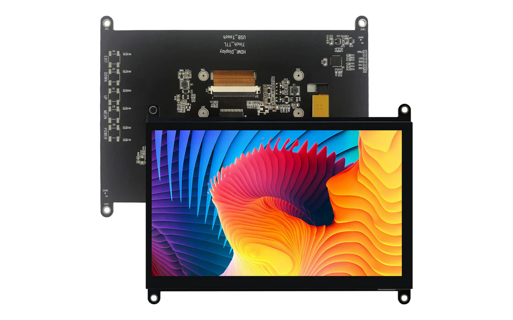
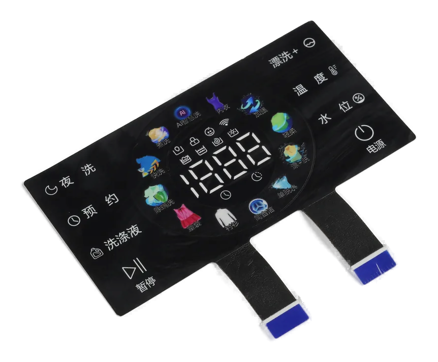
Custom capacitive touch HMI assembly with glass front, display, interface PCB, rear carrier, and connector
Beyond the touch frontdisplay, interface electronics, carrier, interconnect, connector, and mounting
Installed field reviewedcover, sensor, display, ground, bezel, gasket, rear metal, and cable state
Behavior boundary namedtouch detection, controller output, display state, host action, and system validation separated

This Route Owns the Assembled Module, Not Only the Sensing Front

The Capacitive HMI Front Panel product stops at the ready-to-integrate physical operator front. This route is appropriate when the supplied bill of material must extend through a named display, interface electronics, rear carrier, internal interconnect, connector, and broader assembly evidence.

Capacitive behavior changes after the display, grounding, bezel, mounting hardware, gasket, rear electronics, and enclosure are present. The assembly sample should reproduce those physical conditions before controller or host behavior is approved.

Touch detection, controller output, display response, application action, PLC logic, and machine behavior are different events. The quotation must state which events JASPER checks and which remain customer validation.

Custom Capacitive Touch HMI Assemblies fit when:

  • the capacitive sensor, display, electronics, carrier, and connector must arrive as one installed module
  • the OEM wants one owner for internal touch and display interconnects before the host connection
  • grounding, rear metal, mounting, gasket, and display conditions can be represented during sample approval
  • the customer retains or clearly assigns application software, machine behavior, safety logic, and final compliance

Six Controls Separate a Touch HMI Module from a Cosmetic Front

The critical decisions sit between the visible surface, the sensing field, the display electronics, and the customer host.

01

Touch and viewing geometry

Release control

Release active touch areas, display active and viewing areas, clear aperture, black mask, bezels, icons, edge keep-outs, and datums.

If it is missing

The screen looks aligned while the touch coordinates or fixed controls are shifted.

02

Installed sensing field

Release control

Define cover, adhesive, sensor, display, air gaps, optical layers, ground, shields, rear metal, gasket, and enclosure references.

If it is missing

The loose front works but misses or falsely triggers after the complete module is assembled.

03

Display and controller scope

Release control

Name the display, touch controller, interface PCB, firmware or configuration file, source, revision, and owner.

If it is missing

A component is shown in the concept but has no controlled supply, configuration, or lifecycle path.

04

Internal interconnect

Release control

Release FPCs, cables, board-to-board connectors, routing, bend limits, shielding, ground points, retention, and service access.

If it is missing

Touch or display output becomes intermittent after assembly, vibration, or customer installation.

05

Host handoff

Release control

Define power, connector, pinout, communication interface, startup state, diagnostics, ESD ground path, and excluded host logic.

If it is missing

Both parties can power the module but disagree about the state or data available at the connector.

06

Function evidence

Release control

Separate visual, touch, display, communication, fixture, software, machine, and regulatory checks with named acceptance records.

If it is missing

An assembly-level test is later interpreted as approval of the customer's application or finished equipment.

Release the Capacitive HMI by Physical Layer and Behavior Owner

The responsibility table should distinguish what is installed, what is configured, what is tested, and what the customer must validate in the final host.

BoundaryOptions to ReviewRelease Question
Operator frontGlass or polymer cover, print, touch sensor, fixed keys, sliders, coordinate area, windows, icons, and lightingWhich visible and sensing areas belong to the supplied front?
Display stackNamed display, clear aperture, active and viewing areas, air gap, gasket, optical adhesive, bracket, bezel, and cleanlinessIs the display supplied, and what installed optical state is approved?
Touch electronicsController included or excluded, interface PCB, configuration, firmware boundary, grounding, shielding, and tuning ownerWhat touch data or output state exists at customer handoff?
Internal wiringFPC, cables, connectors, bend zones, retention, ground straps, power, display interface, and test accessWhich internal connections arrive complete and serviceable?
Mechanical moduleRear carrier, frame, gasket, studs, fasteners, mounting datums, enclosure support, ventilation, and cable exitWhat physical state can the OEM mount without changing the sensing field?
AcceptanceAppearance, dimensions, touch map, display image, lighting, communication, fixture, configuration record, packaging, and traceabilityWhich evidence proves the module and which checks remain host or machine validation?
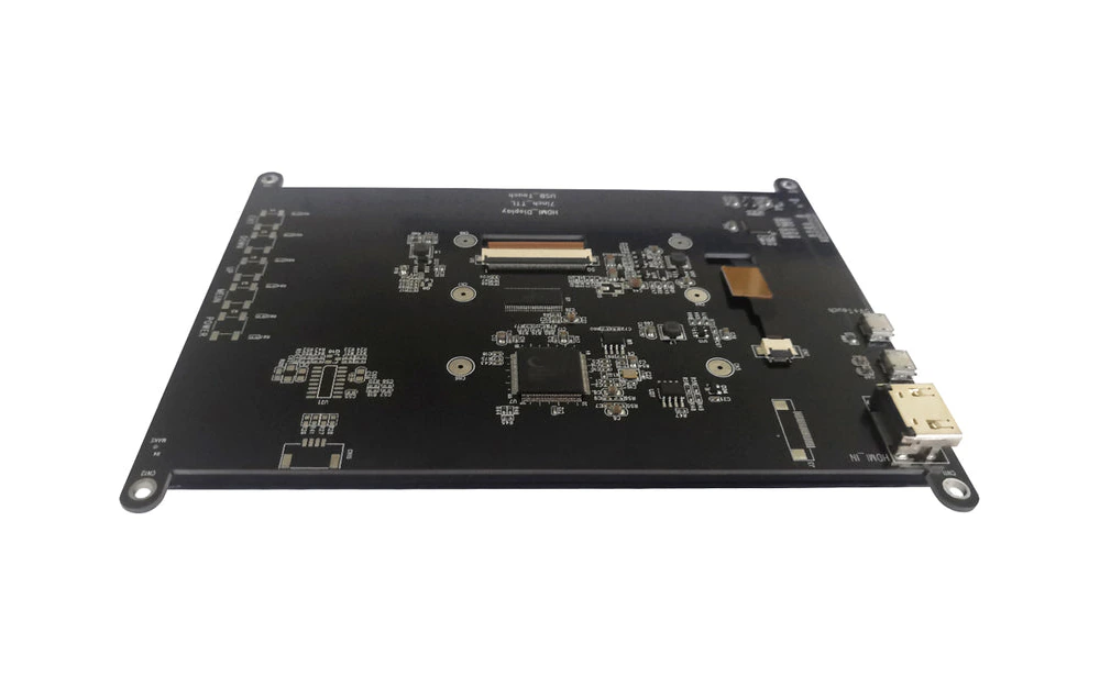
Capacitive touch HMI module with display, electronics, rear carrier, and customer connector
INSTALLED TOUCH FIELD

Approve Touch Behavior with the Display and Rear Structure Present

The display, bracket, ground path, gasket, bezel, cable shield, rear PCB, fasteners, and enclosure support all change the capacitive environment. A sensor sample approved on a bench is not sufficient evidence for an assembled HMI module.

  • validate fixed controls and coordinate touch in the production stack
  • include intended ground, bezel, gasket, rear metal, and display power states
  • exercise wake, disabled, cleaning, held touch, and disconnected conditions
  • record controller or configuration files with the approved hardware revision
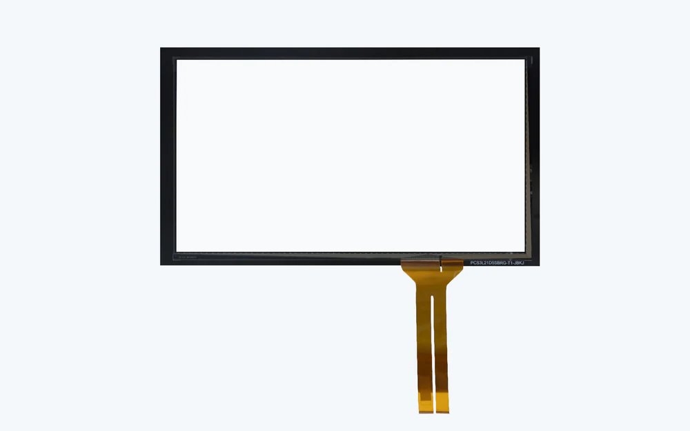
Exploded capacitive touch HMI assembly showing cover, sensor, display, interface PCB, and carrier
HOST RESPONSIBILITY

Name the Output at the Connector Before Discussing HMI Function

A module may deliver raw electrodes, controller channels, coordinates, key events, display power, a serial interface, or a higher-level message. Each handoff implies different firmware, diagnostics, host logic, and failure ownership.

  • define power rails, signal levels, interface, pinout, startup, and fault state
  • identify who owns touch tuning, display initialization, and configuration loading
  • separate module communication from application acceptance and machine action
  • retain an interface-control document with every approved revision

Release the Assembly Through Five Controlled Decisions

01

Define the user interaction

Map fixed inputs, coordinate touch, display content boundaries, feedback, disabled states, and required host outcomes.

02

Close the installed stack

Align cover, sensor, display, optical gap, ground, bezel, gasket, carrier, rear electronics, and mounting.

03

Release electronics and files

Name controller, interface PCB, display model, FPC or cable, connector, firmware boundary, configuration, and test access.

04

Approve the module state

Exercise touch, display, lighting, communication, fit, startup, fault, protection, and packaging in representative conditions.

05

Control hardware and configuration

Lock parts, sources, revisions, files, fixtures, records, substitutions, notification, and requalification triggers.

Locate Capacitive HMI Failures by Layer and Owner

01

Touch changes after integration

Review display power, rear metal, bezel, ground, gasket, fasteners, cable shield, enclosure support, controller file, and host filtering.

02

Display and touch are misregistered

Compare viewing area, active area, sensor datum, cover print, display bracket, carrier, assembly fixture, coordinate transform, and revision.

03

Communication is unstable

Check power, ground reference, internal FPC or cable, connector retention, interface level, shielding, startup order, and diagnostics.

04

Module passes but product fails

Separate module evidence from customer application, PLC or machine logic, field wiring, enclosure, complete EMC, safety, and regulatory validation.

Where Capacitive Touch HMI Assemblies Fit

01

Industrial operator terminals

Custom touch and display modules supplied to a defined equipment connector and enclosure interface.

02

Medical and laboratory devices

Cleanable touch HMIs with controlled display, disabled, cleaning, alarm, grounding, and customer software boundaries.

03

Building controls

Wall or equipment interfaces combining touch, display, lighting, rear electronics, carrier, and serviceable handoff.

04

Appliances

Integrated touch and display fronts with released sensing, optical, mounting, connector, and powered-state evidence.

05

Test and measurement

Display-linked coordinate input plus fixed functions, interface electronics, diagnostics, and revision-controlled integration.

06

Transportation controls

Mounted touch HMIs coordinated with gloves, moisture states, lighting, vibration support, grounding, and host electronics.

RFQ PACKAGE

Send the Touch, Display, Electronics, and Host Boundary Together

A useful quote starts with the installed module concept and the state expected at the customer connector, even when controller or display selection is still open.

  • front outline, graphics, touch map, display active and viewing areas, window, lighting, and operator states
  • cover, sensor, adhesive, optical stack, air gap, bezel, gasket, ground, shield, rear metal, and enclosure model
  • display model, touch controller, interface PCB, configuration, firmware boundary, sources, and lifecycle concerns
  • internal FPC, cables, connectors, pinout, power, communication interface, retention, and test access
  • carrier, brackets, fasteners, mounting datums, rear clearance, cooling or ventilation, and service direction
  • prototype quantity, annual estimate, touch and display checks, fixture, records, packaging, traceability, and change control
Send Touch HMI Files

Custom Capacitive Touch HMI Assemblies FAQ

How is this different from a capacitive HMI front panel?

The front-panel route owns the physical cover, print, sensor, circuit, connector, window, lighting, bonding, gasket, and carrier boundary. This route is for a broader module that may additionally include a supplied display, interface electronics, internal wiring, configuration, and assembly-level function checks.

Is the display included?

Only when its exact model, source, mounting, optical state, interface, configuration, inspection, lifecycle, and replacement rule appear in the released scope.

Does JASPER provide HMI software?

Application software, PLC logic, SCADA content, machine behavior, and safety functions are excluded unless separately defined. The assembly scope must name any supplied controller or configuration file.

Can touch tuning be included?

A controller configuration or tuning activity can be assigned when the installed stack, test states, host interface, acceptance method, file ownership, and retuning triggers are explicit.

What must the OEM validate?

The OEM should validate the module in the final enclosure with its power, host electronics, software, field wiring, operator conditions, machine behavior, EMC environment, safety logic, and regulatory plan.

Related HMI and Interface Routes

Approve the touch field, display, electronics, and host handoff in one installed module.

JASPER can review the capacitive front, display, interface electronics, internal wiring, carrier, connector, mounting, configuration state, inspection, and packaging as one custom touch HMI assembly.

Start Touch HMI ReviewContact Engineering