
For an OEM deciding between a graphic overlay vs membrane switch, the boundary is electrical function. Order a graphic overlay when the equipment already has switches or sensors and the purchased part only needs legends, windows, surface features, and attachment. Order a membrane-switch assembly when that part must close a circuit and deliver defined outputs through a tail or connector. Many membrane switches use a graphic overlay as their top layer, so the options are related rather than mutually exclusive. This article separates the drawings, tests, and replacement scope for each choice.
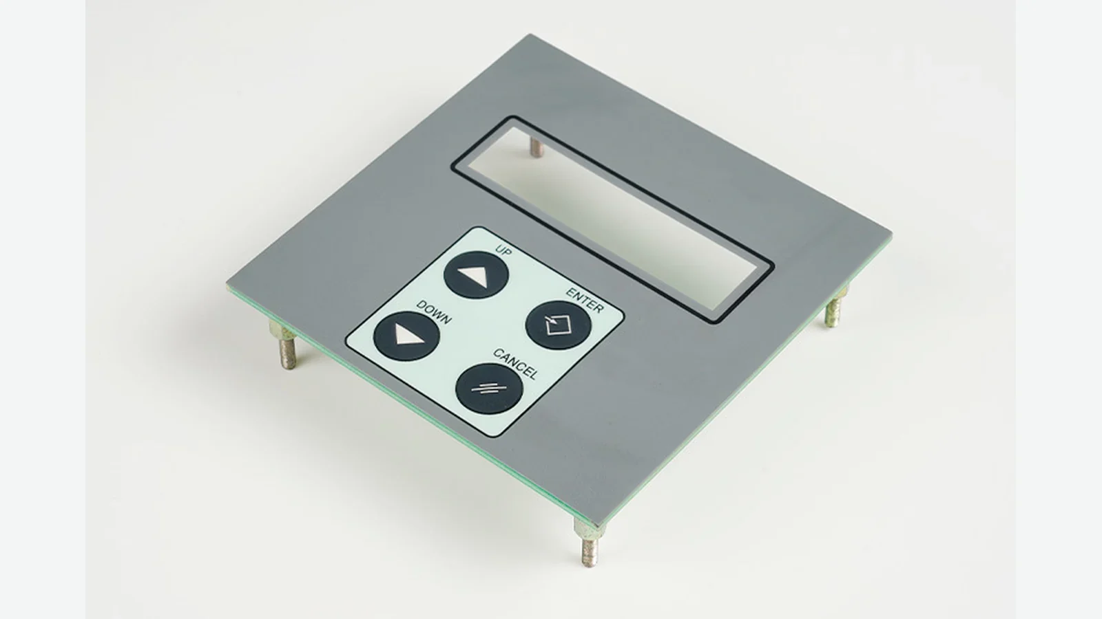
Quick Verdict: Choose by the Purchased Part’s Output
A graphic overlay is the right scope when the deliverable stops at the visible interface. A membrane switch is the right scope when the deliverable must produce an electrical state change. That first decision prevents a quotation for printed film from being mistaken for a quotation for a tested switch assembly.
| Decision dimension | Graphic overlay scope | Membrane switch scope |
|---|---|---|
| Primary output | Visual, protective, optical, or tactile guidance | Defined electrical contact or input signal |
| Existing controls behind the face | Mechanical switches, PCB buttons, sensors, or a display already provide input | The purchased assembly provides the switching contacts |
| Circuit and pinout | Outside the overlay part number | Inside the switch drawing and acceptance plan |
| Tail and connector | Not normally part of an overlay-only deliverable | Specified when the design uses them |
| Tactile element | Embossing may guide a finger but does not by itself create an electrical switch | Dome, formed contact, or another project-defined actuation construction may be included |
| Appearance tests | Required | Required for the top overlay and windows |
| Electrical tests | Not applicable to the overlay alone | Required to the limits on the approved switch drawing |
| Replacement unit | Overlay only, if the product was designed for that service operation | Complete switch or a controlled subassembly, depending on the architecture |
| Default answer | Use when switching already exists | Use when electrical switching belongs in the purchased interface |
The word overlay can still appear in both bills of material. The difference is whether the supplier is delivering only the face layer or a complete electrical assembly behind it.
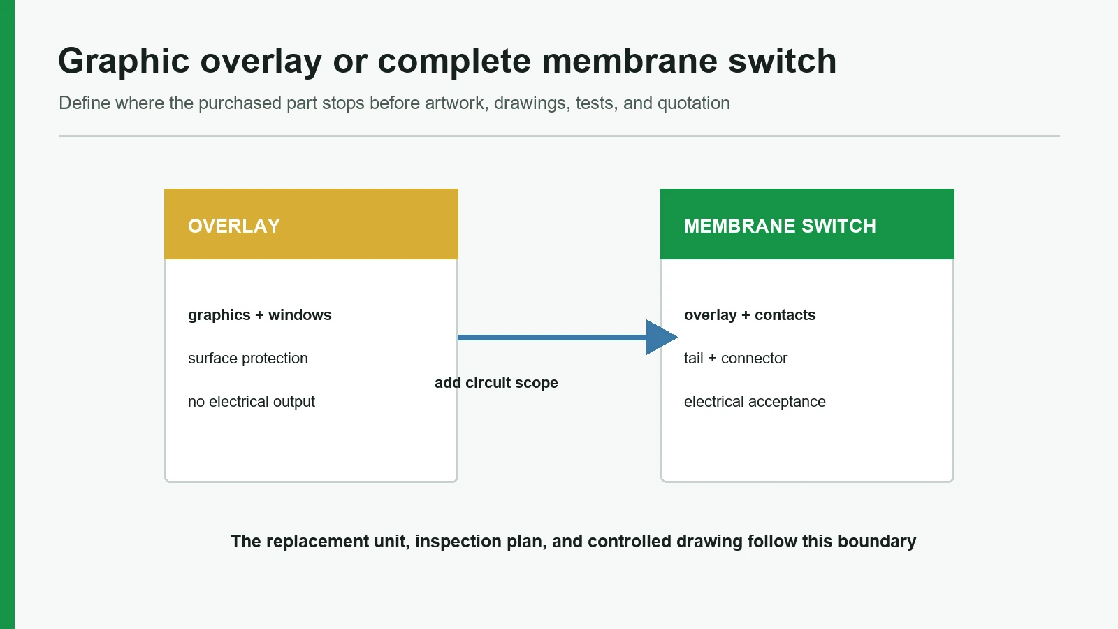
Graphic Overlay vs Membrane Switch: The Stack Boundary
The stack boundary is the most reliable definition. A graphic sheet remains separate from the conductors, pressure-sensitive adhesive, circuit sheet, spacer, and optional tactile parts in a membrane switch. These are representative functions rather than a mandatory layer count. (Molex membrane-switch literature; 3M membrane-switch stack brochure)
The graphic overlay function
A standalone overlay gives the operator a readable, cleanable, and dimensionally located front surface. It may carry subsurface-printed legends, transparent or tinted windows, selective textures, cutouts, and embossed key guides. It may also cover controls mounted in a housing. None of those features automatically adds conventional membrane-switch contacts.
STANDALONE GRAPHIC OVERLAY — representative boundary
Operator
front finish / hardcoat, if specified
clear film + second-surface graphics
selective adhesive / full adhesive
OEM enclosure, display, PCB button, mechanical switch, or sensor
Polyester and polycarbonate are both used for interface films. The useful question is not “Which polymer always wins?” It is which named grade, finish, primer, thickness, emboss geometry, ink system, and exposure plan fits the application. PET and PC interface films are available in gloss, antiglare, textured, clear, tinted, and application-specific grades and gauges. (MacDermid Alpha hardcoated interface films; Covestro film selector)
The membrane-switch assembly function
A membrane switch adds an electrically functional stack. Depending on the design, that stack can include an overlay, overlay adhesive, spacer, circuit substrate, printed conductors and dielectrics, contact features, tactile elements, tail, connector, rear adhesive, shield, backer, or lighting components. The approved drawing—not a generic layer count—defines what is present.
MEMBRANE SWITCH — representative boundary
Operator
graphic overlay
overlay adhesive / dome retainer, as designed
spacer and optional tactile element
contact and circuit layer(s) · tail · connector / termination
rear adhesive / shield / backer, as designed
OEM enclosure and controller
The circuit substrate is not merely an overlay printed with ordinary graphics. A functional layer can require heat-stabilized film plus project-specific silver, carbon, and dielectric ink systems; other circuit technologies may also be selected. Overlay-film selection and circuit-substrate selection are separate engineering decisions. (Autostat circuit film; printed electronic inks)
For a deeper view of the interfaces between those layers, see the membrane switch layer stack.
Where a Standalone Graphic Overlay Fits Better
The graphic overlay function is complete when the OEM already owns the switching architecture and needs a separate human-facing surface. The overlay wins on scope clarity in three common situations.
Existing controls already register the input
A housing may contain discrete mechanical switches, PCB-mounted tact switches, a silicone keypad, a capacitive sensor, or another input device. In that architecture, the overlay labels and protects the interface while the device behind it performs the electrical work. Adding a second switching circuit inside the overlay would duplicate function and complicate the bill of material.
Artwork can be revised independently
Language, model identification, warnings, colors, or key legends may change while the controls and electronics remain fixed. A separately controlled overlay drawing can isolate that revision—provided the enclosure and service plan allow the layer to be removed and replaced without damaging adjacent parts. “Overlay-only” does not automatically mean “field-replaceable.” Adhesive, edge sealing, alignment, and revalidation still matter.
The RFQ should exclude circuit risk
If the supplier is not being asked to own contact geometry, continuity, pinout, tail routing, connector compatibility, or actuation performance, an overlay-only RFQ keeps those obligations outside the part. The quotation can then focus on artwork, material grade, windows, finish, dimensions, adhesive pattern, application surface, and exposure conditions.
A standalone overlay is not the best choice when the purchased interface must itself close a circuit. Embossed keys can locate a touch area, but embossing alone does not create the missing electrical function.
Where a Membrane Switch Fits Better
A membrane switch fits when the OEM wants one controlled interface assembly to provide both the visible surface and defined electrical inputs. It earns the larger scope in three parallel situations.
The interface must deliver a tested electrical output
The switch drawing can define key contacts, circuit topology, pinout, tail exit, termination, and electrical acceptance. Those requirements move the deliverable beyond a control-panel overlay. The controller still belongs to the OEM system, but the switch supplier owns the agreed input assembly boundary.
Tactile, optical, and electrical geometry must align
Key legends, emboss features, optional domes, contacts, LED windows, and the enclosure cannot be reviewed as unrelated coordinates. A membrane-switch drawing controls their registration in one stack. A tactile element is optional and design-specific; it is not evidence that every membrane switch has the same feel or actuation force.
One part number should include the tail and connector interface
When the tail direction, length, conductor mapping, pitch, stiffener, bend route, and connector termination must arrive as part of the HMI, the complete membrane-switch scope is easier to audit than separate overlay and circuit purchases. That convenience also expands the validation burden: cosmetic approval alone is no longer enough.
A membrane switch is not automatically the best choice when switching already exists, when operators need long-travel individually replaceable controls, or when the application calls for another sensing or load-switching architecture. “Integrated” is useful only when the integration matches the system requirement.
Drawing Package: Control Panel Overlay vs Switch
The drawing package should state the purchased boundary before dimensions are reviewed. Graphic overlay printing needs controlled artwork and material/exposure inputs. A complete switch needs those same inputs plus an electrical definition.
| Drawing or controlled input | Overlay only | Membrane switch | Owner before supplier review |
|---|---|---|---|
| Part outline, cutouts, datums, and critical dimensions | Required | Required | OEM mechanical/design team |
| Vector artwork with separate color, window, texture, emboss, die, and adhesive layers | Required | Required | OEM industrial/graphic design |
| Color reference and measurement condition | Required when color is controlled | Required when color is controlled | OEM quality/design |
| Named film grade, finish, thickness, and print surface | Required or explicitly supplier-proposed | Required or explicitly supplier-proposed | Joint material review |
| Housing material, coating, texture, curvature, and application surface | Required | Required | OEM mechanical/manufacturing |
| Adhesive coverage, keep-outs, gasket land, and edge boundary | Required | Required | Joint mechanical review |
| Window type, optical target, display gap, and LED locations | As applicable | As applicable | OEM optical/electrical team |
| Key map and active switch zones | Reference only if controls sit behind overlay | Required | OEM electrical/HMI team |
| Circuit schematic or matrix, normally open/closed state, and pinout | Not in overlay scope | Required | OEM electrical team |
| Project voltage, current, contact, and interface acceptance limits | Not in overlay scope | Required | OEM electrical/safety team |
| Tail exit, length, route, bend controls, pitch, stiffener, and termination | Not in overlay scope | Required when present | Joint electrical/mechanical review |
| Tactile construction and project-specific force/feel target | Emboss guidance only | Required when tactile response is controlled | OEM ergonomics/quality |
| Shield, ground path, lighting circuit, and test points | Not in overlay scope | Required when present | OEM electrical/EMC team |
Color callouts such as Pantone or RAL references are useful identifiers, but a measurable acceptance rule needs more. ISO 13655:2017 covers spectral measurement and colorimetric computation for graphic-arts images; ASTM D2244-25 covers color-difference calculations. Neither document chooses the OEM’s reference sample, measurement condition, formula, or tolerance. Put those decisions on the drawing or inspection plan. (ISO 13655:2017; ASTM D2244)
Material selection should be handled the same way. The membrane switch materials review can compare candidate grades, but the released drawing should identify the approved construction or the controlled substitution process.
Validation Matrix: Test the Failure Mechanism, Not the Product Name
Graphic overlays and membrane switches share appearance, dimension, window, surface, and attachment checks. A switch adds electrical and actuation checks. Environmental or ingress validation may involve either component, but the test article and installation state must match the claim being made.
| Validation target | Overlay-only scope | Added membrane-switch scope | Method boundary |
|---|---|---|---|
| Artwork and color | Legend, color, opacity, registration, approved master | Same top-layer checks | ISO 13655 / ASTM D2244 can support measurement; project sets condition and tolerance |
| Dimensions and fit | Outline, holes, windows, emboss, adhesive pattern, housing fit | Same plus alignment to contacts, domes, tail, connector, and enclosure | Use released drawing, datum scheme, gauge plan, and agreed sampling |
| Gloss and transparent windows | Surface gloss, haze, luminous transmittance where specified | Same plus alignment and performance with the installed display or light source | ASTM D2457 and D1003 are candidate material methods, not complete display-readability tests |
| Surface abrasion | Defined face or window, abrader, load, cycles, evaluation | Same on the complete top surface | ASTM D1044 applies to transparent plastics under its stated conditions; it does not predict finger or wipe life |
| Chemical exposure | Named chemical, concentration, contact mode, time, temperature, rinse, recovery, visual/adhesion criteria | Same plus post-exposure electrical and actuation checks when relevant | ASTM D1308 covers household chemicals; other fluids need a custom matrix |
| Adhesive bond | Actual film/adhesive/housing surface, preparation, pressure, dwell, peel direction/rate | Same plus spacer and interlayer bonds where controlled | ASTM D3330 can compare PSA peel under defined conditions; peel is not proof of sealing or field life |
| Open/short/continuity | Not applicable to a passive overlay | Check every required input/output state and unwanted connection to drawing limits | Electrical limits and equipment belong in the approved test plan |
| Actuation and return | Not an electrical overlay test | Check the actual key construction, fixture, load profile, rate, environment, and acceptance values | Do not borrow a generic force or travel number from another stack |
| Contact cycling | Not applicable | Cycle the actual assembly and measure agreed changes before, during, or after exposure | ASTM F1578-24 is the active membrane-switch contact-closure cycling method; it supplies no universal life rating |
| Temperature / humidity / salt exposure | Apply when the installed use warrants it; reassess appearance and bond | Add electrical and actuation checks | IEC 60068-2-14, IEC 60068-2-78, or IEC 60068-2-52 may frame a plan; the project selects severity and pass/fail |
| Installed ingress | Validate the completed panel-to-enclosure interface | Validate switch, perimeter, tail exit, connector, gasket land, and enclosure together | IEC 60529 classifies enclosures, not loose film or adhesive |
| Marking or switch certification | Evaluate permanent marking scope when required | Evaluate switch scope under the applicable program | UL says marking systems and adhesive-attached membrane switches are separate categories |
The standards in this table are candidates, not a universal checklist. Current ASTM F1578-24 describes cycling a membrane switch for a predetermined number of depress/release cycles and optionally under specified voltage and current; it does not publish a default “million-cycle” entitlement. (ASTM F1578-24)
Adhesive data require the same restraint. Graphic-attachment performance depends on surface preparation, substrate, dwell, temperature, and test method; published technical values are not automatic production limits. Select the adhesive against the real housing, texture, contamination controls, and assembly process; the membrane switch adhesive selection cannot be reduced to a tape number. (3M 467MP TDS)
An IP claim has an even stricter boundary. IEC 60529 applies its IP Code to enclosures for electrical equipment. A film, overlay, spacer, adhesive, or uninstalled switch cannot donate an IP65 or IP67 rating to the finished unit. Test the installed interface, including its perimeter, tail exit, connector, gasket land, fasteners, and enclosure geometry. (IEC 60529)
UL scope also changes with the product boundary. UL 969 addresses marking permanence, while adhesive-attached membrane switches controlling equipment use the separate WHSM2 category. A recognized film or label construction is not evidence that a proposed complete switch or finished machine is certified. (UL Solutions FAQ)
Failure Chain and Replacement Scope
Replacement begins with fault isolation. A front-surface symptom may still originate in the adhesive, display, switch stack, controller, enclosure, cleaning process, or installation. The table below defines the first boundary to inspect; it does not promise that any laminated product can be separated safely in the field.
| Observable symptom | Isolate first | Overlay-only action may fit when… | Full switch/system action may fit when… |
|---|---|---|---|
| Wrong legend, language, or approved color | Artwork revision, print master, lighting condition | The defect is confined to the controlled graphic layer and the architecture permits replacement | Electrical key mapping also changed, or the overlay cannot be separated without invalidating the assembly |
| Scratched, cloudy, or distorted window | Front film, hardcoat, cleaning agent, optical gap, display | The optical defect is confined to a replaceable overlay | Damage extends into lighting, display, spacer, adhesive, or sealed assembly |
| Edge lift or bubbles | Housing surface, cleaning, application pressure, adhesive pattern, trapped air | The overlay/housing bond is the only failed interface | Internal switch bonds or the enclosure sealing path are involved |
| Legend looks correct but a key gives no input | Controller, connector, tail, continuity, contact zone | An overlay action does not fit unless misalignment physically prevents intended actuation | Circuit, contact, spacer, dome, tail, connector, or controller requires repair or replacement |
| Key feel changes or becomes inconsistent | Overlay geometry, dome, spacer, support surface, contamination | A replaceable overlay is proven to be the sole mechanical cause | Tactile element, spacer, circuit stack, support, or complete assembly is implicated |
| LED icon is dim, uneven, or missing | Overlay opacity/window, light source, circuit, alignment, power | Film printing or window construction alone causes the optical defect | LED, light guide, circuit, connector, controller, or stack alignment is involved |
| Moisture appears inside equipment | Entire installed interface and enclosure | Testing proves a serviceable overlay bond is the only leak path | Tail exit, connector, gasket, housing, fastener, switch edge, or another enclosure path fails |
The practical rule is simple: an overlay replacement cannot repair an electrical open, unwanted short, damaged contact, failed dome, broken tail, connector fault, or controller problem. It may correct artwork, surface, window, or bond defects only when the product was designed for that replacement and the repaired interface is revalidated.
Decision Matrix: Which Construction Should the OEM Pick?
For graphic overlay vs membrane switch selection, choose the smallest scope that owns the required function and its verification. Do not pay for a circuit the system does not need, and do not omit a circuit that the purchased interface is expected to deliver.
| Project condition | Pick | Why |
|---|---|---|
| Mechanical switches or PCB buttons already generate the input | Graphic overlay | The face layer only needs graphics, windows, key guidance, and attachment |
| A separate capacitive or touch sensor already owns input detection | Graphic overlay or sensor-specific cover stack | Conventional membrane contacts would duplicate the sensing architecture |
| The purchased HMI must close defined contacts | Membrane switch | Electrical contacts and acceptance belong inside the part boundary |
| Tail, pinout, and connector must ship under the interface part number | Membrane switch | Those are electrical assembly requirements, not overlay artwork |
| Artwork may change while qualified electronics remain fixed | Separately controlled overlay, if service architecture permits | Revision scope can remain at the visible layer |
| Tactile key geometry must align with contacts and circuit | Membrane switch | Mechanical and electrical coordinates need one controlled stack |
| Long travel or individually field-replaceable buttons are required | Neither by default; assess rated mechanical controls | A thin laminated switch may not meet the service or feel requirement |
| A continuous display/touch UI is required | Neither by default; assess the relevant touch technology | A contact-based membrane-switch matrix solves a different input problem |
| The interface must switch a load outside the proposed membrane circuit’s verified rating | Neither by default; use an appropriately rated switching architecture | A graphic layer or unverified printed circuit is not a load-rating substitute |
Both options can be wrong if the product architecture is unclear. Freeze the sensing or switching method first, then define the face layer, circuit boundary, enclosure interface, and validation plan.
Project Inputs and Sample Approval
A supplier cannot choose the correct interface construction from a logo file and overall dimensions. The first review package should contain:
- the enclosure section, mounting surface, datums, cutouts, curvature, and available stack depth;
- vector artwork with separate graphic, window, texture, emboss, adhesive, and die layers;
- named color references plus the measurement or visual-master conditions;
- actual cleaning agents, contact method, concentration, temperature, frequency, and recovery expectations;
- indoor, outdoor, UV, humidity, salt, abrasion, glove, impact, and contamination conditions that genuinely apply;
- display and LED locations, window targets, viewing geometry, and backlighting requirements;
- for a switch, the circuit, pinout, electrical limits, tail/connector, tactile target, controller interface, and test conditions;
- prototype quantity, production revision controls, inspection plan, packaging needs, and acceptance authority.
Approve the first article against the same boundary:
| Approval group | Overlay-only sample | Membrane-switch sample |
|---|---|---|
| Visual | Artwork, color, finish, opacity, windows, defects | Same top-layer review |
| Mechanical | Outline, cutouts, emboss, fit, bond, edge condition | Same plus stack height, support, tail route, connector fit, key alignment |
| Optical | Window appearance and installed display/LED result | Same plus integrated lighting/circuit result when included |
| Electrical | Not applicable to the passive part | Pinout, open/short/continuity, contact behavior, indicators, shielding as specified |
| Environmental | Defined material/bond checks and installed-panel tests | Same plus post-exposure electrical and actuation checks |
| Release data | Approved artwork, material construction, drawing revision, inspection record | Same plus circuit revision, test program, tail/connector definition, electrical results |
The next step is to label the request OVERLAY ONLY or COMPLETE MEMBRANE-SWITCH ASSEMBLY before tooling or sample release. If the boundary is still uncertain, send the housing drawing and interface schematic for engineering review. JASPER’s first-party product pages present both constructions; alternatives should be evaluated against the same drawing, source, and acceptance requirements.
Frequently Asked Questions
What is the main difference between a graphic overlay and a membrane switch?
A graphic overlay is the user-facing printed and protective layer; a membrane switch is an electrical input assembly that commonly uses an overlay on top. If the purchased part must only label or cover controls, specify an overlay. If it must close contacts and provide a pinout, specify a membrane switch.
Is a graphic overlay part of a membrane switch?
Yes, in many conventional constructions the graphic overlay is the top layer of a membrane switch. The exact stack varies, so the released drawing must state whether it also includes adhesive, spacer, contacts, circuit layers, tactile elements, tail, connector, shield, lighting, rear adhesive, or a backer.
Does a membrane switch graphic overlay contain the circuit?
Not by definition. The membrane switch graphic overlay carries the visible interface, while the electrically functional conductors and contacts belong to circuit-related layers behind it in a conventional stack. Avoid treating an ordinary graphic print layer as a circuit unless the approved construction explicitly combines functions and defines the electrical tests.
Can a control panel overlay replace a membrane switch?
Only when another device already performs the switching or sensing. A control panel overlay can label mechanical switches, PCB buttons, displays, or sensor zones, but it cannot replace required contacts, a circuit, a tail, or a connector. Confirm the electrical block diagram before changing the part specification.
Can only the graphic overlay be replaced on a membrane switch?
Sometimes, but only when the product architecture was designed for that service operation. Replacement must not damage the circuit stack, shift key alignment, or invalidate the enclosure bond. If the fault is electrical or internal, replacing the top film alone will not correct it; the controlled repair may require the complete assembly.
What files are needed for an overlay versus a membrane switch?
Both need controlled mechanical dimensions, layered vector artwork, window and emboss data, material/finish, adhesive pattern, housing surface, and exposure conditions. A membrane switch also needs the circuit or matrix, key map, electrical limits, pinout, tail and connector definition, tactile target, optional lighting or shielding, and electrical acceptance plan.
How should an OEM compare graphic overlay vs membrane switch IP claims?
Ask what complete enclosure was tested, in what installed configuration, and to which IEC 60529 classification and procedure. A loose overlay, film, adhesive, or uninstalled switch does not inherit an equipment IP rating. The perimeter, gasket land, tail exit, connector, fasteners, and housing geometry must be included in the claimed boundary.
When is a membrane switch not the best interface?
A membrane switch may be the wrong fit when controls need long travel, individual field replacement, a different tactile mechanism, continuous touch sensing, or load switching beyond the verified circuit design. It may also be unnecessary when existing electronics already detect input and only a printed face layer is missing.
Technical References
- Source: Covestro Makrofol and Bayfol Film Selector Guide. Accessed 2026.
- Source: 3M membrane switch spacer and graphic attachment technical data. Accessed 2026.
- Source: ASTM F1578-24 membrane switch contact closure cycling. Accessed 2026.
- Source: ISO 13655:2017 graphic arts spectral measurement. Accessed 2026.
- Source: ASTM D2244-25 color difference calculation. Accessed 2026.
- Source: IEC 60529 enclosure protection classification. Accessed 2026.
- Source: Molex membrane-switch literature. Accessed 2026.
- Source: 3M membrane-switch stack brochure. Accessed 2026.
- Source: MacDermid Alpha hardcoated interface films. Accessed 2026.
- Source: Covestro film selector. Accessed 2026.
- Source: Covestro Makrofol/Bayfol selector. Accessed 2026.
- Source: 3M 468MP TDS. Accessed 2026.
- Source: 3M 7956MP TDS. Accessed 2026.
- Source: Autostat circuit film. Accessed 2026.
- Source: printed electronic inks. Accessed 2026.
- Source: ISO 13655:2017. Accessed 2026.
- Source: ASTM D2244. Accessed 2026.
- Source: ASTM F1578-24. Accessed 2026.
- Source: 3M 467MP TDS. Accessed 2026.
- Source: IEC 60529. Accessed 2026.
- Source: UL Solutions FAQ. Accessed 2026.
Define the purchased part boundary before RFQ
Send the artwork, housing, existing controls, required electrical output, windows, surface exposure, adhesive land, and replacement scope.