
Sensing map
ControlRelease the coordinate area, excluded zones, gesture intent, orientation, origin, and host coordinate transformation.
Failure modeNominal sensor coordinates do not align with the displayed controls after integration.
A custom PCAP touch panel places a transparent projected-capacitive sensor over a display active area to report coordinates and approved multi-touch gestures. This OEM route is engineered around the product display, controller, enclosure, and validation plan; it is not a phone digitizer, repair part, or standard consumer-screen replacement.
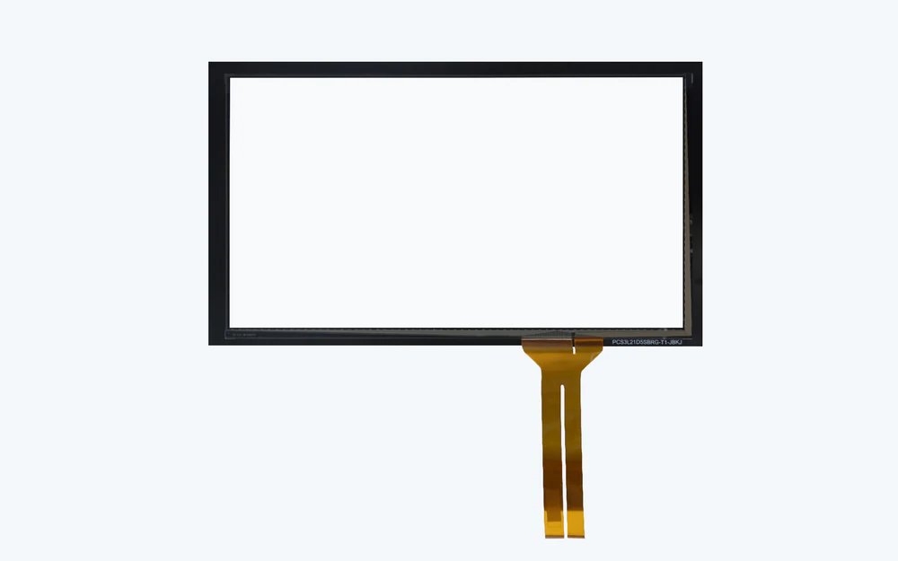
Projected-capacitive sensing uses patterned transparent electrodes and a controller to determine touch coordinates across a released area above a display.
The finished result depends on cover construction, sensor pattern, display position, grounding, controller configuration, flex routing, bezel geometry, edge tuning, and the electrical noise present in the installed product.
Use this page for custom OEM coordinate and multi-touch sensing over a display. Requests for replacement phone digitizers, repair screens, or catalog consumer panels are outside this manufacturing scope.
A clear panel can look correct while its coordinate map, edge response, or noise behavior remains unresolved.
Release the coordinate area, excluded zones, gesture intent, orientation, origin, and host coordinate transformation.
Failure modeNominal sensor coordinates do not align with the displayed controls after integration.
Define cover, printing, sensor construction, adhesive interfaces, surface treatment, and visible acceptance.
Failure modeHaze, pattern visibility, contamination, or interface defects appear over live content.
Place display active area, display view area, sensor active area, clear aperture, black mask, and bezel from common datums.
Failure modeThe image is clipped or touch registration drifts toward one edge.
Name the controller, tuning owner, firmware deliverable, communication interface, reset behavior, and approved configuration.
Failure modeSamples pass on a bench board but behave differently in the production host.
Review display mode, power architecture, grounding, shielding, charger states, nearby switching circuits, and controller diagnostics.
Failure modeFalse or missed touches appear only when the display or another subsystem changes state.
Control flex exit, connector, bend zone, strain relief, guard treatment, bezel gap, edge tuning, and nearby conductive parts.
Failure modeEdge touches become unstable or the interconnect shifts during final assembly.
The specification should connect every transparent layer and electrical interface to the installed display state used for approval.
| Decision | Options to Review | Release Question |
|---|---|---|
| Coordinate behavior | Single contact, project-defined multi-touch, gesture inputs, exclusions, orientation, and host mapping | Which coordinates and interactions must the host receive in each approved operating state? |
| Visible geometry | Display active area, view area, clear aperture, mask boundary, sensor area, bezel, and logo zones | Which datum controls registration between displayed content and sensed position? |
| Sensor construction | Cover material, printed border, transparent electrode stack, adhesive interfaces, tail, and surface treatment | Which construction and visible defects are approved on powered samples? |
| Electronics boundary | Controller supplied, customer controller, reference board, firmware ownership, interface, and diagnostics | Who releases tuning and how is the production configuration identified? |
| Display and enclosure | Named display, power modes, conductive frame, grounding, bezel, nearby metal, adhesive, and assembly sequence | Which installed conditions can change coupling, noise, or edge response? |
| Validation evidence | Coordinate map, edge checks, gesture set, noise states, environmental conditions, assembly samples, and retained references | What system evidence authorizes production and later changes? |
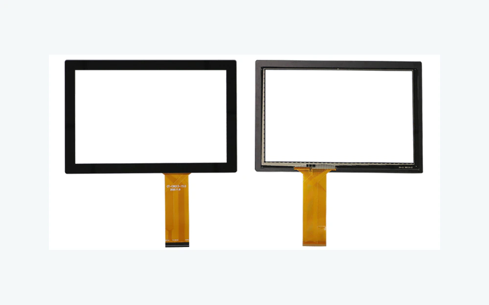
The display active area, visible aperture, sensor coordinate area, black mask, enclosure opening, and host graphics must share a controlled origin. Nominal center alignment does not expose accumulated movement at the edges.
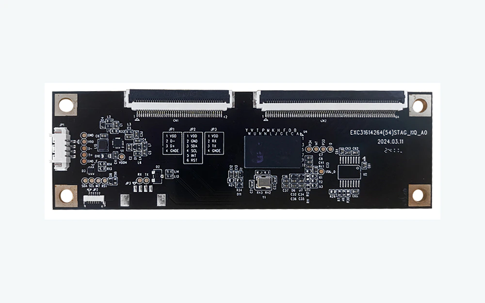
Display scanning, power conversion, grounding, cables, metalwork, chargers, and nearby emitters can change the signal seen by the controller. A reference-board demonstration is only one state, not the system release.
Document displayed controls, coordinate area, gesture intent, exclusions, operator conditions, and failure consequence.
Register display, view area, sensor, cover printing, flex, bezel, adhesive, and enclosure datums.
Confirm controller, firmware owner, host interface, grounding, display states, diagnostics, and change responsibility.
Check powered appearance, coordinate mapping, edges, gestures, noise states, flex routing, and enclosure interaction.
Lock stack, sensor pattern, controller configuration, display reference, assembly process, inspection, and revalidation triggers.
Check host mapping, orientation, display registration, sensor placement, cover datum, scaling, and approved firmware.
Review bezel proximity, edge tuning, cover print, conductive hardware, grounding, sensor pattern, and finger access.
Compare display states, power conversion, charger condition, grounding, shielding, moisture, firmware, and nearby circuits.
Inspect flex bend, connector seating, strain relief, controller supply, reset sequence, interface timing, and assembly handling.
Coordinate interfaces integrated with a named display, enclosure, controller, and equipment validation plan.
Smooth display controls whose visible area, cleaning state, grounding, and host mapping are reviewed together.
Embedded operator displays with controlled bezels, flex routing, power states, and system-owned validation.
Custom display interfaces requiring project graphics, coordinate mapping, and enclosure integration.
Integrated display controls where the sensor stack and electronics are released for the appliance design.
Low-volume or custom-format OEM interfaces that cannot use a standard consumer replacement panel.
A PCAP review becomes useful when the visible geometry and the powered system conditions arrive together.
It is a projected-capacitive sensor system that reports touch coordinates across a released area over a display through a controller and approved configuration.
No. JASPER reviews custom OEM PCAP panels around a product display, enclosure, flex, controller, and validation plan rather than supplying consumer repair screens.
Only when the project scope says so. The quotation and drawing should identify the controller source, tuning owner, firmware deliverable, host interface, and production configuration.
Yes for system approval. Display scanning, power modes, frame construction, grounding, cables, and enclosure hardware can change sensing behavior.
Approve powered appearance, active and view-area registration, coordinate mapping, edge behavior, required gestures, flex routing, controller configuration, and relevant system noise states.
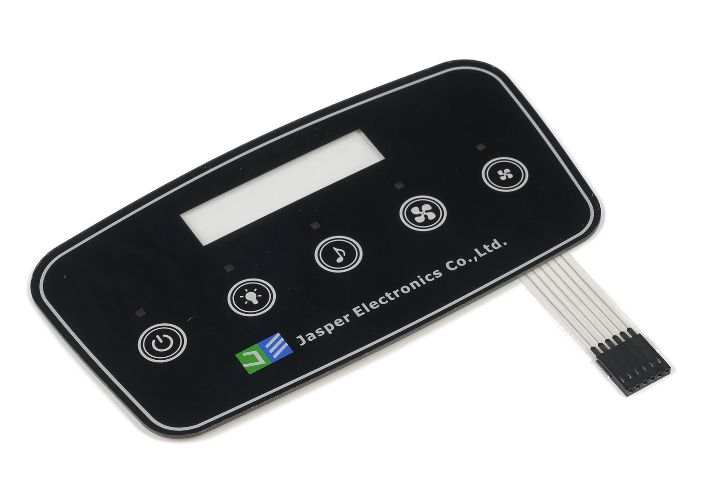
Compare fixed-key, display-window, backlit, PCAP, and front-panel routes.
Review Resource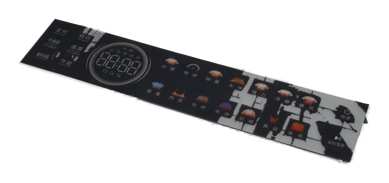
Use a transparent viewing area with fixed capacitive controls around the display.
Review Resource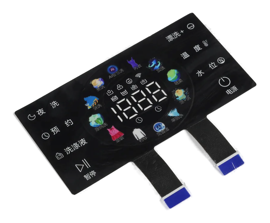
Extend PCAP responsibility into a ready-to-integrate physical front subassembly.
Review ResourceJASPER can review the PCAP stack, coordinate map, active and view areas, flex, controller boundary, display noise, enclosure edge, and installed validation plan as one OEM interface.
Share the project basics. JASPER will review the stack, materials, connector, quantity, and production risks.