Dongguan, Guangdong 523927, China[email protected]+86 136 3262 5290
Home / Products / Custom Capacitive Touch Panels for Sealed OEM Interfaces
CUSTOM CAPACITIVE INTERFACE ENGINEERING

Custom Capacitive Touch Panels for Sealed OEM Interfaces

Custom capacitive touch panels combine a sealed decorative surface with project-specific sensing, graphics, feedback, controller behavior, and enclosure integration. Choose the route by the kind of input the operator needs and the boundary your team wants JASPER to supply.

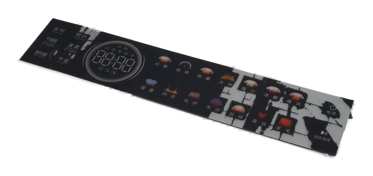
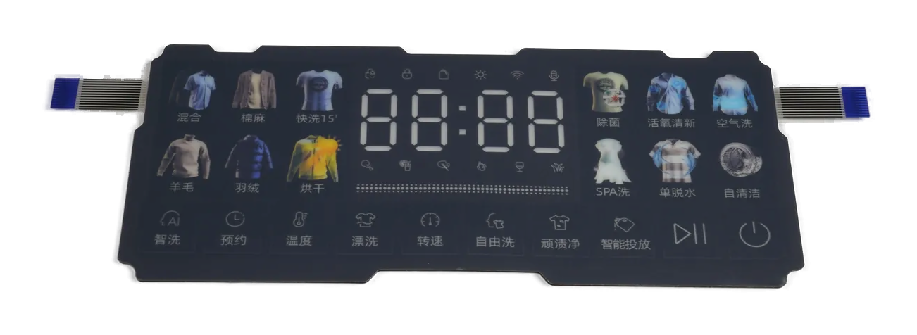
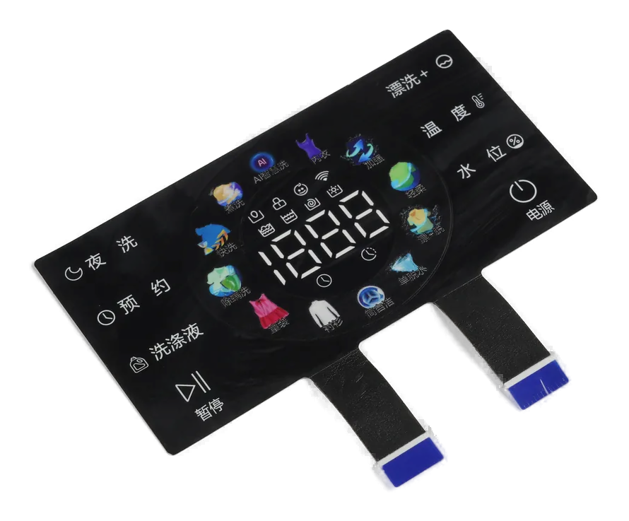
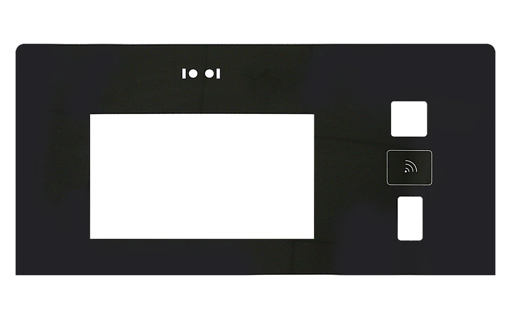
Custom capacitive touch panels arranged as sealed OEM control interfaces
6 product routesdiscrete switches, keypads, PCAP, windows, backlighting, and HMI fronts
One installed fieldcover, electrodes, routing, nearby metal, controller, and enclosure
State-led approvalbare hand, glove, moisture, cleaning, disabled, wake, and fault behavior

Capacitive Touch Panel Products

Choose the product route by the physical interface, input model, display boundary, lighting, and assembly responsibility that still need to be released.

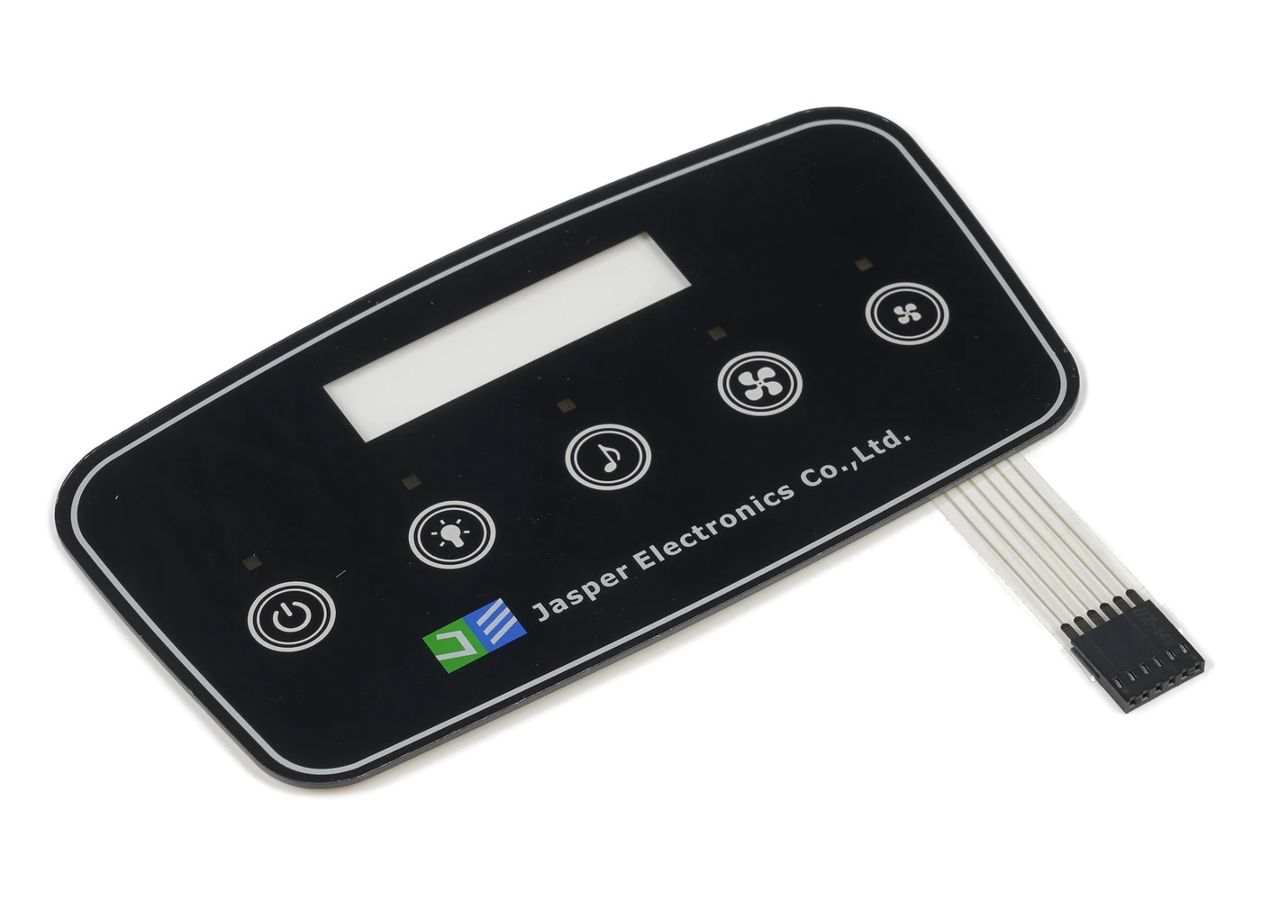
Capacitive Touch Switches

Capacitive Touch Switches

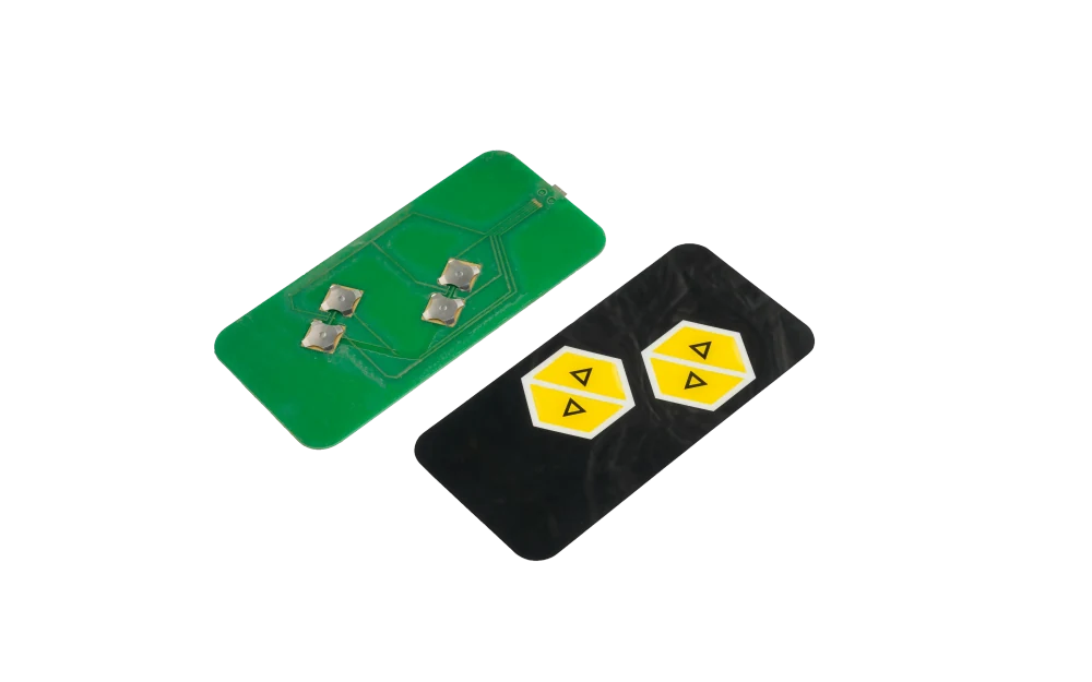
Discrete no-travel touch zones with controlled electrodes, spacing, routing, feedback, and host states.

Choose it when: Choose this route when each marked area represents a separate command rather than a coordinate surface.

View Capacitive Touch Switches
Capacitive Touch Keypads

Capacitive Touch Keypads

Multi-key arrays with a released channel map, neighboring-key rules, sliders or wheels, lighting, and feedback.

Choose it when: Choose this route when several discrete inputs must be organized and interpreted as one keypad.

View Capacitive Touch Keypads
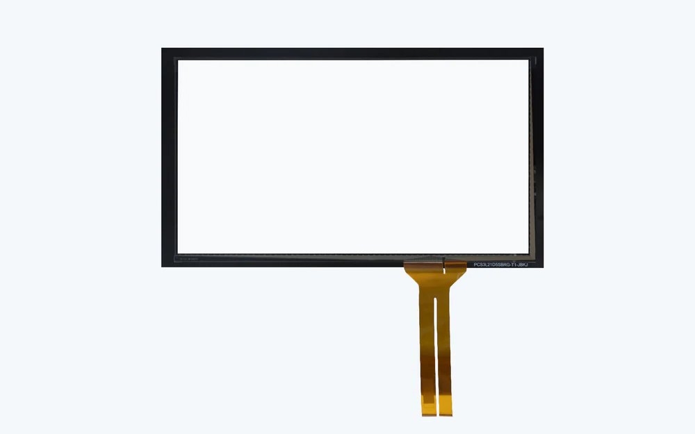
PCAP Touch Panels

PCAP Touch Panels

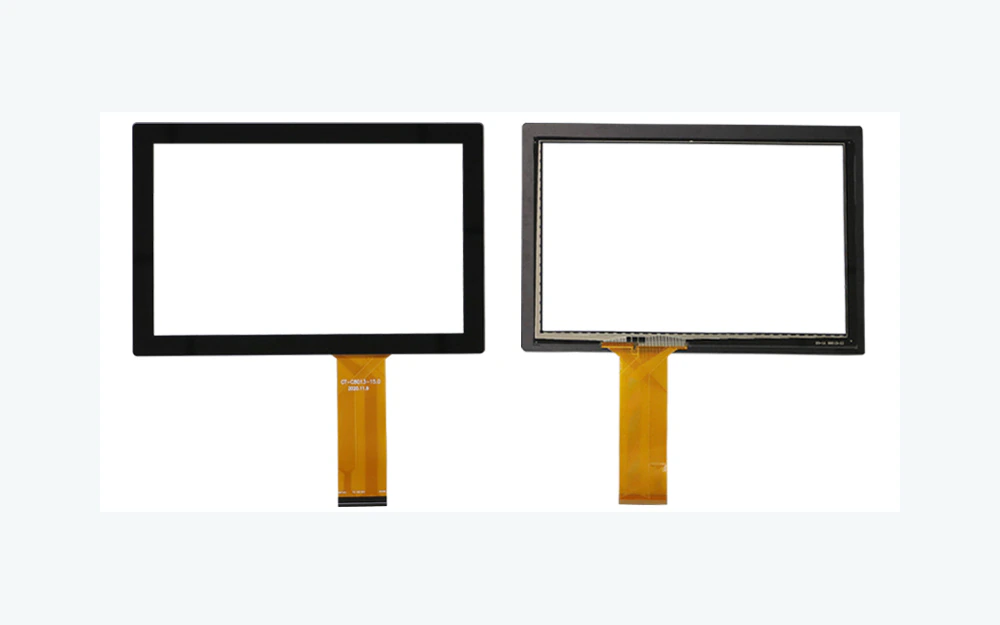
Projected-capacitive coordinate sensing for displays, gestures, and application-defined touch tracking.

Choose it when: Choose this route when the interface must resolve positions across an active surface instead of fixed commands.

View PCAP Touch Panels
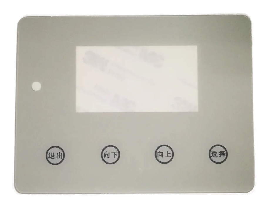
Touch Panels with Display Windows

Touch Panels with Display Windows

Printed capacitive fronts aligned to displays, indicator windows, dead-front areas, and enclosure openings.

Choose it when: Choose this route when optical registration and the sensing field must share one front panel.

View Touch Panels with Display Windows
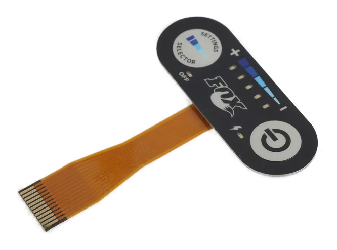
Backlit Capacitive Panels

Backlit Capacitive Panels

Capacitive controls coordinated with illuminated icons, light blocking, diffusion, and powered-state graphics.

Choose it when: Choose this route when the operator depends on controlled visual feedback or night-use legends.

View Backlit Capacitive Panels
Capacitive HMI Front Panels

Capacitive HMI Front Panels

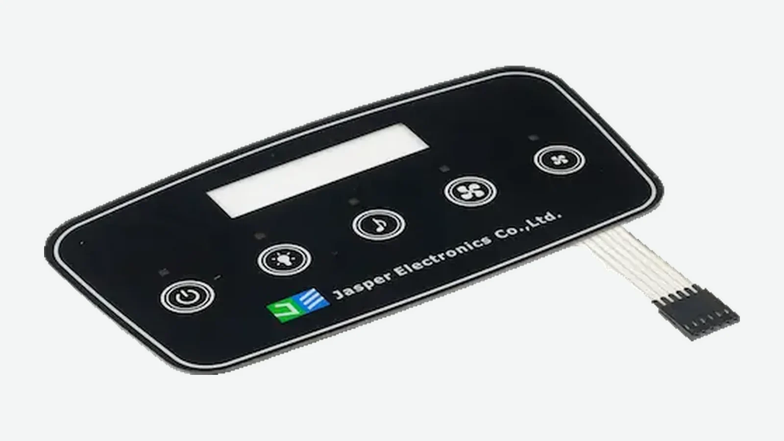
Integrated front panels that coordinate touch sensing, graphics, windows, lighting, carrier, and host connection.

Choose it when: Choose this route when one supplied front assembly should own several adjacent interface boundaries.

View Capacitive HMI Front Panels

A Capacitive Touch Panel Is an Installed Sensing System

A capacitive touch panel detects a change in an electric field through a decorative cover surface. The visible icon is only the operator cue; the working input also depends on electrode geometry, cover construction, spacing, routing, reference conditions, controller setup, nearby conductive parts, and software state.

Custom capacitive touch panels can provide fixed commands, multi-key layouts, sliders or wheels, display-linked coordinate input, illuminated icons, or a larger HMI front. Those formats should not be treated as interchangeable because they ask different questions of the sensing layout and host logic.

The production release should connect the front artwork to the sensing circuit, enclosure model, controller ownership, feedback plan, operator states, first article, and change-control record.

Custom capacitive touch panels fit when:

  • the product needs a clean front surface without openings around individual controls
  • graphics, sensing areas, lighting, and display windows must remain registered
  • operator and environmental states can be defined before controller tuning
  • the OEM can validate the complete installed panel with its host electronics

Choose the Route by the Input Model and Supplied Boundary

Start with the page that owns the hardest unresolved interface. A project may combine routes, but the drawing should still identify which area is discrete, coordinate-based, illuminated, display-aligned, or assembly-owned.

Product RoutePrimary Design QuestionEvidence to Approve
Capacitive touch switchesHow should each fixed command behave around neighboring metal, routing, feedback, and false-touch states?Electrode artwork, cover stack, installed enclosure, state table, and host response
Capacitive touch keypadsHow are multiple keys, channels, adjacent inputs, sliders, wheels, and disabled states mapped?Key map, channel map, simultaneous-input rules, feedback hierarchy, and installed sample
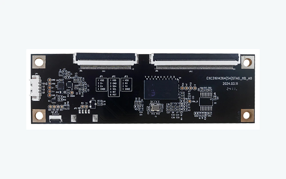
PCAP touch panelHow does coordinate input relate to the display, active area, controller, gestures, and host application?Sensor and display stack, active-area registration, controller files, and application validation
Panel with display windowCan sensing, print, window treatment, display opening, and bezel remain aligned?Artwork overlay, display and enclosure models, optical sample, and sensing verification
Backlit capacitive panelDo icons, light paths, sensing electrodes, and powered states work without confusing the operator?Day and powered-state sample, LED layout, light-block plan, and state behavior
Capacitive HMI front panelWho owns the carrier, circuit, lighting, windows, connector, assembly, and final functional check?Assembly drawing, interface list, test plan, installed first article, and revision control
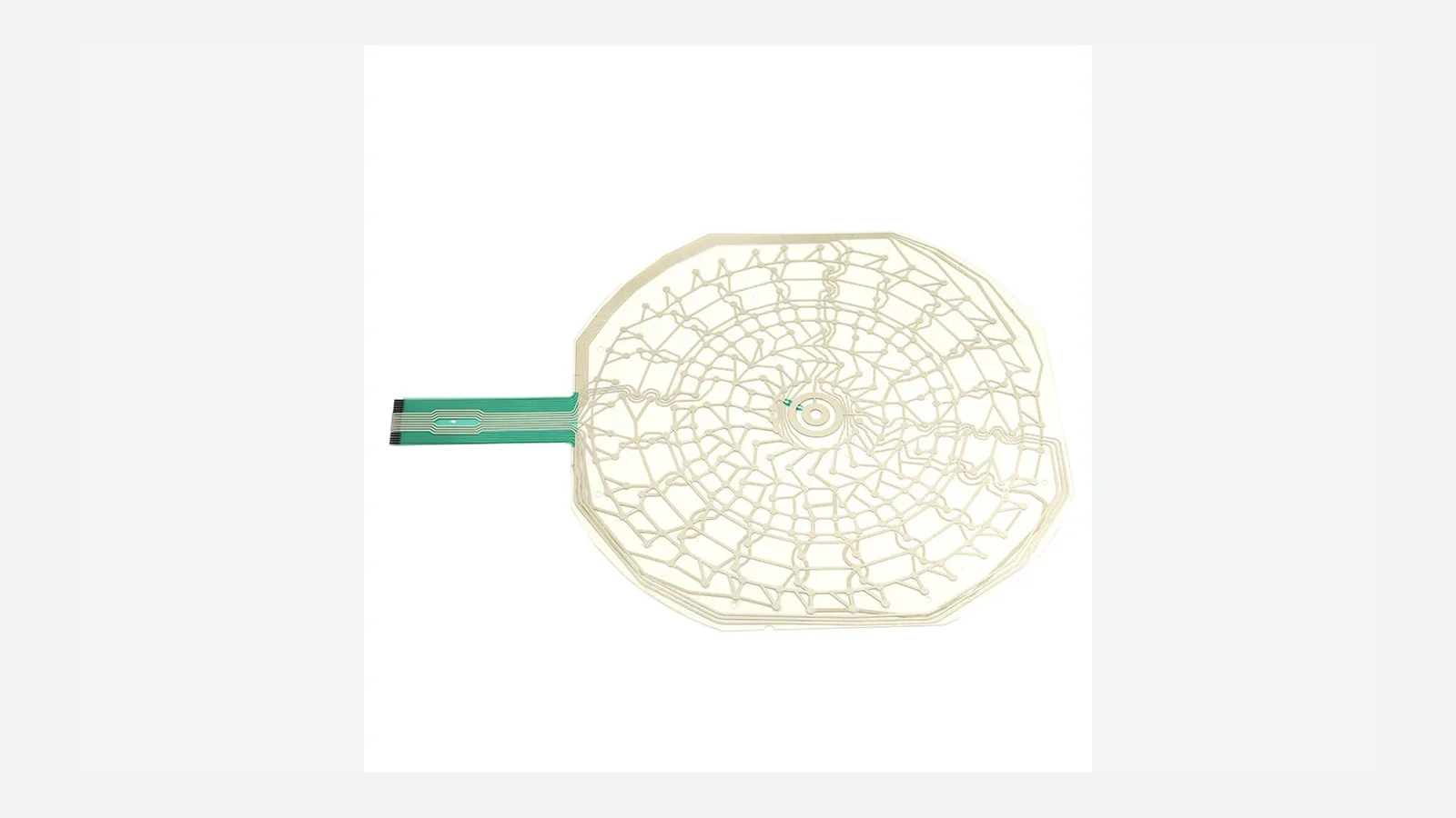
Capacitive switch electrodes beneath a printed sealed cover surface
FIELD AND COVER

Design the Electrode Through the Real Cover and Enclosure

The same electrode can behave differently after the decorative surface, adhesive zones, printed layers, air gaps, bezel, display, grounding, and nearby conductive parts are installed. Review the complete field boundary before sensing artwork is frozen.

  • identify every layer between the operator and electrode
  • mark conductive coatings, bezels, fasteners, displays, and grounded parts
  • keep sensing and routing geometry tied to enclosure datums
  • approve representative edge, corner, and crowded controls
PCAP panel beside fixed capacitive controls for input-model comparison
INPUT MODEL

Separate Fixed Commands, Key Arrays, and Coordinate Touch

A fixed switch, a keypad channel, a slider, and a display-linked coordinate surface produce different data for the host. Naming the input model early prevents controller assumptions from leaking into artwork and circuit decisions.

  • label each active region by function and input type
  • define allowed combinations and rejected combinations
  • assign wake, disabled, cleaning, and fault states
  • document which decisions belong to firmware, controller, and panel
Integrated capacitive HMI front panel with display, icons, and host connection
FEEDBACK AND HOST

Make Detection, Acknowledgment, and Action Three Explicit Events

A sensed touch does not automatically mean the command was accepted or executed. Lighting, sound, haptic response, display changes, and host actions should follow a released state model so the operator receives an honest result.

  • separate touch detection from host acceptance
  • define feedback for active, blocked, pending, and fault states
  • decide what happens when the host is asleep or disconnected
  • retain event traces during installed sample review

Release the Surface, Sensor, Controller, and Host States Together

01

Define the interaction

List fixed commands, keypad channels, sliders, wheels, coordinate areas, feedback, and operator states.

02

Close the installed stack

Align artwork, cover, adhesive, electrodes, display, nearby metal, enclosure features, and grounding concept.

03

Assign system boundaries

Name who owns sensing artwork, controller selection, tuning files, firmware filtering, host logic, and final validation.

04

Approve installed samples

Exercise intended touches, adjacent inputs, moisture and cleaning states, gloves, wake behavior, feedback, and blocked commands.

05

Control production revisions

Lock artwork, materials, circuit, controller file, assembly, inspection, retained sample, and retuning triggers.

Where Custom Capacitive Touch Panels Fit

The shared requirement is a sealed operator surface whose sensing, graphics, feedback, and host behavior can be validated as one installed interface.

01

Industrial equipment

Flat command panels, machine settings, status controls, and display-linked operator fronts.

02

Medical and laboratory devices

Wipe-clean control surfaces with deliberate active, disabled, cleaning, and alarm-related states.

03

Appliances and building controls

Integrated icons, key arrays, sliders, wheels, displays, and powered-state graphics.

04

Access and security products

Code entry, mode selection, status feedback, and controlled neighboring-key behavior.

05

Transportation and marine controls

Sealed front panels coordinated with gloves, moisture states, lighting, enclosure metal, and host logic.

06

Test and measurement

Dense front panels with display windows, fixed functions, channel selection, and revision-controlled legends.

Send the Front Panel, Electronics, and State Information Together

An early artwork layout, enclosure model, controller concept, and operator-state note are enough to begin a useful capacitive interface review.

  • panel outline, artwork, icon map, active regions, display windows, and available models
  • cover material stack, print layers, adhesive zones, coatings, and cosmetic expectations
  • electrode artwork, circuit route, connector, controller concept, grounding, and nearby metal
  • operator conditions including gloves, moisture, cleaning, held touch, and adjacent contact
  • feedback plan, lighting states, wake and disabled behavior, host actions, and fault handling
  • supplied assembly boundary, sample plan, production estimate, approval evidence, and change controls
Send Capacitive Panel Files

Capacitive Touch Panel FAQ

What is a custom capacitive touch panel?

It is a project-specific front surface whose sensing electrodes, cover, graphics, controller behavior, feedback, enclosure, and host states are developed around one OEM interface.

Which capacitive panel route should we choose?

Choose fixed switches for separate commands, keypads for mapped groups of discrete inputs, PCAP for coordinate interaction, display-window panels for optical alignment, backlit panels for powered graphics, or HMI fronts for a broader supplied assembly.

Can one panel combine several capacitive input types?

Yes, when each region has a defined input model, channel or coordinate ownership, routing boundary, feedback behavior, and host rule. The combined installed sample should be the approval reference.

What causes false or missed touches?

Common causes include an incomplete cover stack, crowded electrodes, routing coupling, nearby conductive parts, uncontrolled grounding, moisture states, enclosure changes, or host filtering that does not match the intended interaction.

What should be approved before production?

Approve appearance, sensing behavior, adjacent controls, operator states, feedback, display alignment, host response, assembly fit, controller files, inspection method, and revision ownership.

Capacitive Touch Engineering Resources

Review the capacitive field in the real front-panel assembly.

JASPER can review the panel route, artwork, cover, electrodes, lighting, windows, enclosure interfaces, controller boundary, host states, and production evidence as one custom capacitive touch panel project.

Start Capacitive Panel ReviewContact Engineering