
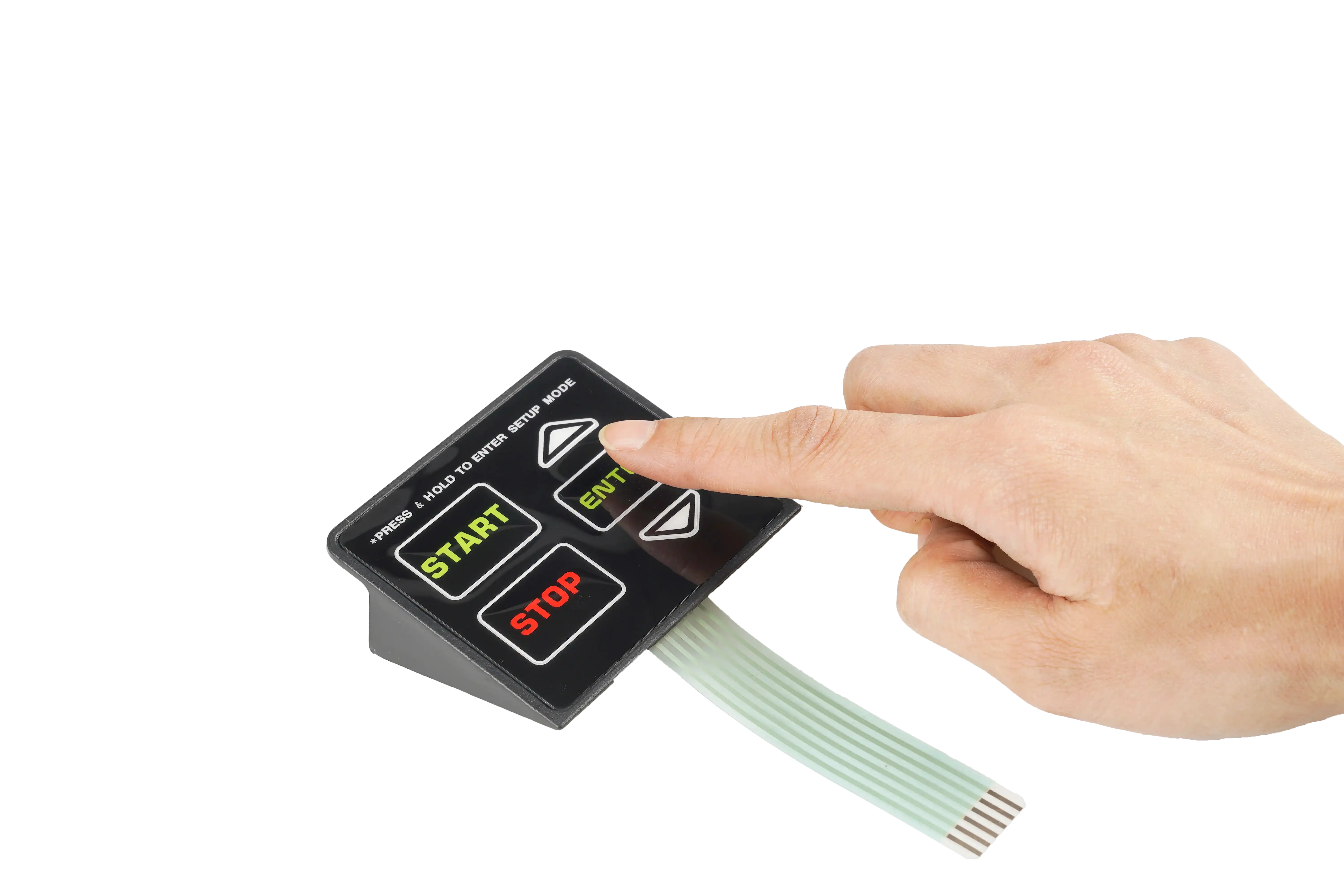
Membrane Switch Design Guide
Review the complete stack, key layout, tail, connector, tactile, lighting, and enclosure decisions.
Read GuideCustom membrane switches combine the printed overlay, spacer, circuit, tactile or non-tactile keys, flexible tail, connector, adhesive, and enclosure fit in one OEM interface.
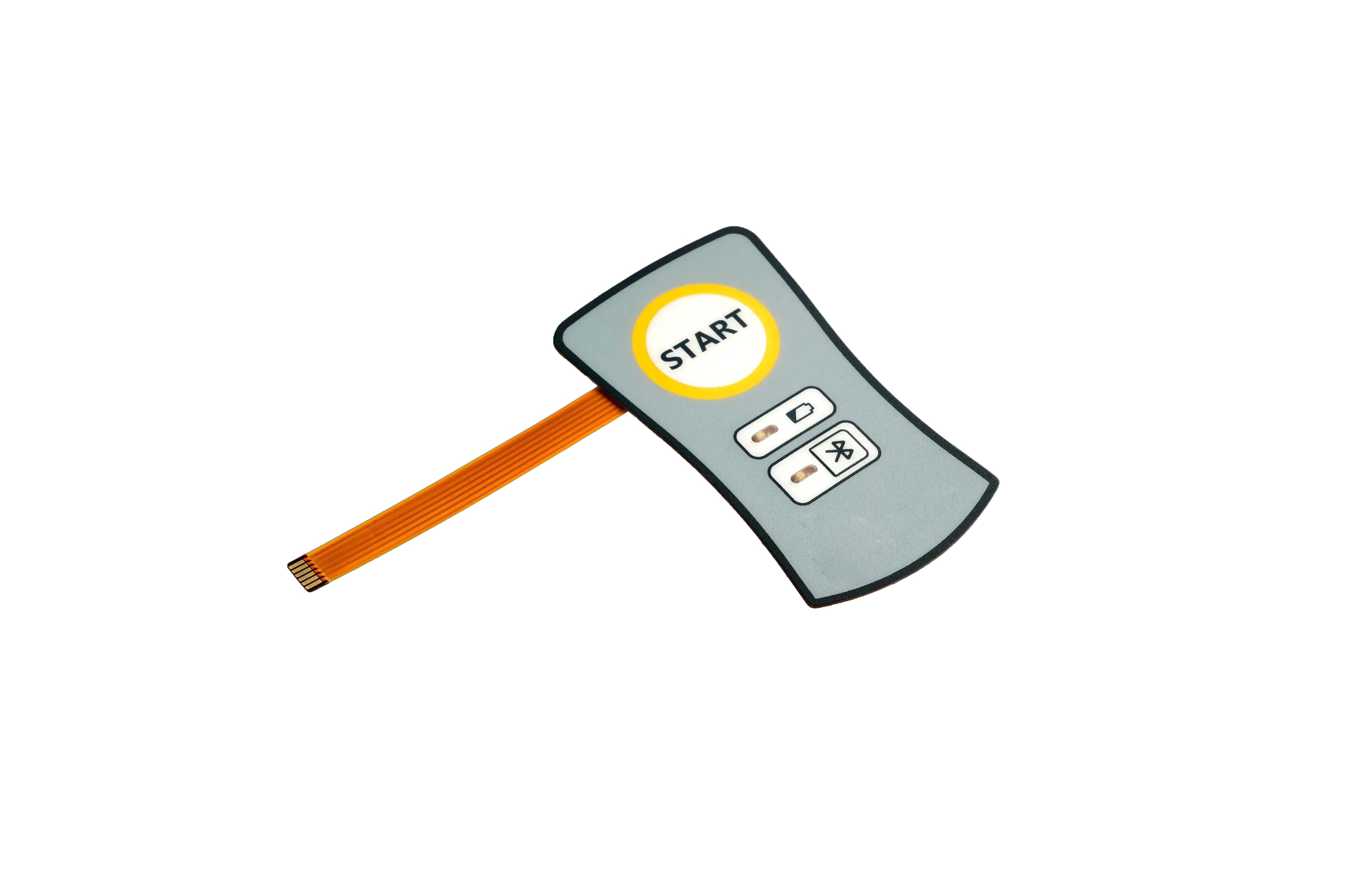
Engineering Review + Compliance Planning
Drawing review | stack definition | sample validation | production release
A custom membrane switch is a low-profile electrical switch assembly built around a printed graphic overlay and flexible circuit. The geometry, artwork, key feel, tail, connector, lighting, adhesive, and sealing details are developed for the buyer's enclosure.
Unlike a standard keypad, the complete stack is controlled by the OEM drawing. That makes it possible to combine display windows, dead-front icons, tactile or non-tactile keys, LEDs, shielding, and custom circuit routing in one bonded interface.
The best custom membrane switch projects are reviewed inside the real enclosure before tooling. That exposes tail, connector, window, adhesive, and key-feel conflicts while they are still inexpensive to correct.
Use these common capability ranges as an early design reference. Final dimensions, tolerances, materials, and testing are confirmed against the approved drawing and application.
| Feature | Typical Options | Design Review Focus |
|---|---|---|
| Overlay | PET or polycarbonate | Finish, flex life, chemicals, windows, embossing |
| Circuit | Printed silver, carbon, PCB, or FPC | Matrix, resistance, shielding, components, test pads |
| Key Feedback | Tactile or non-tactile | Force curve, dome size, key pitch, operator workflow |
| Lighting | LED, light guide, or dead-front icons | Brightness, leakage, polarity, voltage, viewing angle |
| Tail and Connector | ZIF, pin header, crimp, solder tabs, custom | Exit direction, bend radius, housing clearance |
| Sealing | Application-specific perimeter and tail sealing | Adhesive land, enclosure flatness, venting, IP target |
| Testing | Continuity, resistance, actuation, visual, functional | Controlled criteria, fixture, sampling plan, records |
Production Tip: approve the switch in the final enclosure with the real connector, display, cleaning method, and installation pressure.
Send the outline, key map, tail direction, connector, environment, and quantity. Engineering review can identify stack conflicts before sample tooling.
Send Drawing
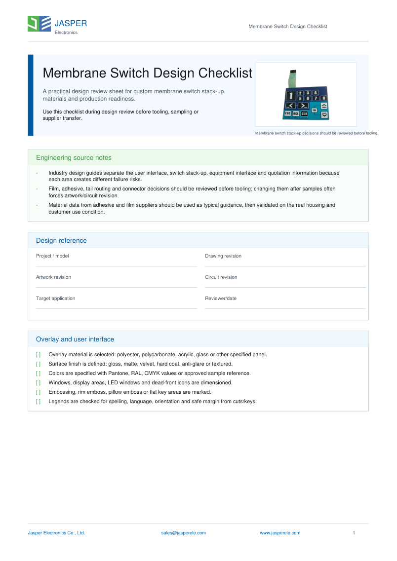
Use the design guide to review overlay film, spacer venting, circuit routing, tactile feel, backlighting, adhesive, tail, and connector decisions.
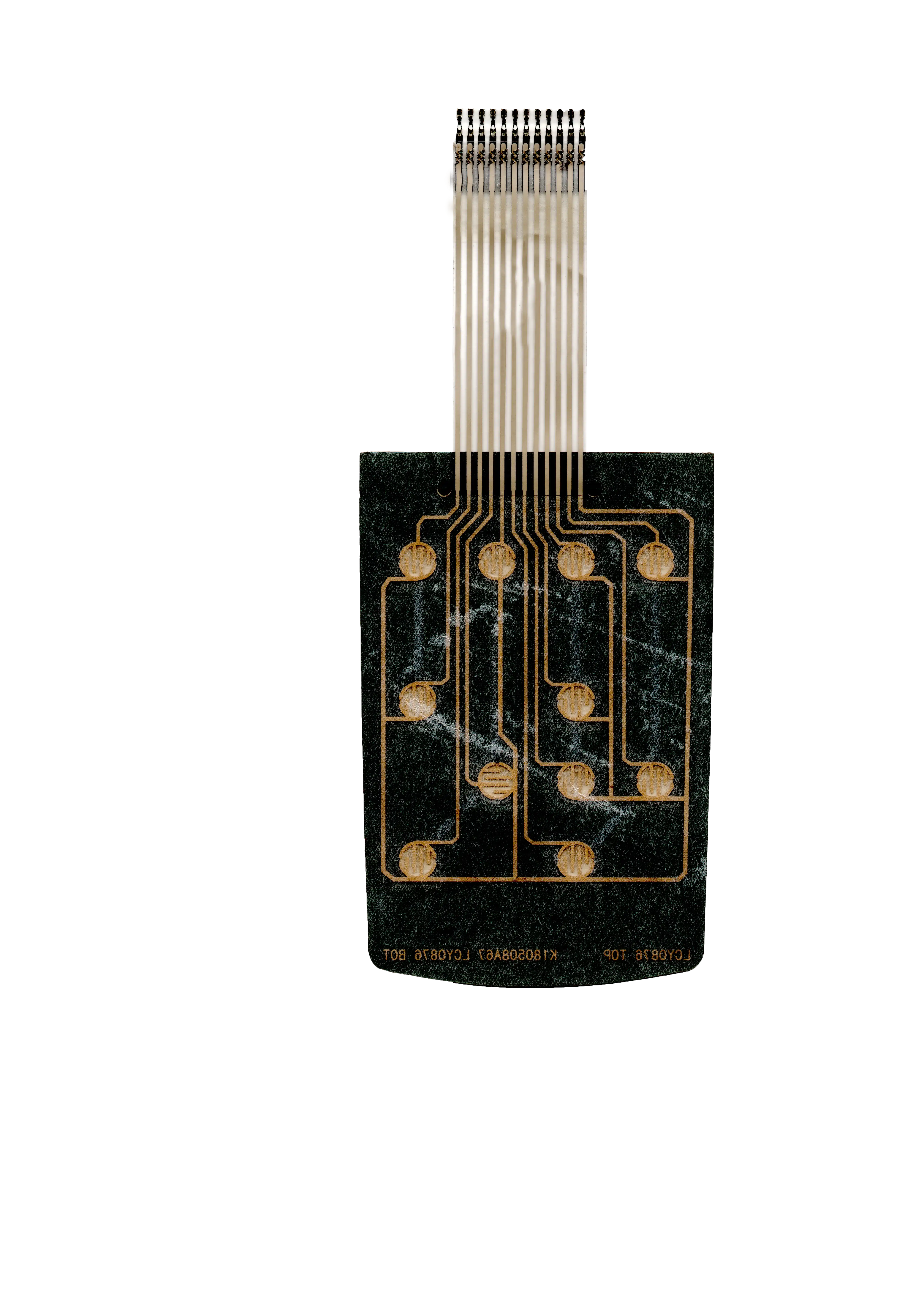
Material selection affects appearance, flex life, chemical resistance, actuation feel, adhesion, electrical performance, and assembly yield.
Surface treatment should be selected around readability, cleaning, glare, scratch exposure, branding, and the user's interaction with the key areas.
| Gloss | High clarity and saturated printed color |
|---|---|
| Matte | Reduced glare for operator panels |
| Textured | Improved handling and controlled appearance |
| Selective Gloss | Gloss windows or icons within a matte panel |
| Hard Coat | Additional abrasion and chemical resistance |
| Dead Front | Icons or legends visible only when illuminated |
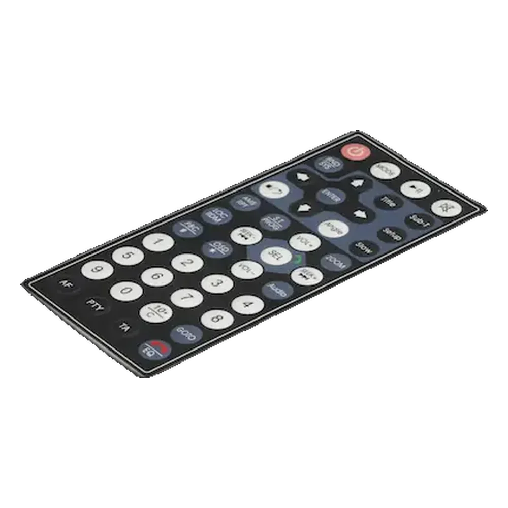
Inspection requirements are agreed before production so cosmetic, electrical, tactile, dimensional, and assembly criteria use the same approved standard.
Prototype builds focus on fit, artwork, tactile feel, lighting, tail routing, and enclosure assembly. Production manufacturing adds controlled materials, revision records, inspection fixtures, packaging, and repeatability requirements.
Start Production ReviewUse practical checklists for the drawing package, material selection, connector routing, waterproof design, and sample approval.
Request DFM Review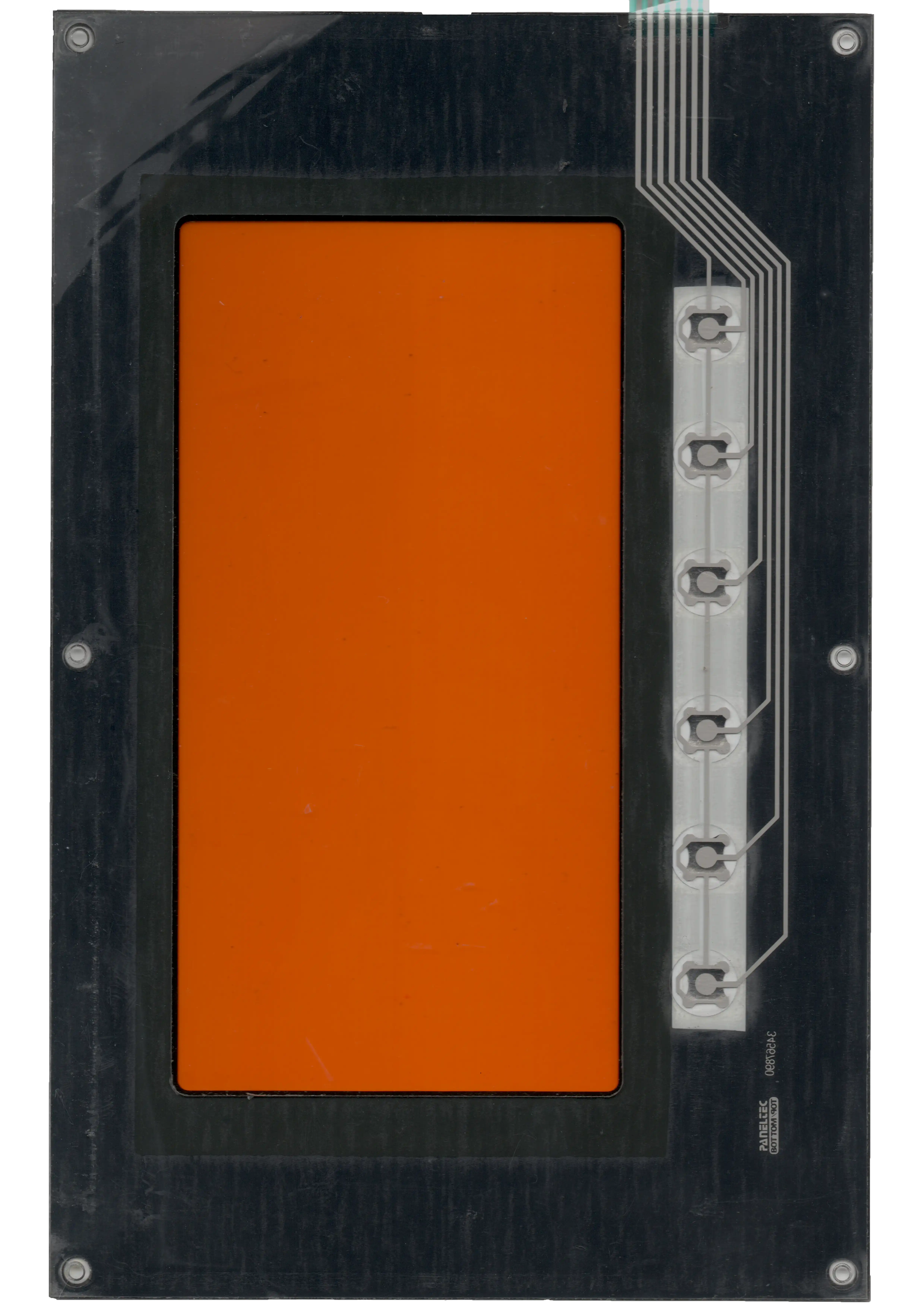
The printed overlay defines the visible interface and protects the layers below. A spacer creates the controlled air gap between the upper and lower circuit contacts. Pressing a key flexes the overlay or metal dome so the conductive contacts close the assigned circuit.
The circuit routes each key to a flexible tail and connector. Tactile versions use metal domes or formed structures for snap feedback. Non-tactile versions rely on overlay travel and external visual, audible, or software confirmation.
Lighting, shielding, display windows, adhesives, and sealing layers are added around the switching structure. The final assembly is bonded to the enclosure, so surface flatness, tail clearance, connector position, and installation pressure directly affect performance.
Send the panel outline, key map, artwork, tail exit, connector or pinout, enclosure surface, environment, quantity, and sample target. Early drawings are useful even when every tolerance is not final.
PET is commonly selected for repeated flex, chemical exposure, and durable key areas. Polycarbonate can suit selected graphic or forming requirements. The final choice depends on finish, embossing, cleaning, windows, and life expectations.
Yes. Release component height, voltage, current, polarity, grounding, connector, pinout, enclosure clearance, and test criteria so the added electrical features match the mechanical stack.
Review the complete installed boundary: perimeter adhesive, corners, cutouts, tail exit, venting, connector area, housing flatness, cleaning exposure, and the exact IP or splash target.
Approve artwork, color, texture, windows, key feel, force consistency, LED states, tail routing, connector access, adhesive fit, enclosure alignment, and the agreed electrical and visual checks.
Yes. Prototype work validates the design and installed fit. Production release adds controlled files, materials, fixtures, inspection limits, lot records, packaging, and change control.
Review the complete stack, key layout, tail, connector, tactile, lighting, and enclosure decisions.
Read Guide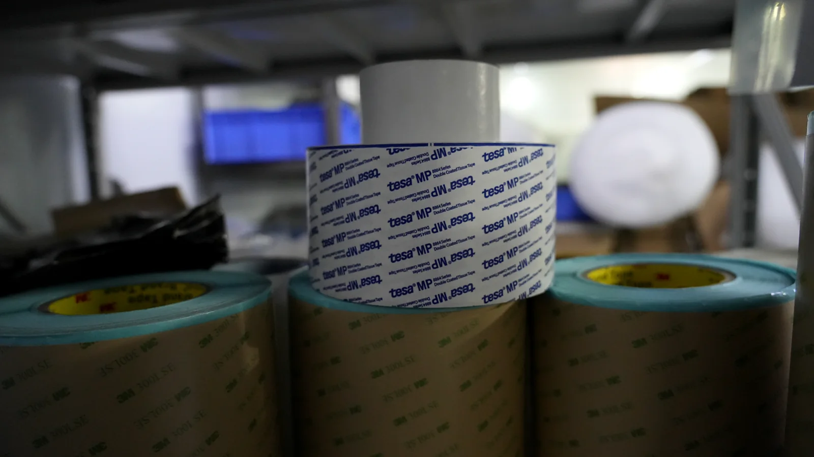
Compare overlay films, circuits, spacers, domes, adhesives, shielding, and connector options.
Read Guide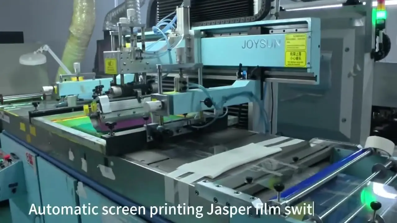
Prepare the drawing, quantity, environment, testing, sample, and production information for quotation.
Read GuideGet an online quote and membrane switch design analysis today.
Get a QuoteShare the project basics. JASPER will review the stack, materials, connector, quantity, and production risks.