
Membrane switch adhesive selection starts with the mating surface and the installed environment, not with a catalog “strongest tape” claim. Match stack role (front, spacer, rear mounting), substrate energy, texture, edge land, temperature, moisture, chemistry, pressure, and dwell—then prove the bond on the real enclosure. Adhesive alone does not create an IEC 60529 IP rating.
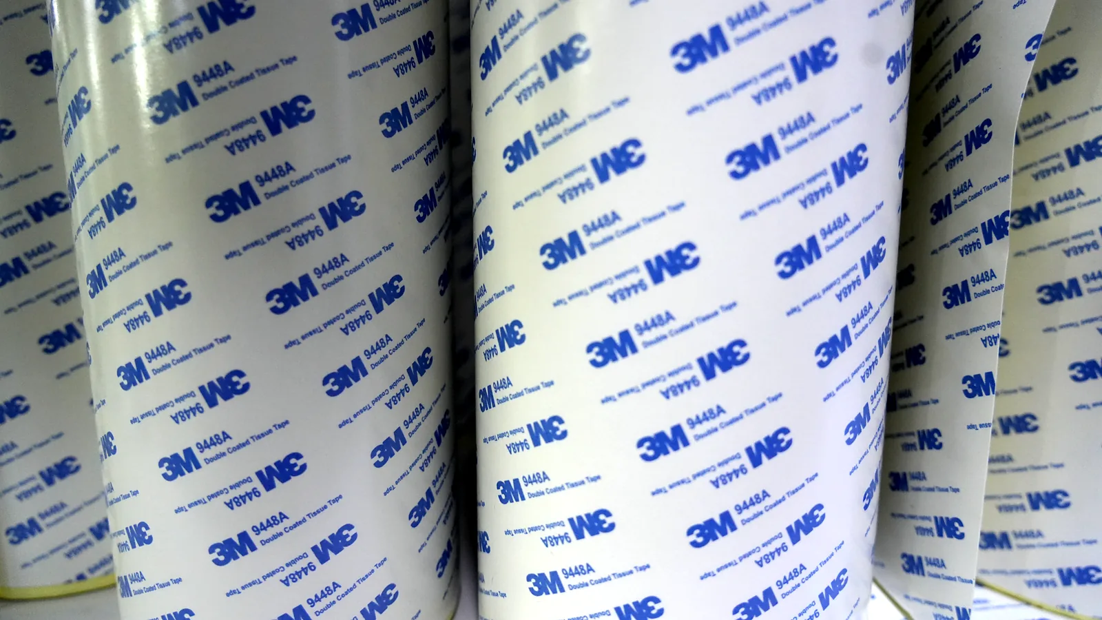
This guide is written for OEM mechanical, packaging, and quality engineers who must release a custom membrane switch stack to tooling and first-article assembly. It treats adhesive as a converted engineering layer. Named grades such as 3M 467MP, 3M 468MP, and 3M 9495LE (300LSE) appear only as supplier-positioned examples from 3M Technical Data Sheets, not as universal defaults. Review enclosure material and surface finish with the switch drawing, then validate the selected acrylic PSA on production-intent ABS, PC, PET, powder-coated steel, or stainless-steel surfaces.
1. Why Membrane Switch Adhesive Selection Matters
Wrong membrane switch adhesive selection rarely fails on the sample table under ideal pressure. It fails weeks or months later as edge lift on a powder-coated steel door, bubbles under a polycarbonate (PC) display window, polyester (PET) overlay edges that creep, paint that peels with the switch, or a perimeter path that opens after washdown. Field teams often write “switch failure.” The root cause is frequently membrane switch bonding: incomplete wet-out, coating release, peel stress at a short land, or a construction chosen for a smooth ABS coupon and installed on a textured polypropylene (PP) or polyethylene (PE) housing.
The cost is not only scrap panels. A bond change after steel-rule die tooling can force new die cuts, new liner splits, new first-article inspection (FAI) samples, and a re-run of humidity or thermal checks that should have been locked with the enclosure finish. If the assembly carries an IP65/IP67-style target or a silicone gasket stack, the problem multiplies: teams sometimes widen adhesive hoping to “buy” sealing. IEC 60529 classifies protection for enclosures and defined test articles, not for a loose membrane switch or a single adhesive strip (Source: IEC 60529). Adhesive width is one input among edges, flex tail exit, ZIF connector clearance, vents, compression, fasteners, and assembly quality.
Commercial pages and short blogs often reduce the decision to “use 3M 467MP on metal and 3M 300LSE on plastic.” That split is a useful starting map from 3M product positioning, but it skips mold release, powder-coat chemistry, curvature, land width, isopropyl alcohol (IPA) or alkaline cleaner residues, and the difference between front, spacer, and rear layers. The rest of this article gives a nine-point framework, decision tables, a process sequence, and explicit cases where acrylic pressure-sensitive adhesive (PSA) rear mount is the wrong construction.
2. The Nine-Point Evaluation Framework for Membrane Switch Adhesive Selection
Use these nine criteria in order. Each one can veto a grade that looked fine on a datasheet alone.
2.1 Stack role: front, spacer, rear, or foam-gasket
Membrane switch bonding is not one adhesive job. The same acrylic chemistry can succeed as a spacer film and fail as a rear mount if the enclosure is rough or low-energy.
| Stack role | What it joins | Primary risks if mismatched |
|---|---|---|
| Front / overlay adhesive | Graphic overlay to circuit or dome carrier | Window contamination, edge lift at emboss, optical haze |
| Spacer adhesive | Separates circuit layers; defines key openings | Unintended contact, heavy actuation, misregistration |
| Rear mounting adhesive | Finished switch to enclosure | Edge peel, incomplete wet-out, coating release |
| Foam / gasket bonding | Gap fill, compression, seal assist | Creep, uneven compression, false IP assumption |
Drawing names each adhesive layer by role, material family, and adhesive-free zones (windows, LEDs, vents, tail).
One “3M tape” callout for every layer with no role map.
2.2 Substrate material and surface energy
Surface energy influences wet-out. It does not by itself prove a bond. Bare metals and glass often behave as higher-surface-energy surfaces when clean; many polyolefins, some filled plastics, and powder-coated paints behave as low-surface-energy or difficult surfaces (Source: 3M substrate surface consideration; 3M LSE plastics bonding resources).
Supplier-positioned examples used in membrane switch work:
| Enclosure / face condition (examples) | Construction family often evaluated first | Example grades (not defaults) | Evidence still required |
|---|---|---|---|
| Smooth aluminum, steel, glass, many HSE plastics (ABS, PC when clean) | 200MP acrylic transfer tape | 3M 467MP | Actual paint/oxide, cleaner, pressure |
| Textured metal or irregular HSE surface | Thicker 200MP transfer construction | 3M 468MP family | Texture depth, land width, wet-out sample |
| Powder-coated metal, many LSE plastics (PP, PE, some TPOs), difficult paints | 300LSE acrylic family | 3M 9495LE / 300LSE constructions | Coat adhesion, mold release, dyne if measured |
| Soft foam or defined gap | Foam-supported double-coated construction | Project-selected foam PSA | Compression set, edges, seal design |
| Service-removable interface | Documented removable construction | Only with written residue/damage limits | Access method, replacement process |
3M positions 467MP (200MP) for metals and high-surface-energy plastics, and 9495LE (300LSE) for many low-surface-energy plastics and powder-coated paints (Sources: 3M 467MP TDS; 3M 9495LE product data). Avery Dennison Performance Tapes likewise markets membrane-switch spacer and switch-plate films for overlay, circuit, and dome-retainer bonds, including low-surface-energy material cases (Source: Avery Dennison membrane switch tapes). None of these lines replace a sample on the production enclosure.
RFQ lists resin grade or paint system, not only “plastic” or “metal.”
LSE label used as a magic word without identifying the actual molded resin, additives, or powder-coat system.
2.3 Membrane switch mounting adhesive vs internal laminating adhesive
Membrane switch mounting adhesive is the rear construction that carries service peel, vibration, thermal expansion mismatch, and cleaning attack at the enclosure. Internal laminating adhesives (front and spacer) mainly see stack stresses and converting geometry.
Mounting decisions should include:
- Enclosure flatness and local steps under the switch footprint
- Continuous perimeter land versus interrupted lands at cutouts
- Tail exit and connector clearance so the adhesive face is not compromised at the flex
- Whether the enclosure is painted before or after switch install (coating cure and cleanliness)
Mounting adhesive is specified against the enclosure drawing revision, not against a generic coupon.
Mounting adhesive selected only from the switch BOM without enclosure finish data.
2.4 Texture, roughness, and flatness
Texture reduces intimate contact. Deep grain, orange peel on powder coat, EDM texture on aluminum tooling faces, or as-molded sink on ABS/PC housings can leave air paths that look fine at first touch and open under thermal cycling. Flatness errors create peel at high spots and voids in low spots. A thicker 200MP transfer tape (for example, constructions in the 3M 468MP family) or a foam-supported acrylic face can help conform, but it also changes stack height, metal-dome travel, and edge appearance.
Texture callout or Ra/finish class is shared; samples use production-intent powder-coat or molded surfaces, not only 304 stainless coupons.
Smooth coupon approval for a textured production housing.
2.5 Geometry: curvature, steps, and edge land width
Permanent bend, emboss returns, and steps create peel stress. Narrow adhesive lands at the panel edge or around large windows concentrate that stress. Continuous land width around the perimeter and critical openings often matters more than adding another internal layer. There is no universal millimeter rule that replaces the enclosure drawing and sample peel path.
Edge land and window adhesive-free zones are dimensioned; sharp adhesive corners are avoided in die design.
Zero-land corners, knife-edge perimeters, or adhesive that stops short of the seal path while marketing claims “sealed.”
2.6 Temperature and thermal cycling
State temperature as a project requirement: storage, operating, and any process heat (nearby powder-coat cure ovens, ultrasonic welding of ABS housings, outdoor cabin heat on painted steel). Acrylic PSAs such as 3M 200MP and 3M 300LSE families are widely used on industrial control panels and appliance interfaces, but grade limits and dwell behavior differ. Do not copy an unverified temperature table into the AutoCAD or PDF drawing without the current Technical Data Sheet (TDS) for the selected 3M grade and a sample plan under IEC-style environmental exposure if the product requires it.
Min/max temperatures in °C and cycle profile appear in the RFQ with the adhesive candidates (467MP, 468MP, 9495LE, or alternate).
“High temperature adhesive” with no °C values and no named grade.
2.7 Moisture, cleaners, and process chemistry
Name the cleaning process: IPA wipe, alkaline cleaner, quaternary disinfectant, cutting oil, salt spray, outdoor UV, or food-industry washdown. Plasticizers from soft PVC, mold release on PP/PE, or silicone overspray can block wet-out or attack the acrylic bond line later. Moisture that reaches an open edge at a PET tail exit is an assembly and enclosure problem as much as a chemistry problem—pair adhesive review with gasket and fastener design when IP65/IP67-class validation is planned under IEC 60529.
Cleaner chemistry and frequency are listed; FAI sample prep matches production cleaning on the same powder coat or molded ABS lot.
Assumption that any PSA resists every hospital disinfectant or degreaser.
2.8 Application pressure, dwell, and liner sequence
Pressure-sensitive adhesives need contact and time. 3M surface-preparation guidance emphasizes clean, dry, unified surfaces and firm application pressure (Source: 3M surface preparation guidance). Production instructions should define:
- Wipe method (for example, lint-free wipe with a project-approved solvent such as IPA when compatible) and dry time
- Liner peel direction and split-liner sequence for large PET/PC overlays
- Rubber roller or pneumatic press pressure and number of passes
- Dwell before mechanical load, shipping, thermal shock, or humidity test
- Fixture needs for large graphic overlays or flexible tails into ZIF connectors
Work instruction matches the FAI sample that passed under the same 3M grade lot family.
Hand-smoothed install in production after a vacuum-press sample.
2.9 Validation evidence on the real enclosure
Datasheet peel on stainless steel is not the same as peel on the customer’s powder coat. Validation should use production-intent enclosures or panels, defined pressure/dwell, and a written accept/reject method (visual edge lift, bubble criteria, peel path inspection, continuity retest after environmental exposure as required by the project). 3M TDS values for 467MP or 9495LE are screening data; they do not replace FAI on the painted CRS door or molded PP housing.
Link validation to the manufacturer’s quality and testing process when third-party or in-house checks under the purchase order quality plan (for example, ISO 9001-controlled inspection records) are required.
First-article package includes enclosure finish ID, 3M adhesive lot, process parameters, and photos of bond edges.
“Looks stuck” sign-off with no method.
3. Stack Diagram: Where Adhesive Sits in Membrane Switch Bonding
Graphic overlay (PC / PET, hard coat, print)
front / overlay adhesive
Dome carrier / upper circuit (optional metal domes)
spacer adhesive (openings for keys)
Lower circuit / flex tail
rear mounting adhesive ← membrane switch mounting adhesive
Enclosure: metal / plastic / paint / powder coat / glass
optional foam gasket / mechanical fasteners / sealed bezel
Read the diagram bottom-up for field failures: most “switch came off” reports start at the rear mount and enclosure finish. Read it top-down for converting failures: windows, emboss, and spacer openings.
4. Failure-Chain Table
| Observed symptom | Likely chain | First checks |
|---|---|---|
| Edge lift after weeks | Peel stress + short land + incomplete wet-out or LSE surface | Enclosure finish, land width, pressure/dwell, grade family |
| Bubbles under overlay | Lamination sequence, particles, premature contact, texture | Cleanroom/handling, liner sequence, fixture, adhesive-free windows |
| Paint/coating on adhesive face | Coating adhesion failure, not only adhesive cohesion | Cross-hatch/coating cure; change coating or mechanical assist |
| Soft keys / dead keys after bond | Spacer crush, excess stack pressure, misregistration | Spacer thickness, press recipe, registration |
| Moisture under panel | Open edge path, tail exit, vent, gasket gap—not “weak tape” alone | Enclosure IP design, continuous land, assembly torque |
| Residue on removal | Construction not designed for service removal | Removability requirement never documented |
Inspect both faces of a failed bond before changing materials. Adhesive remaining on one side only is a different story from clean separation with coating flakes.
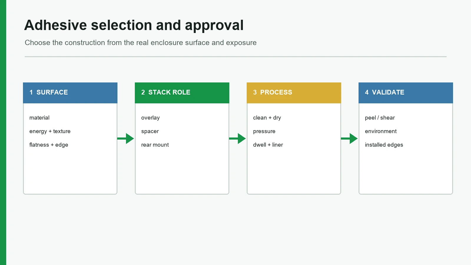
5. Step-by-Step Selection and Approval Process
Step 1 — Freeze the enclosure surface
Collect resin grade (for example, ABS, PC, PP, PE, nylon) or metal type (aluminum, stainless steel, cold-rolled steel), paint or powder-coat system, texture, flatness notes, and the drawing revision that will ship. If the enclosure is still “unspecified plastic,” membrane switch adhesive selection is not ready for steel-rule die tooling freeze.
Step 2 — Map stack roles
List front, spacer, rear, and any foam layers. Assign which face is optical (LED/LCD window in the graphic overlay), which is sealing-critical, and which is mounting-critical. Keep internal laminating adhesives separate from membrane switch mounting adhesive on the BOM and in the 3M (or alternate) grade callouts.
Step 3 — Shortlist constructions from surface energy and environment
Use the substrate table in §2.2 as a shortlist, not a release. Prefer supplier-primary TDS language for candidate grades—3M 467MP / 468MP (200MP) versus 3M 9495LE / 300LSE families, or equivalent Avery Dennison spacer/switch-plate films when the converter standardizes on that line. Include cleaner and temperature inputs in °C before locking a grade.
Step 4 — Design converted geometry
Die-cut windows, LED holes, emboss clearances, flex tail keep-outs, and liner splits. Adhesive geometry is part of the product, not an afterthought for the operator with a knife on a PET liner.
Step 5 — Build samples on production-intent surfaces
Apply with documented pressure, dwell, and cleaning. Include at least one sample that sees realistic handling and, if required, thermal or humidity exposure defined by the project—not a single warm finger press on a polished 304 stainless coupon.
Step 6 — Run accept/reject and record lots
Define edge inspection, bubble limits, continuity retest after mount, and any 90°/180° peel or shear method the quality plan requires. Record adhesive lot, liner type, and process parameters. Route formal checks through the agreed testing plan.
Step 7 — Lock drawing and work instruction together
Release only when the PDF/DXF drawing, BOM grade (for example, 3M 467MP or 9495LE), and assembly instruction match the FAI sample that passed. A drawing change without a process change is an incomplete release.
5a. Sample Approval Checklist (RFQ inputs)
| Input | Why it matters | Example of a usable answer |
|---|---|---|
| Enclosure material | Sets HSE vs LSE shortlist | “Powder-coated CRS door, black matte” |
| Surface energy / finish data | Guides 200MP vs 300LSE trial | “Powder coat; no dyne data; send 3 panels” |
| Texture / flatness | Drives thickness/foam choice | “Orange-peel powder; flat within drawing note” |
| Edge land width | Peel path and sealing land | “Continuous ≥ specified land on DWG Rev C” |
| Cleaners | Chemistry attack / residue | “IPA wipe only before install” |
| Temperature °C | TDS screen | “0–50 °C operate; −20 °C storage” |
| Stack roles | Front vs rear grades | “Front 467MP; rear 9495LE candidate” |
| Install process | Transfers sample to production | “2 kg roller, 3 passes, 24 h dwell” |
| Removability | Permanent vs serviceable | “Permanent; field replace whole panel” |
| Validation method | Accept/reject | “Visual edge + continuity after 48 h” |
Send this table filled in with the enclosure material and surface finish when requesting adhesive review.
6. Release Blockers That Disqualify a Construction
These override a low unit price or a familiar grade name.
- No enclosure finish on the RFQ — selecting adhesive against “metal or plastic” is guessing.
- IP claim based only on adhesive width — conflicts with IEC 60529 system framing.
- Smooth coupon used to approve textured or powder-coated production parts.
- Single adhesive callout for front, spacer, and rear.
- Production install method differs from sample method (hand vs press, different cleaner).
- Coating that fails adhesion tests — adhesive cannot fix a coating that releases.
- Removable service requirement with a permanent high-tack construction and no residue plan.
- Universal life or biocompatibility claims for a component adhesive without finished-device validation context.
7. When Pressure-Sensitive Rear Mount Is Not the Best Choice
PSA rear mount is common and effective for many flat industrial panels. It is not always the right construction.
Prefer mechanical capture, a bezel, a rigid aluminum or FR4 subpanel, or a hybrid (adhesive + fasteners) when:
- The enclosure is deeply textured or discontinuous under the switch footprint
- Service removal is frequent and residue is unacceptable
- High peel loads exist at curved edges or large unsupported spans
- Washdown or outdoor design depends on silicone gasket compression and fasteners rather than acrylic PSA alone
- The powder-coat or wet-paint system is still changing in pilot builds under ISO 9001 prototype control
In those cases, 3M or Avery Dennison films may still appear inside the switch stack (front/spacer on PET/PC) while mounting duty moves to hardware. Document that split on the DXF/PDF drawing so buyers do not assume the rear PSA carries the full structural load.
8. Frequently Asked Questions
What is membrane switch adhesive selection?
Membrane switch adhesive selection is the engineering decision that matches each adhesive layer—front, spacer, and rear mounting—to substrate energy, texture, geometry, environment, and assembly process. The output is a documented construction and sample method, not a single “strongest tape” brand claim.
Which membrane switch mounting adhesive should be used on powder-coated metal?
Powder-coated metal is often treated as a difficult or low-surface-energy case. Supplier literature positions 300LSE-family constructions such as 3M 9495LE for many powder-coated paints and LSE plastics. Confirm on the actual powder system with production pressure and dwell; coating adhesion still limits the joint.
Is 3M 467MP always correct for metal enclosures?
No. 3M positions 467MP (200MP) for metals and high-surface-energy plastics when surfaces are suitable. Oil, oxidation, texture, or powder coat can move the problem into a different family. Treat 467MP as a common example, not a permanent default.
What is a low surface energy adhesive in this context?
A low surface energy adhesive is a PSA system formulated to wet difficult plastics and coatings better than standard HSE acrylics. In membrane switch work, 300LSE-family products are the usual example category. Measurement of surface energy helps, but resin, mold release, and texture still control the result.
Does membrane switch bonding make the panel waterproof?
No. Ingress performance depends on the complete enclosure, edges, tail exit, vents, gaskets, fasteners, assembly, and validation under IEC 60529 methods for the defined test article. Adhesive is one sealing contributor, not an IP rating by itself.
How should front adhesive differ from rear mounting adhesive?
Front adhesive must protect windows and support emboss/optics; rear mounting adhesive must wet the enclosure and survive service peel and environment. They may share a chemistry family, but geometry, thickness, and substrate targets often differ and should be specified separately.
What information is required for an adhesive review?
Provide enclosure material and coating, texture, flatness or curvature, edge land, cleaners, temperature requirements, assembly sequence, removability needs, quantity, and the switch stack drawing. Representative production parts beat generic coupons.
Can textured enclosures be bonded with PSA?
Sometimes, with a thicker or foam-supported construction and controlled pressure. Texture reduces contact area. If wet-out remains incomplete on production samples, change the enclosure finish, add mechanical capture, or both.
Who should own adhesive lot and process control?
The party that installs the switch should control cleaning, pressure, dwell, and lot records. If the membrane switch manufacturer ships with liner for customer install, the work instruction must travel with the part; otherwise sample results will not transfer.
9. What to Do Next
Membrane switch adhesive selection is a surface-and-environment decision executed through stack roles, converted geometry, and sample proof. Use the nine criteria, the substrate shortlist table, and the failure-chain checks before freezing tooling. Send the enclosure material, surface finish, texture notes, cleaner list, temperature requirements, and switch drawing for review so rear mounting adhesive and internal laminating layers can be matched to the real interface rather than a universal bond claim.
Manufacturers such as JASPER, alongside converters that build to 3M or Avery Dennison film systems and peer fabricators in the same OEM channel, can only be as accurate as the enclosure data provided. Where a pressure-sensitive rear mount is not the right structure, say so early and move load into bezels, fasteners, or rigid backers.
Technical References
- Source: 3M 467MP 200MP adhesive transfer tape technical data. Accessed 2026.
- Source: 3M 9495LE 300LSE double-coated tape technical data. Accessed 2026.
- Source: 3M substrate surface and bonding preparation guidance. Accessed 2026.
- Source: Avery Dennison membrane switch spacer technical guidance. Accessed 2026.
- Source: ASTM D3330 pressure-sensitive tape peel adhesion test method. Accessed 2026.
- Source: ASTM D1000 pressure-sensitive tape test methods. Accessed 2026.
- Source: IEC 60068 environmental testing method series. Accessed 2026.
- Source: IEC 60529 enclosure protection classification. Accessed 2026.
- Source: IEC 60529 — Degrees of protection provided by enclosures (IP Code). Accessed 2026.
- Source: 3M Adhesive Transfer Tape 467MP (200MP) technical data. Accessed 2026.
- Source: 3M 9495LE / 300LSE product positioning for LSE plastics and powder-coated paints. Accessed 2026.
- Source: 3M — Substrate Surface Consideration for Adhesive Selection. Accessed 2026.
- Source: 3M — Bonding Low Surface Energy plastics. Accessed 2026.
- Source: 3M surface preparation guidance (clean, dry, unified surfaces; firm pressure). Accessed 2026.
- Source: Avery Dennison Performance Tapes — Membrane switch spacer / switch-plate films. Accessed 2026.
Match the adhesive to the real enclosure
Send the substrate material, finish, texture, edge geometry, temperature, moisture, cleaners, assembly pressure, and sample test plan.