
How do membrane switches work? A membrane switch closes a defined electrical path when pressure on a printed key area flexes a contact layer or metal dome through a spacer opening onto a lower circuit, then routes that signal through traces, a flexible tail, and a connector to host electronics.

1. Definition and Canonical Stack
A membrane switch is a custom switch assembly that opens or closes a conductive path in an electrical circuit, with at least one contact made of or attached to a flexible substrate. Unlike a discrete mechanical keyswitch built from separate plastic housings and metal levers for every position, the interface is a laminated stack of polyester (PET) or polycarbonate (PC) films, acrylic pressure-sensitive adhesives, and screen-printed silver (Ag) or carbon conductors. The stack is typically under a few millimeters thick, sealed at the face when designed for cleaning or splash exposure, and shaped to the product overlay artwork rather than to a standard Cherry-style keycap grid.
That definition is useful only if the layers are named. Membrane switch technology is not a single film with ink on it. It is a controlled gap—set by a die-cut spacer—that stays open until a deliberate press, then a short, stable contact event a microcontroller or PLC input can read.
What a membrane switch is not
- It is not a finished electronic controller. Debounce, matrix scanning, LED drive, and safety interlocks live in the host firmware or electronics unless those functions are deliberately added as separate modules.
- It is not automatically an IEC 60529 IP-rated product by itself. IP codes classify enclosure protection for a defined assembly and test configuration; a loose switch panel does not inherit a housing rating.
- It is not the same as a silicone rubber keypad, a capacitive glass touch panel, or a full electromechanical keyboard, even when those products share a similar front graphic language.
Canonical layered structure (top to bottom)
User press
1. Graphic overlay (PET or PC film, second-surface print, optional emboss/windows)
2. Overlay adhesive (bonds face layer without blocking key travel)
3. Dome retainer / upper circuit (metal dome array and/or upper printed contacts)
4. Spacer with key openings (sets open gap; optional vent path)
5. Lower circuit (silver ink on PET, or copper FPC/PCB in hybrid builds)
6. Rear adhesive + optional shield / gasket / stiffener
7. Flexible tail + connector → host electronics / controller boundary
Enclosure land and support surface
Cross-section description for designers: a five-to-seven-layer sandwich in which the graphic overlay sits at the top, a spacer with cutouts holds a resting open gap, conductive pads or stainless steel domes meet on the lower circuit when pressed, and a thin tail exits the stack toward a ZIF, crimp, pin-header, or solder interface. Optional layers (EMI shield, LED windows, light-guide film, gasket) sit where the application demands them, not by default.
For OEM catalog context on construction families, see the membrane switches product hub. The rest of this article stays on operating principle, not commercial selection.
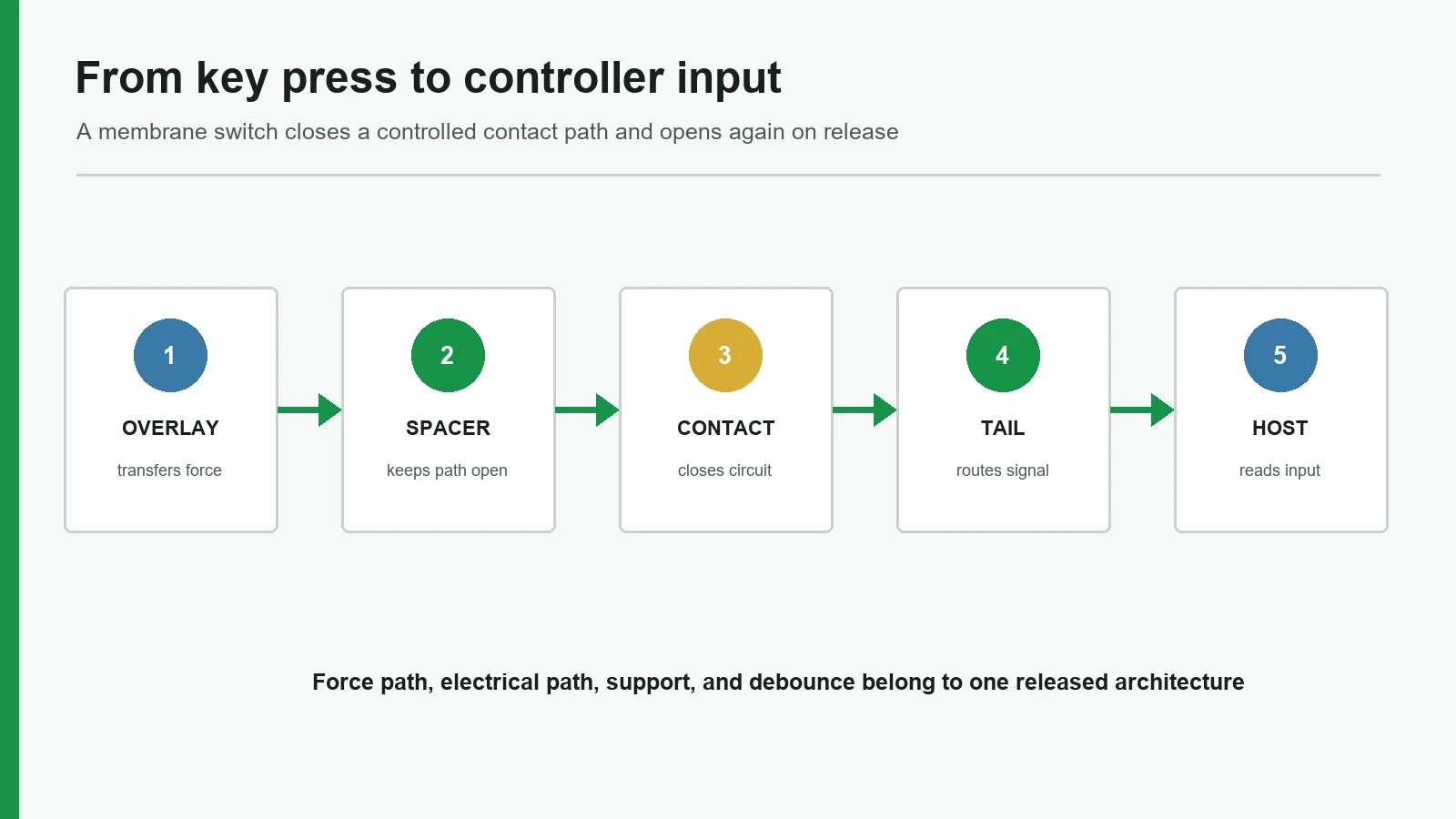
2. How Does a Membrane Switch Work — Actuation Sequence
How does a membrane switch work in physical order? The electrical idea is simple: complete a path that was held open by geometry. The engineering work is making that path repeatable after cleaning, vibration, temperature cycles, and assembly into a real housing.
2.1 Resting state (open path)
In the resting state, the polyester or polyimide spacer layer keeps upper and lower conductive areas apart. Insulation between isolated nets is typically specified in the high-megohm class on RFQs (commonly on the order of about 100 MΩ between nets in OEM guide language used by LID, Cubbison, and similar design-guide authors). No valid key press should produce a false closure from normal handling force outside the key zone, provided emboss height, key size, and enclosure support are correct.
2.2 Press through overlay and spacer
The operator presses a defined key area on the graphic overlay. The overlay is the wear and cleaning surface, not only decoration—second-surface (reverse) printing on PET or PC keeps legends under the film. Overlay thickness (often in the 0.15–0.25 mm film class on OEM faces), emboss (rim or pillow), and the stiffness of the ABS, aluminum, or sheet-metal housing behind the stack all change how much force reaches the contact zone. The upper film flexes into the spacer opening. If a stainless-steel metal dome (a selected OEM dome series) is present, the dome begins to collapse toward its snap point; if the build is non-tactile, the upper silver or carbon contact simply approaches the lower pad through the opening.
2.3 Contact closure
At the designed travel, conductive surfaces meet:
| Build | Closure mechanism | Operator cue |
|---|---|---|
| Tactile, metal dome | Dome snaps and bridges lower circuit pads | Distinct snap / click |
| Tactile, poly or formed dome | Polymer geometry collapses to contact | Softer snap, often quieter |
| Non-tactile | Flat or lightly formed upper contact meets lower pad | Little or no mechanical click |
Contact resistance on a new assembly is often written into RFQs as a low-tens-of-ohms target class (LID-class OEM literature frequently cites values under about 50 Ω when new, with a life limit under about 100 Ω after cycle testing). Those figures are common specification bands, not a universal guarantee for every DuPont or equivalent Ag paste system, Snaptron or Nicomatic-class dome series, and ISO 16750-style environmental profile.
2.4 Signal path to the controller boundary
Once closed, the path runs through printed Ag traces (matrix or discrete), any carbon overprint on silver pads, the flexible PET or FPC tail, and the connector into the host. Membrane switch operation ends, electrically, when the host MCU, ASIC, or PLC input sees a valid low-resistance path on the expected net. Firmware still has work: debounce timing, ghost-key prevention on diode-less matrices, LED strobing, and fault detection. Specifying only “the switch works on the bench” without ZIF/LIF pinout, contact side, 1.0 mm / 1.25 mm / 2.54 mm pitch class, and scan method is incomplete integration. TE Connectivity-style FPC attributes (pitch, actuator, contact side) are a useful checklist even when the connector brand differs.
2.5 Release and return
When the finger lifts, the stainless dome spring and/or PET elasticity open the gap again. Return force, residual denting of the PC overlay, acrylic adhesive squeeze-out into the key opening, and trapped air under a sealed dome can all spoil that reset. Venting through a planned spacer or carrier path is a known design control when trapped air changes tactile feel—Metal-dome engineering treats venting as application-specific geometry, not a single fixed channel recipe.
2.6 Sequence summary
| Step | What moves | Electrical state |
|---|---|---|
| 1 | Finger on printed key | Open |
| 2 | Overlay / upper layer flexes | Still open |
| 3 | Travel through spacer opening | Approaching threshold |
| 4 | Dome or contact meets lower circuit | Closed (intended key) |
| 5 | Current path on traces + tail | Host can detect closure |
| 6 | Release; dome/film restore gap | Open again |
That is the full answer to “how do membrane switches work” at the component level: geometry keeps the path open, a controlled flex closes it, the tail delivers the event, and the stack returns open without residual shorting.
3. Membrane Switch Technology Variants
Membrane switch technology branches mainly by feedback, circuit carrier, and lighting—not by a different physics of “pressure closes a gap.”
| Variant | Distinguishing feature | Typical use | Trade-off |
|---|---|---|---|
| Tactile (metal dome) | Stainless snap dome; crisp feedback | Industrial panels, medical instrument keys, equipment keypads | Dome selection and support critical; life is series- and load-dependent |
| Non-tactile | Closure without strong snap | Low-profile consumer-style faces, quiet rooms, simple overlays | Operators may over-press; rely on visual/audible product cues |
| Poly / embossed dome | Formed polymer feedback | Softer feel, flexible graphics | Less crisp than metal dome; forming limits apply |
| PET silver-ink flex circuit | Printed Ag traces on polyester | Most custom overlays | Current and density limits vs copper |
| FPC / PCB hybrid | Copper flex or rigid support under keys or connector | Dense LEDs, tighter pitch, tougher connector area | Higher cost and stack thickness |
| LED / backlit | Indicators, LGF, dead-front icons | Dark equipment, status keys | Opacity, registration, heat, and window tolerances add risk |
| Shielded stack | Foil, ITO, or printed shield layer | Noisy industrial environments | Grounding plan required; thickness and optics change |
3.1 Tactile vs non-tactile is a human-factors choice
Buyers sometimes treat “tactile” as automatically better. It is not. Choose tactile when operators wear EN 388-class gloves, work without looking at a Siemens or Rockwell-style HMI graphic, or need confirmation that a critical RUN/STOP command registered. Metal dome force for general keys is often discussed in LID and Nelson-Miller-class OEM guides around roughly 180–350 g (about 1.8–3.4 N), with 400 g+ bands for gloved industrial keys; always confirm the dome series drawing (diameter, trip force, click ratio) and sample feel on the production ABS or aluminum housing. Choose non-tactile when the product already provides clear LCD or buzzer feedback, when a flat consumer aesthetic dominates, or when hospital night-ward quiet operation matters more than snap.
For tactile construction families and options, see tactile membrane switches.
3.2 Circuit carrier changes reliability more than “brand of ink”
Silver ink on 0.125 mm-class PET covers a large share of custom membrane work because it is flexible and cost-effective for 5 V / low-mA signal switching into a GPIO or ADC. Carbon overprints on contact pads are a common reliability practice to reduce Ag migration and fretting wear (Nelson-Miller and Cubbison-class guides flag carbon as a contact finish option). When current, 0.5 mm-class fine pitch, repeated flex at a sharp bend under IPC-2223 flex guidance, or dense 0603 LED routing exceeds printed-silver comfort, 1 oz copper FPC (polyimide) or local FR4 PCB stiffening is the usual upgrade—not a thicker layer of the same ink.
3.3 Lighting does not change the closure law
Backlighting changes mask density, window alignment, light-guide placement, and sometimes circuit layer count. It does not replace the spacer gap or the need for a defined contact event. Dead-front icons that appear only when lit are a printing-opacity problem first and an LED placement problem second.
4. Electrical Operation, Specs, and Standards
Membrane switch operation is binary at the contact: open or closed on a designed net. Specification language must still be precise enough for a drawing package.
4.1 Common electrical targets (RFQ language, not universal guarantees)
| Parameter | Common RFQ framing | Notes |
|---|---|---|
| Contact resistance (new) | Low tens of ohms class (often < ~50 Ω in OEM guide language) | Depends on ink, dome, pad finish, contamination |
| Contact resistance (after life) | Higher allowed limit (often < ~100 Ω class in same literature) | Must name life method and cycle count |
| Insulation resistance | High-megohm class between isolated nets (often ~100 MΩ order) | Humidity and contamination matter |
| Switching voltage / current | Low-level signal class unless copper hybrid designed for more | Printed silver is not a power contactor |
| Actuation force | Dome series + overlay stack target (e.g. ~180–350 g general band) | Measure on final stack and housing |
| Travel | Typically sub-millimeter to low-millimeter class for membrane stacks | Emboss and spacer set feel |
| Life class | Multi-million actuations often marketed for metal domes | Application, force, and contamination limited |
Always attach the test method. ASTM F1578 is a standard family buyers commonly reference for membrane switch performance testing (actuation force, contact bounce, life, and related methods in the series); require the specific method numbers and acceptance limits on the FAIR / first-article plan rather than a vague “ASTM tested” line on a quotation PDF.
4.2 Standards and documentation buyers actually use
| Standard / framework | What it covers | What to request |
|---|---|---|
| IEC 60529 | IP Code for enclosure protection | Assembly-level test report for the mounted configuration—not a bare-switch slogan |
| ASTM F1578 family | Membrane switch performance test methods | Named methods, sample size, acceptance limits |
| IEC 61000-4-2 | ESD immunity test methods | Equipment-level plan; optional shield in the stack is only one input |
| RoHS (EU 2011/65/EU) | Restricted substances in electrical products | Material declarations for the BOM |
| REACH (EC 1907/2006) | SVHC communication duties | Supplier declarations as applicable |
| UL 94 | Polymer flammability classifications | Film/enclosure requests when the end product needs them—not automatic for every switch |
Quality laboratories and incoming inspection should map electrical and mechanical checks to a written plan. Use a written testing and quality plan whose methods and acceptance limits match the released drawing.
4.3 Controller boundary checklist
Before calling integration “done,” confirm:
- Matrix vs discrete wiring and ghost-key strategy
- Connector series, pitch, pinout, contact side, and stiffener thickness
- Maximum tail bend radius at the exit and at the connector
- Debounce time compatible with dome bounce
- LED common polarity and peak current if indicators share the tail
- Expected open/closed thresholds in the host ADC or digital input circuit
If those six items are undefined, the stack can be electrically perfect on a continuity meter and still fail in the product.
5. What Changes Feel and Signal Reliability
A sample that “clicks fine” on a desk can fail after lamination to a textured ABS housing or after a 90° tail fold behind a tight bezel. The usual drivers:
Overlay and emboss. Thicker PET (or hard-coated PC) and deep rim emboss raise actuation force and can mute a soft 180 g-class dome. Thin 0.15 mm-class overlays feel lively but show wear and UV ink damage sooner under IPA or quaternary cleaners.
Dome diameter, force, and support. Undersized FR4 or steel support under a 12 mm metal dome kills snap ratio. Soft PORON-class foam behind the lower circuit can absorb travel so the dome never fully collapses to the Ag pad.
Spacer thickness and opening registration. A spacer that is too thick increases travel and can make non-tactile keys feel dead. Misregistered openings create edge contact, intermittent shorts, or partial presses against the carbon overprint.
Adhesive squeeze and edge seal. 200MP-class acrylics such as 3M 467MP on metals, or 300LSE-class products such as 3M 9495LE on powder-coated and other low-surface-energy plastics, must match the substrate—wrong choice yields edge lift. Adhesive flow into the key cavity changes travel over time. Aggressive edge sealing without a vent plan can trap air under metal snap domes.
Tail mechanics. Sharp folds near printed silver traces create intermittent opens after a few hundred flex cycles. Wrong ZIF insertion depth or contact-side mismatch creates “dead rows” that look like STM32 or PLC firmware bugs.
Environment. Cleaning chemicals attack PC overlays faster than hard-coated PET grades in some chemistries; UV yellowing and abrasion are overlay problems first. Moisture paths usually start at tail exits, poorly bonded edges, or enclosure gaps—not at the silver pad itself.
EMI / ESD context. Industrial panels may need a copper foil, ITO, or printed carbon shield and a defined ground. That is an equipment-level design with IEC 61000-4-2 methods in the validation plan, not a sticker claim on the overlay.
6. When This Construction Is Not the Best Choice
Membrane stacks earn their place on sealed faces, sub-3 mm profiles, and custom graphics. They are the wrong default in these cases:
- High current or power switching — Printed Ag membrane contacts are signal devices (GPIO-level). Use relays, IEC 60947 power switches, or copper bus systems rated for the load.
- Deep travel and strong mechanical overtravel needs — Long-travel industrial joysticks, ISO 13850 emergency stops, or keys that must survive IK-rated impact abuse may need electromechanical or silicone elastomer solutions with different mechanics.
- Bare multi-touch gesture UIs — Projected-capacitive (PCAP) glass modules fit pinch/zoom and glove-optional consumer patterns better than a discrete 4×4 membrane matrix.
- IP claims without an enclosure program — If the project only needs a “waterproof sticker,” redesign the housing and silicone gasket strategy; do not expect a loose membrane to carry an IEC 60529 IP65/IP67 rating alone.
- Ultra-high cycle life under abrasive grit — Metal domes and PET faces have 1–5 million-class life in clean lab conditions; silica dust, sticky sucrose fluids, or unsealed grit change the failure mode. Validate with the real contaminant on the FAIR sample.
- Finished medical device approval by component alone — A membrane built under ISO 9001 is still a component. ISO 10993 biocompatibility, clinical validation, and FDA/MDR clearance apply to the finished device and its intended use, not to a keypad purchase order.
If two or more of those conditions apply, stop and compare alternative HMI constructions before tooling the overlay.
7. Where Membrane Switch Operation Shows Up
7.1 Industrial controls and instrumentation
PLC peripherals, gas analyzers, and CNC machine panels use membrane faces for sealed graphics and glove-friendly tactile keys under IEC 61000 industrial EMC expectations. Force bands trend toward 300–500 g for gloved presses; EMI shield layers and clear TE- or JST-class pinouts matter as much as Pantone artwork.
7.2 Medical and laboratory equipment (component scope)
Infusion pump UIs, diagnostic instruments, and ISO 13485-supply-chain lab devices often need IPA-cleanable PET overlays and defined tactile feedback. Treat the membrane as a component under the device manufacturer’s ISO 14971 risk file: cleaning chemistry, markings durability (second-surface print), and electrical safety belong in the device master record. Do not equate a supplier ISO 9001 process claim with FDA 510(k) or MDR finished-device approval.
7.3 Appliances and commercial equipment
Ovens, beverage dispensers, and fitness consoles use non-tactile or light-tactile membranes for flat styling and wipe-down faces. Heat near 60–80 °C zones, steam, and household cleaners drive Makrofol/Bayfol-class PC vs PET selection and 3M adhesive grade.
7.4 Transportation and specialty equipment
Cabin controls and portable field devices stress ISO 16750-style vibration/temperature profiles and tight tail routing behind dashboards. Hybrid polyimide FPC tails and 0.3 mm PET stiffeners are common when pure PET silver traces see repeated flex at the hinge.
7.5 Access control and kiosks
Public-facing door and payment keypads favor sealed graphics and hard-coated overlays. Non-tactile or UV-hardcoat faces appear where silent lobbies or flat styling is preferred; tactile metal-dome arrays remain common where users need confirmation without looking at a TFT display.
Across these uses, the operating principle does not change. The stack weights, force targets, and validation tests do.
8. Project Input Checklist and Next Step
Before asking any manufacturer—including JASPER as one available construction-review option—to interpret how a specific interface will work in your housing, collect:
| Input | Why it matters to operation |
|---|---|
| Overlay artwork + key map | Defines press zones and legend wear surfaces |
| Layer stack sketch (even rough) | Shows dome, spacer, shield, LED assumptions |
| Tactile vs non-tactile target + force band | Sets dome or flat-contact path |
| Circuit type (Ag PET / FPC / PCB) + matrix map | Sets resistance and routing limits |
| Connector series, pitch, pinout, contact side | Defines controller boundary |
| Tail exit, length, bend constraints | Prevents intermittent opens |
| Enclosure material, flatness, land area | Controls support and feel |
| Environment: chemicals, IP goal, UV, temperature | Drives film, adhesive, gasket plan |
| Electrical limits: voltage/current, ESD plan | Avoids overloading printed contacts |
| Sample tests: force, life method, insulation, continuity | Ties claims to ASTM F1578-class methods or agreed lab plans |
| Acceptance criteria for first article on real housing | Bench continuity alone is not enough |
Review the interface construction for the application—stack, contact type, tail, and host boundary—against the real enclosure and environment. Start from the membrane switches hub for construction families, use tactile membrane switches when snap feedback is required, and align inspection language with testing and quality. For drawing-level decisions beyond pure operating principle, continue with the site membrane switch design guide.
9. Frequently Asked Questions
How do membrane switches work in one sentence?
Pressure on a defined key area flexes a contact layer or metal dome through a spacer opening onto a lower circuit, closing a path that the flexible tail and connector deliver to host electronics until release opens the gap again.
How does a membrane switch work without a mechanical lever?
Geometry replaces the lever. A spacer sets an open gap; film flex and optional dome snap provide the motion; printed conductors provide the electrical bridge. No individual plastic key housing is required for each position.
What is the difference between tactile and non-tactile membrane switch operation?
Both close an electrical path. Tactile builds add a snap dome or formed feature so the operator feels confirmation. Non-tactile builds close with little mechanical click and depend more on product UI feedback.
How long does a membrane switch last?
Life depends on dome series, force, contamination, travel, and test method. Metal dome products are often marketed in the 1–5 million actuation class in Snaptron-class and OEM vendor literature; treat that as a lab class to validate under ASTM F1578-family methods, not a blanket 10-year field guarantee.
Can a membrane switch be waterproof?
The closure principle stays the same. Water resistance requires overlay continuity, adhesive and edge design, tail exit control, and—critically—an enclosure strategy evaluated under IEC 60529 for the mounted assembly. A bare panel slogan is not an IP rating.
How does the switch connect to a controller?
Most designs use a flexible tail into a ZIF/LIF, crimp housing, pin header, solder pads, or a stiffener-backed connector area. Pitch, pinout, contact side, and bend radius must match the host drawing.
Why does key feel change between samples?
Dome force, overlay thickness, spacer height, emboss, adhesive stack, support foam, and housing flatness all shift actuation. Compare samples on the production-intent enclosure, not only on a flat bench plate.
Is membrane switch technology suitable for medical devices?
As a cleanable, low-profile component technology, yes it is widely used on medical equipment interfaces. Finished-device validation, risk management, and regulatory approval remain the device manufacturer’s responsibility and are separate from component fabrication.
What should be tested before production approval?
Continuity and insulation to drawing limits, actuation force and feel on the real housing, tail/connector insertion cycles, environmental checks required by the application, and any ASTM F1578-family or agreed methods listed on the sample plan. Record failures to layer cause, not only to “bad switch.”
Technical References
- Source: ASTM F1578 membrane switch contact closure cycling practice. Accessed 2026.
- Source: IEC 60529 enclosure protection classification. Accessed 2026.
- Source: IEC 61000-4-2 electrostatic discharge immunity testing. Accessed 2026.
- Source: 3M membrane switch construction and spacer technical data. Accessed 2026.
- Source: Covestro Makrofol and Bayfol Film Selector Guide. Accessed 2026.
- Source: Snaptron metal dome venting guidance. Accessed 2026.
- Source: TE Connectivity FPC connector product drawings. Accessed 2026.
- Source: IEC 60068-2-14 temperature change testing. Accessed 2026.
- Source: IPC-6013 qualification and performance specification for flexible circuits. Accessed 2026.
- Source: RoHS Directive 2011/65/EU restricted substances scope. Accessed 2026.
- Source: REACH Regulation EC 1907/2006 chemical substance framework. Accessed 2026.
- Source: ISO 9241-210 human-centred design for interactive systems. Accessed 2026.
Match the switch architecture to the controller
Send the key map, tactile preference, circuit logic, tail and connector details, enclosure support, and installed test states.