
Seat position
ControlName front passenger, rear position, bus seat, commercial seat, or project module and its geometry.
Failure modeOne generic mat is assumed to cover seats with different load paths.
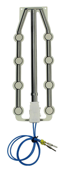
SBR means Seat Belt Reminder or Safety Belt Reminder. The occupancy component answers whether the seating position meets a project-defined occupied condition. A buckle switch or another customer input answers whether the belt is fastened.
JASPER can design and manufacture the pressure, contact, or confirmed resistance-responsive mat inside the seat. The OEM or Tier 1 combines inputs, applies timing and warning logic, validates the complete system, and owns regulatory or assessment documentation.
This distinction prevents a component quotation from implying control over the warning lamp, chime, ECU, buckle switch, occupant classification, or vehicle behavior.
The seat component should be released without pretending it owns the complete system.
Name front passenger, rear position, bus seat, commercial seat, or project module and its geometry.
Failure modeOne generic mat is assumed to cover seats with different load paths.
Define the seat-level state the sensor should represent and the fixture used to reproduce it.
Failure modeThe supplier and ECU teams use different meanings for occupied.
Document preload, trim tension, common objects, edge loads, and non-occupant conditions.
Failure modeThe reminder input activates when the seat should remain empty.
Separate occupancy signal, buckle status, connector ownership, timing, diagnostics, and customer logic.
Failure modeA sensor component is incorrectly treated as the complete SBR system.
Release tail, wire, connector, pinout, restraint, harness route, and seat movement boundary.
Failure modeThe signal is lost through cable strain or interface mismatch.
Assign component, installed seat, ECU, warning behavior, vehicle, and regulatory evidence.
Failure modeA component sample is used as proof of vehicle-level performance.
The sensor drawing, interface control document, and validation plan should show who owns each decision.
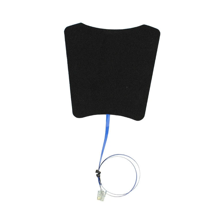
The occupancy component describes the seat condition. The buckle switch describes latch status. The customer controller decides when and how a reminder appears after applying its own diagnostics, timing, filtering, and validation.
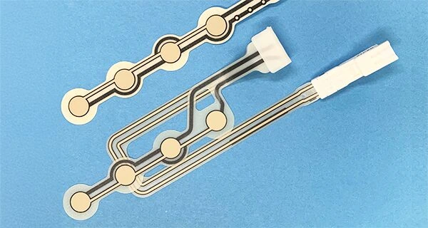
A rear bench, contoured passenger seat, and repeated bus seat can place the occupant load and harness exit in different areas. Review each seat position before reusing one mat geometry.
Review cushion section, foam behavior, upholstery tension, support, sensing zone, and installation boundary.
Release sensing principle, signal expectation, tail direction, cable protection, connector, and test access.
Check fit, false activation, occupied response, cable strain, connector fit, and repeatability in the real seat.
Lock drawing, material stack, circuit, connector, inspection, packaging, retained sample, and revalidation triggers.
Check trim preload, object cases, active-zone size, seat position, occupancy threshold, and customer logic.
Review load coverage, sensor output, buckle status, connector, harness, ECU input, and validation condition.
Inspect tail strain, connector seating, cushion movement, zone placement, contact behavior, and filtering boundary.
Compare cushion geometry, foam, trim, installation, sensor revision, buckle interface, and software configuration.
The customer system remains responsible for final reminder behavior.
Custom occupied-seat input for a defined front passenger cushion and harness.
Seat-position-specific mats for bench, split, folding, or modular rear seating.
Repeated commercial seat modules with consistent installation and protected lead routing.
Custom pressure or contact mats for passenger seating modules and fleet installation.
Non-standard cushions requiring a custom active zone, connector, and validation method.
SBR sensor usually means a Seat Belt Reminder or Safety Belt Reminder input. On this page it refers to the seat occupancy component, not the complete vehicle warning system.
Only if the seat geometry, load path, installation, routing, signal, and validation evidence support reuse. Different positions often need different zones and cable exits.
This product page covers the custom seat sensor component. ECU logic, diagnostics, calibration, warning behavior, vehicle integration, and compliance remain customer responsibilities.
Send the seat drawing, seating position, occupied and empty cases, signal expectation, buckle boundary, tail route, connector, sample quantity, and validation plan.
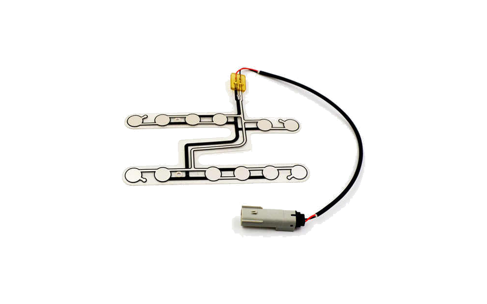
Compare the complete custom seat occupancy and pressure sensor family.
Review Resource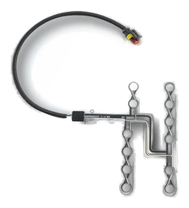
Review the physical mat, zone, installation, and cable-routing decisions.
Review Resource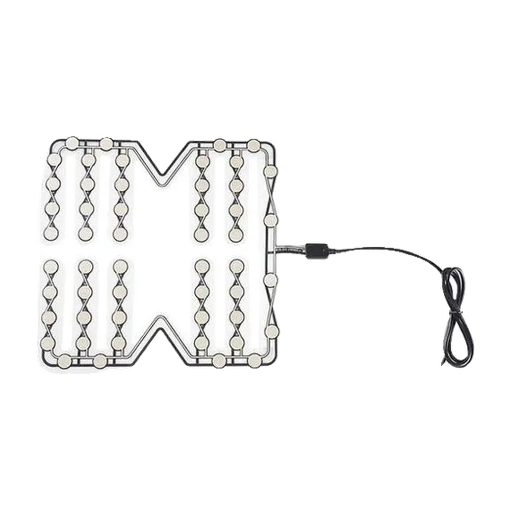
Review repeated commercial seat modules and protected routing.
Review ResourceJASPER can review the occupancy component, cushion boundary, sensing zone, interconnect, seat-level evidence, and production controls while your system team owns reminder logic and vehicle validation.
Share the project basics. JASPER will review the stack, materials, connector, quantity, and production risks.