Dongguan, Guangdong 523927, China[email protected]+86 136 3262 5290
Home / Products / Car Seat Occupancy Sensor / Bus Seat Occupancy Sensor
COMMERCIAL PASSENGER SEAT SENSOR COMPONENTS

Bus Seat Occupancy Sensor

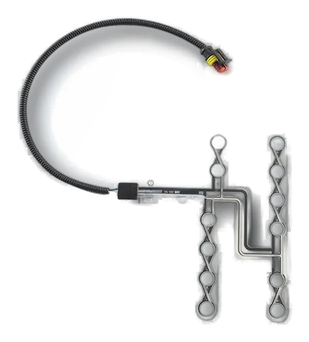
A bus seat occupancy sensor is a thin pressure or contact-responsive component shaped for a commercial passenger cushion. The design must repeat across seat modules while protecting the active area, lead, connector, and installation position through service and cleaning.
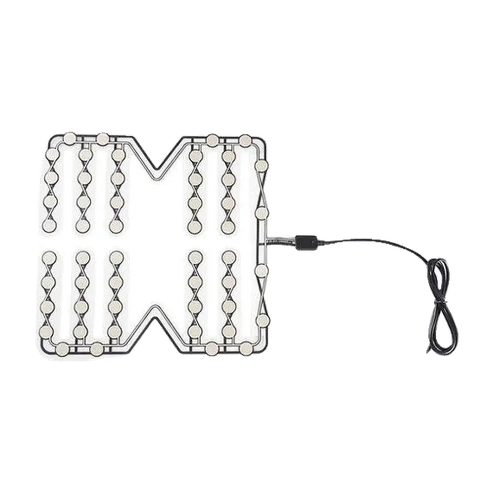
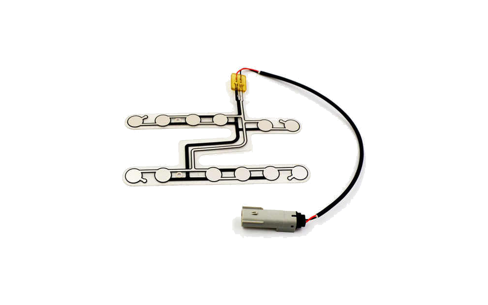
Custom bus seat occupancy sensor mat for a commercial passenger cushion
Module repeatedseat width, cushion revision, orientation, install datum, and sensor part control
Lead protectedframe edges, brackets, hinges, cleaning, service, and passenger use
Scope definedcomponent signal separate from fleet software, telematics, buckle logic, and vehicle approval

Commercial Seat Sensors Must Repeat across Real Seat Modules

A bus seat occupancy sensor is installed within a bus, school bus, taxi, shuttle, or other commercial passenger seat to provide a project-defined seat-state input.

The same route can support customer-owned seat belt reminder, seat-status, or monitoring architectures. JASPER supplies the custom sensor component and interconnect, not fleet analytics, telematics, warning software, or the complete vehicle system.

Commercial programs benefit from a controlled seat-module drawing, installation method, connector position, sample approval record, packaging plan, and traceability between repeated seat builds.

Bus Seat Occupancy Sensor projects fit when:

  • a standard sensor does not match the commercial seat cushion or harness
  • multiple seat modules need a controlled installation and part reference
  • the cable route can be protected from frame, passenger, cleaning, and service loads
  • the customer owns final reminder, monitoring, telematics, and vehicle validation

Six Controls Keep Repeated Commercial Seats Consistent

Volume alone does not make one seat module identical to the next.

01

Seat module identity

Control

Release cushion width, revision, orientation, supplier, install datum, and applicable seat positions.

Failure mode

The sensor is installed in an unreviewed seat variant.

02

Occupied zone

Control

Map passenger posture, cushion load, bolsters, seams, support, and off-center use.

Failure mode

A narrow active area produces inconsistent passenger detection.

03

Installation method

Control

Define layer, orientation, retention, adhesive, foam groove, trim step, work instruction, and inspection.

Failure mode

Operators position the mat differently across repeated modules.

04

Cable protection

Control

Route the tail and lead away from frame edges, brackets, hinges, floor mounts, cleaning tools, and service access.

Failure mode

The component passes sampling but is damaged during operation or maintenance.

05

Connector interface

Control

Control connector, pinout, mating part, restraint, branch location, labeling, and replacement boundary.

Failure mode

Seat harness variants create wrong or loose connections.

06

Production evidence

Control

Approve component test, installed-seat sample, work instruction, packaging, lot traceability, and change triggers.

Failure mode

A sample becomes the only undocumented installation standard.

Specify the Sensor as Part of a Repeatable Seat Module

The production package should control both the component and how it is installed.
DecisionOptions to ReviewRelease Question
Vehicle and seat typeCity bus, school bus, coach, shuttle, taxi, work vehicle, or project moduleWhich cushion revision and seat positions use this sensor?
Sensor layoutSingle zone, multiple zones, contour mat, compact pad, linked zones, or custom outlineHow does the active area cover passenger load without frame interference?
InstallationUnder foam, inside cushion, below trim, above support, adhesive, pocket, or local restraintHow will every assembly operator reproduce the approved position?
Electrical inputContact state, pressure-related response, confirmed FSR-type behavior, or customer-defined signalWhat component behavior reaches the customer controller?
Lead and connectorSide or rear exit, wire length, strain relief, branch, named connector, and service disconnectHow is the interconnect protected through operation, cleaning, and service?
Production controlDrawing, work instruction, sample master, inspection, label, packaging, traceability, and revalidationWhich records keep repeated seats equivalent after changes?
Bus seat occupancy sensor mat designed for repeated commercial seat installation
REPEATED INSTALLATION

Control the Seat Work Instruction as Carefully as the Sensor Drawing

A custom mat can still vary if installers rotate it, shift the active area, pull the lead, trap it at a foam edge, or route the connector differently across modules.
  • use physical datums, orientation marks, and a clear installation photo
  • inspect active-zone location and cable route at the seat line
  • retain an approved seat module, not only a loose sensor
  • revalidate when the cushion, trim, frame, or harness changes
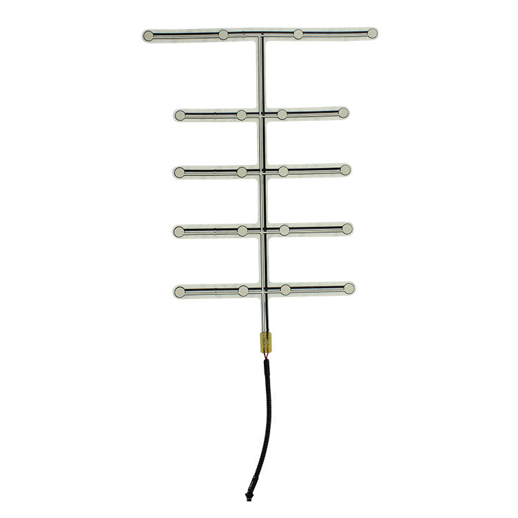
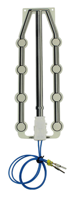
Seat occupancy and SBR sensor leads with connector options for service routing
SERVICE AND CLEANING

Protect the Lead beyond the First Assembly

Commercial passenger seats see repeated use, cleaning, trim removal, service access, cushion replacement, and contact with frame hardware. Route and restrain the interconnect for that real service boundary.

  • keep conductors away from sharp metal, hinges, and moving brackets
  • define connector access without pulling the sensor body
  • name cleaning and moisture exposures instead of assuming an IP rating
  • include service reinstallation in the project validation plan

Release the commercial seat sensor Against the Real Seat

01

Define the seat state

Name the seating position, occupied and empty conditions, intended system input, and customer-owned logic.

02

Map the load path

Review cushion section, foam behavior, upholstery tension, support, sensing zone, and installation boundary.

03

Close circuit and routing

Release sensing principle, signal expectation, tail direction, cable protection, connector, and test access.

04

Approve seat-level samples

Check fit, false activation, occupied response, cable strain, connector fit, and repeatability in the real seat.

05

Control production changes

Lock drawing, material stack, circuit, connector, inspection, packaging, retained sample, and revalidation triggers.

Diagnose the Repeated Seat Module, Not Only the Loose Sensor

01

Some seats miss passengers

Compare module revision, active-zone placement, foam, trim, installer method, sensor lot, connector, and customer logic.

02

False occupied seats

Check preload, cleaning or service pressure, object cases, support points, installation shift, and active-zone size.

03

Cable damage in service

Inspect frame edges, brackets, restraint, connector access, trim removal, seat movement, and replacement work.

04

Mixed fleet behavior

Review vehicle and seat variants, sensor revisions, harness branches, controller inputs, installation records, and calibration ownership.

Commercial Passenger Seat Applications

The sensor component can support several customer-owned architectures.

01

City bus seats

Custom occupied-seat inputs for repeated passenger seat modules.

02

School bus seats

Pressure or contact mats shaped for defined school-bus cushions and routing.

03

Coach and shuttle seats

Seat-specific sensing zones, leads, connectors, and service boundaries.

04

Taxi passenger seats

Compact or shaped sensors for front or rear commercial passenger seating.

05

Work and specialty vehicles

Custom modules for passenger or operator seat-state input.

06

Fleet seat belt reminder

Occupancy components used with customer-owned buckle, warning, and vehicle logic.

Send One Seat Module and the Repetition Plan

A commercial program needs both a working sensor and a repeatable installation package.

  • vehicle and seat type, cushion revision, orientation, drawing, photo, or sample
  • seat positions, passenger load zone, object cases, and expected input behavior
  • installation layer, datum, retention, work instruction, and inspection point
  • tail exit, lead route, frame risks, connector, pinout, restraint, and service access
  • cleaning, moisture, repeated use, seat movement, cushion replacement, and conditioning
  • sample quantity, pilot build, annual estimate, packaging, traceability, and change control
Send Seat Sensor Project Files

Bus Seat Occupancy Sensor FAQ

What is a bus seat occupancy sensor?

It is a pressure, contact, or confirmed resistance-responsive component installed within a bus or commercial passenger seat to provide a customer-defined occupied-seat input.

Can the same sensor be used across many bus seats?

Yes when the seat modules, installation, load path, connector, and validation support reuse. Variants should be reviewed and controlled by drawing.

Can it support seat belt reminder systems?

It can provide an occupied-seat input. Buckle status, warning behavior, controller logic, calibration, diagnostics, and vehicle validation remain customer responsibilities.

How is the cable protected?

The project should define tail exit, lead routing, reinforcement, restraint, connector mounting, frame clearance, service access, and repeated installation checks.

What should be approved before volume production?

Approve the component, installed seat module, work instruction, cable route, connector, occupied and empty cases, packaging, traceability, and revalidation triggers.
Related Seat Sensor Resources

Release the sensor and the commercial seat work instruction together.

JASPER can review the repeated seat module, active zone, sensor structure, protected interconnect, component evidence, packaging, and production controls.

Start Seat Sensor ReviewContact Engineering