
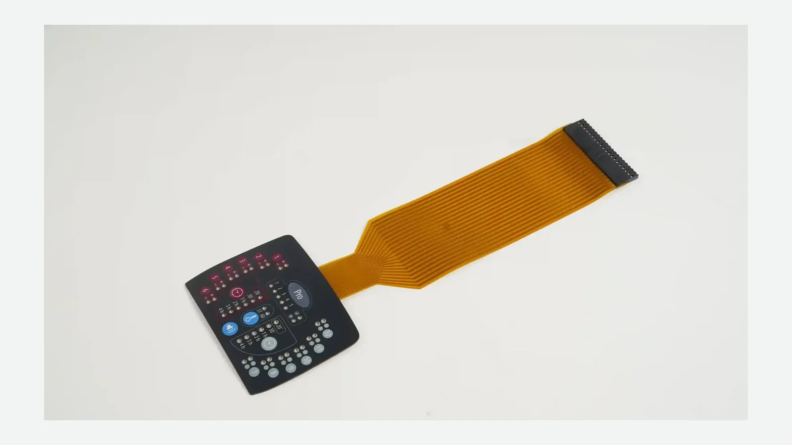
A membrane switch connector is not a single plastic housing on a catalog page. It is the full interconnect system—flexible tail, contact pitch, contact side, stiffener, pinout, exit route, bend and strain relief, and the mating part on the board—that must be locked together before sampling. Choose those items as one package, then prove them on the installed path, not only on a flat bench panel.
1. Why connector and tail choices fail late
A switch can pass flat continuity and still fail after the first real fold into a housing. The open circuit, intermittent key, reverse contact side, or assembly rework often starts at the membrane switch connector interface, not under the key graphic. Termination is a controlled part of the product architecture. Field failures still cluster where the enclosure forces a crease the drawing never showed.
What freezes early is easy to underestimate. Tail exit and length shape circuit routing and adhesive outline. Pitch and pin count fix the mating footprint on the host PCB. Contact side and stiffener thickness lock insertion into the ZIF or FFC actuator. Pinout ownership ties the key matrix to the controller firmware. Late “small” edits can force artwork, spacer dies, and inspection fixtures to move with the interconnect.
| Failure chain stage | What gets locked early | What fails later if the decision stayed open |
|---|---|---|
| Mating connector ownership | Board footprint, actuator style, cable acceptance | Sample will not insert; second RFQ under same part number |
| Pitch and positions | Tail width, contact artwork | Wrong connector family, re-spin of circuit |
| Contact side / orientation | Stiffener face, insertion direction | Electrical open with “correct” pin count |
| Stiffener / stack thickness | ZIF insertion feel and contact planarity | Buckled tail, partial contact, damaged actuator |
| Exit and length | Circuit gather, adhesive cut | Forced twist, short reach, sealed-path conflict |
| Bend and strain relief | Fold path in enclosure | Trace crack after install or service |
| Pinout ownership | Test fixture and firmware map | Keys swapped, LEDs on wrong pins |
| Assembly sequence | Access windows, order of operations | Connector reachable only before a cover that never reopens |
| Decision closed before sample? | Typical locked assets | Safe to build production-intent tails? |
|---|---|---|
| Yes — connector drawing, route, pinout, stiffener closed | Tail outline, contact end, pin map | Yes, against named revision |
| Partial — pitch known, exit still open | Circuit may look finished | No — hold multi-tool release |
| No — “use a ZIF” only | Front artwork only | No — RFQ invents interconnects |
The rest of this article turns that risk into nine closed decisions, a step sequence from board connector to installed-path check, and a package list to share for review.
2. Nine criteria for choosing a membrane switch connector system
Treat each item as a release criterion. A is evidence the package can proceed. A is a reason to hold sampling even if the front graphic is approved.
2.1 Mating connector ownership
Name the board-side part. A membrane switch connector decision that stops at “ZIF style” is not owned. Connector manufacturer drawings control pitch, contact mating location, orientation, actuator style, and accepted flex construction. TE Connectivity product 1-2013496-0, for example, lists centerline pitch 0.3 mm (0.012 in), bottom contact mating location, right-angle PCB mount, and a back flip-lock FPC actuator—fields that must match the tail end design rather than a verbal description. The selected project drawing remains controlling even when that example part is obsolete or replaced.
Manufacturer, series or part number, revision, datasheet or drawing, and who owns the footprint on the host PCB.
“Any 1.0 mm ZIF” with no part number, no accepted thickness, and no contact-side callout.
2.2 Pitch and contact count
Pitch is center-to-center spacing of contacts; contact count is how many conductors the membrane switch tail carries, including commons, grounds, LEDs, and shield returns. Board connectors are available in several pitch families, but the selected mating-connector drawing sets the legal pitch for the project.
Pitch and position count match the named connector; width and insertion length are dimensioned from that drawing.
Pitch chosen from a previous product while the new board uses a different footprint.
2.3 Contact side, orientation, and actuator style
Contact side decides which face of the tail faces the connector contacts. Orientation and actuator style (for example back flip-lock versus other FPC actuator types on TE-class drawings) decide how the operator inserts and locks the flex. Reverse the contact side and the assembly can look seated while remaining open.
Drawing notes contact face, insertion direction, polarizing features if any, and actuator open/closed states for inspection.
Pin count only—no face, no direction, no photo or section of the mated stack.
2.4 Stiffener and accepted flex stack thickness
For bare-tail ZIF/FFC mating, a stiffener under the contact end makes the membrane switch tail rigid enough to insert and keep contacts planar. Thickness, length of stiffener, and total stack must fall inside the connector’s accepted cable/flex window. Too soft and the end buckles; too thick and the actuator will not close or contacts will not wipe correctly.
Stiffener material and thickness tied to the connector drawing; contact finish called out for wear against the connector.
“Add a stiffener” without thickness, length past the contacts, or acceptance check on a sample connector of the production part.
2.5 Membrane switch tail exit, length, and width
Exit edge and station along that edge set how the circuit gathers and whether the adhesive outline stays clear of the fold. Length must follow the real enclosure path—screw bosses, ribs, gasket lands, display windows—not the shortest line on a flat PDF. Width must carry the pitch and count without crowding print or copper rules.
Exit marked on the panel outline; developed length shown with intermediate bend points; clearance to sealed borders documented.
Tail length taken as panel-to-PCB air distance with no section through the housing.
2.6 Flexible tail bend radius and strain relief
Flexible tail bend radius is not a single catalog millimeter for every stack. Printed silver on PET and copper FPC tolerate different fold severity; sharp folds at the panel exit or at the stiffener step are common open-circuit sites. Strain relief—anchoring, supported fold, or controlled service loop—spreads load so a tug or repeated service does not crack traces.
Bend path drawn in the enclosure; minimum fold intent stated as “no crease at exit / support at stiffener transition”; sample fold test required before approval.
90° fold hard against a sharp plastic edge with no relief and no installed-path continuity check.
2.7 Printed silver tail versus copper FPC path
Printed silver or carbon on PET with a bare stiffener tail into a board ZIF remains a frequent industrial keypad build. A copper FPC path—or a denser membrane switch FPC connector arrangement—earns its place when track density, current, length, or shielding needs exceed what the printed silver layout can carry cleanly for that design. PCB-supported constructions and PCB/FPC HMI assemblies change connector placement, height, and test access.
Circuit technology chosen against matrix density, LED/backlight current, length, and EMC needs; connector family matches that stack.
Copper FPC ordered “for quality” when a low-count silver ZIF already mates the board and service needs favor a reopenable bare tail.
2.8 Pinout ownership and signal map
Pin 1 must mean the same thing to the switch artwork, the test fixture, and the firmware. Freeze pinout only after connector, contact side, accepted flex thickness, and routing envelope have been reviewed together. Early pin flexibility can help routing; silent late swaps create interface errors that look like “bad switches.”
Controlled pin map with revision, owner, and LED/common/shield lines identified.
Matrix drawn on the overlay only; connector end numbered two different ways in email threads.
2.9 Mating access, assembly sequence, and installed-path test
If the connector is reachable only before a cover that never reopens, service strategy is already chosen. Assembly sequence must state when the tail is folded, when the actuator is closed, and who verifies seating. Continuity on a flat sample is necessary and not sufficient. Quality testing plans should include folded and installed conditions when the product will live in those states.
Written sequence, access photos or sections, and a test matrix that includes post-fold checks.
Bench-only pass criteria for a tail that will be creased into a tight housing on the line.
3. Termination options: choose by the receiving interface
Use this table as a decision aid, not a ranking of “best connector.” The receiving interface and service model decide.
| Option | When it fits | What must be locked | When it is not the best choice |
|---|---|---|---|
| Bare membrane switch tail into board ZIF/FFC | Board already has a flat-flex connector; low profile preferred; service may reopen the joint | Pitch, positions, contact side, stiffener, insertion length | Board has only pin header or harness; no ZIF footprint |
| Female/male header housing on tail | Board or panel uses posted headers; polarised plug preferred | 0.100 in (or named) pitch family, housing orientation, latch if used | Height or footprint will not fit; board is pure ZIF |
| Crimp housing on tail | Harness run to remote controller; field cable swap needed | Crimp system, plating, housing series, strain relief | No room for housing; board expects bare flex only |
| Solder tabs / direct solder | Permanent joint accepted; process control exists | Heat exposure, pad design, rework policy | Frequent service disconnect required |
| Hot-bar / bonded copper flex | Dense copper flex to pads; controlled process available | Bar temperature, dwell, force, pad geometry | Hand assembly without process window |
| PCB/FPC support at connector | Connector needs rigidity, denser routing, or defined mounting | Board thickness, mounting, test access | Simple low-count silver ZIF already meets all needs |
Industrial membrane interconnect families are also marketed at 2.54 mm pitch for membrane integration—Amphenol Communications Solutions Clincher application content is one public example of that positioning. Treat any series as drawing-controlled; do not import life, current, or IP65/IP67/IP68 numbers from marketing pages into the switch drawing without the project’s own validation under the assembled enclosure.
Text route (typical bare-tail path — project geometry differs):
Graphic / key area
circuit gather toward exit edge
membrane switch tail leaves panel (exit station marked)
free flex length through enclosure path
bend zone (supported; no sharp crease)
strain-relief anchor or service loop (if required)
stiffener start
contact pad area (pitch, count, contact side)
insert into named board connector (actuator open → close)
installed-path continuity / functional check
4. Step-by-step specification process
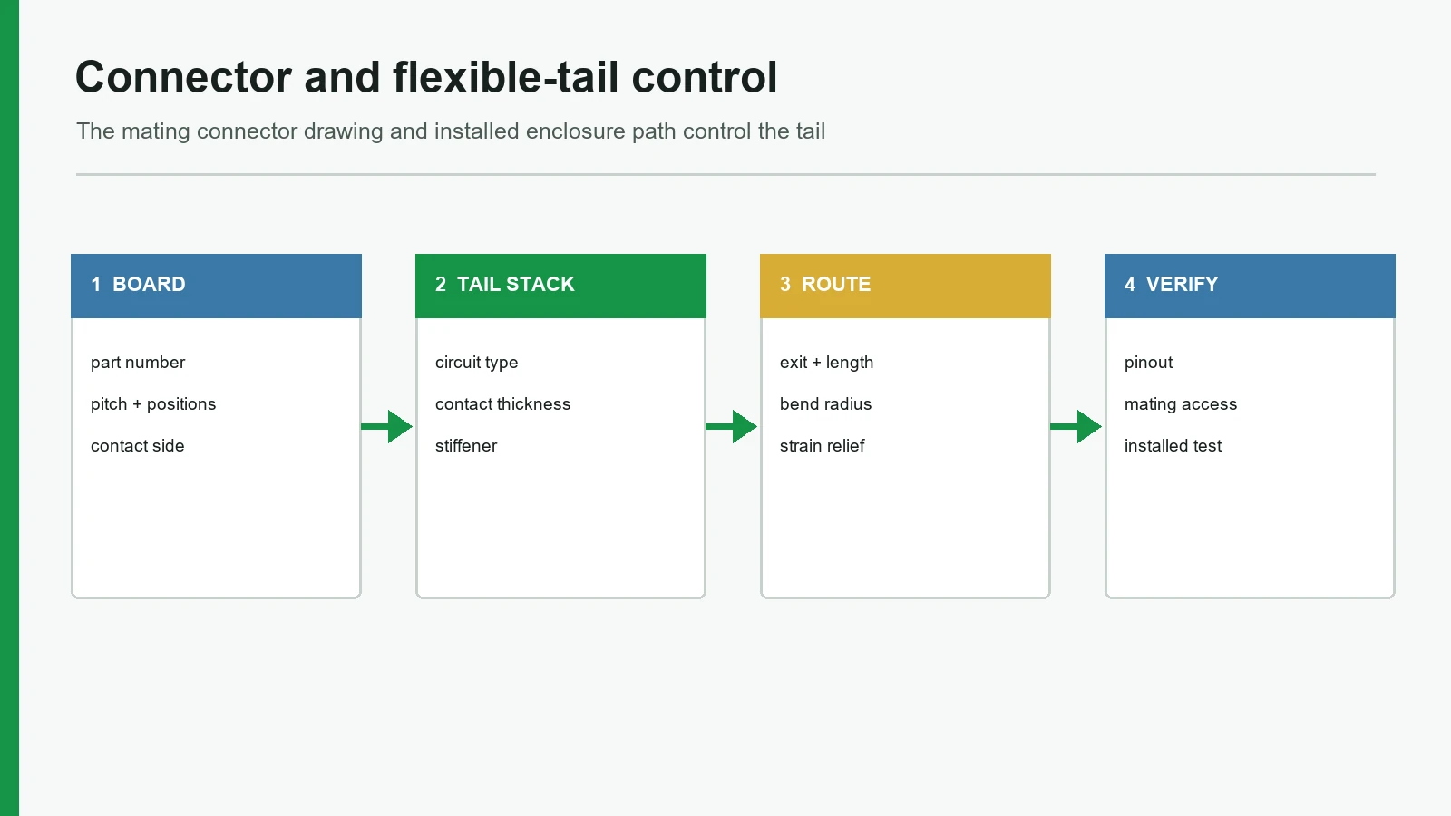
Step 1 — Capture the board connector before redrawing the tail
Collect the manufacturer drawing or datasheet for the mating part. Record pitch, positions, contact mating location, orientation, actuator style, and accepted flex thickness. If the board is not frozen, list the candidate footprints and the mechanical envelope.
Step 2 — Map the enclosure route
From panel attach face to connector location, mark bosses, ribs, gasket lands, displays, and service covers. Choose exit edge and developed length against that path. Note where a flexible tail bend radius will be forced if the route is wrong.
Step 3 — Select termination class from the receiving interface
Use the decision table in §3. Prefer the lowest-height, fewest-process option that still meets service and vibration needs. Do not add a housing on the switch “for reliability” if the board already provides a correct ZIF and height is critical.
Step 4 — Close stiffener, contact face, and pinout together
Dimension the contact end from the connector drawing. Assign pin 1 ownership. Include LED, common, and shield lines in the count. Align test fixture numbering with firmware.
Step 5 — Issue the interconnect package with the RFQ or sample request
Send more than front artwork. Minimum useful set:
- Connector manufacturer, part number, revision, and drawing
- Pitch, positions, contact side, insertion direction
- Tail exit, length, width, and fold path in the enclosure
- Stiffener construction and thickness intent
- Pinout map with owner and revision
- Circuit technology (printed silver vs copper FPC) and any shield
- Assembly sequence and service access notes
- Acceptance tests for flat and installed conditions
Step 6 — Build a production-intent interconnect sample
Sample materials at the contact end should match production intent or be declared as substitutes. Fit the real connector part when possible—not a look-alike.
Step 7 — Run flat and installed-path checks before approval
| Check | Flat bench | Folded / installed |
|---|---|---|
| Continuity / opens | Required | Required after representative fold |
| Contact seating / actuator state | Visual on sample connector | Visual after final assembly sequence |
| Pin map vs key matrix | Fixture or manual map | Spot-check critical keys after install |
| Strain at exit and stiffener step | Optional | Required if product sees service or vibration |
| Seal path near tail exit | N/A on loose switch | Only with defined enclosure test article (IEC 60529 framing) |
Hold golden-sample approval until the installed path passes the checks that match how the product is built.
5. Release blockers that should stop sampling
These override a low unit price and a finished front graphic:
- No mating connector part number or drawing — “ZIF” is not a specification.
- Pitch or pin count taken from a different product without board confirmation.
- Contact side and insertion direction missing from the drawing.
- Stiffener undefined for a bare-tail design.
- Tail length is air distance, not enclosure path length.
- Sharp fold against a hard edge with no strain relief concept.
- Pinout frozen in firmware before connector and route review.
- Bench continuity only for a tail that will be folded in production.
- IP rating on the loose switch because the tail “looks sealed” (conflicts with IEC 60529 enclosure framing).
- Copper FPC ordered without density/current/EMC driver when a simple silver ZIF already matches the board.
If two or more of these remain open, hold production-intent tail tooling and connector-end materials until the package is closed.
6. Drawing checklist for membrane switch connector and tail packages
Use this list as a gate before sample approval:
- Mating connector manufacturer, part number, and revision are named.
- Pitch, position count, and tail width match that drawing.
- Contact side, insertion direction, and actuator style are noted.
- Stiffener material, thickness, and length relative to contacts are defined.
- Membrane switch tail exit edge and station are dimensioned on the panel.
- Developed length includes the real enclosure path and service loop if any.
- Flexible tail bend radius intent and strain-relief method are shown or described.
- Circuit technology (printed silver/carbon vs copper FPC) is stated with reason.
- Pinout map has a single owner and revision; LED/common/shield lines included.
- Assembly sequence and mating access are documented.
- Flat and installed-path electrical checks are listed with pass criteria.
- Any sealing claim near the exit is tied to a defined enclosure test article.
7. Frequently asked questions
What is a membrane switch connector in practical terms?
It is the interconnect system that joins the keypad circuit to the host electronics: the flexible tail, contact geometry, stiffener when used, pinout, and the mating connector or termination method on the board or harness. Specifying only a housing name leaves the system incomplete.
What is the most common membrane switch connector approach?
Bare stiffened tails into board-mounted ZIF or FFC-style connectors are common when the PCB already carries that footprint. The most common option is still wrong if the board uses headers or a harness only. Match the receiving interface first.
What details must a membrane switch tail drawing include?
Exit location, developed length, width, pitch, position count, contact side, stiffener, bend and strain-relief intent, pinout, and reference to the mating connector drawing. Length must reflect the enclosure path, not only panel-to-board clearance on a flat view.
Why does flexible tail bend radius matter?
Sharp folds concentrate stress in printed or etched conductors. Damage often appears after install or after a few service cycles, not on the first flat continuity test. Design a supported path and verify continuity after a representative fold.
What is a tail stiffener?
A stiffener is a reinforced section at the contact end of a flexible tail. It helps the tail insert into a ZIF/FFC connector and keeps contacts planar. Thickness and length must match the connector’s accepted flex stack.
When should teams use a copper FPC tail or membrane switch FPC connector path?
When track density, current, length, shielding, or support needs exceed what a printed silver PET tail can implement cleanly for that product. It is not automatically higher quality for every low-count industrial keypad.
Can pitch be customized?
Pitch must match a real mating connector. Custom contact spacing that does not land on a supported connector family creates a one-off problem. Choose a supported pitch family, then design the tail to that drawing.
Should pinout be frozen early?
Freeze it after connector, contact side, accepted flex thickness, and routing envelope are reviewed together. Early flexibility can help layout; unrecorded late swaps create field interface errors.
What should be sent for a connector and tail review?
Connector datasheet or drawing, PCB layout or footprint, enclosure sections for the route, proposed exit and length, pinout, stiffener intent, assembly sequence, and any service or sealing requirement. Front artwork alone is not enough.
Is an IP rating on the switch enough to protect the tail exit?
No. IEC 60529 classifies protection for enclosures and defined test articles. Tail exits, adhesives, gaskets, fasteners, and housing joints participate in leak paths. Tie any IP claim to the assembled configuration.
8. What to do next
Close the nine criteria before ordering production-intent tails. Prefer the termination class that matches the board you already have, not the class that looks strongest in a brochure. When the package is ready, share the board connector part or drawing and the enclosure routing with the manufacturer that will build the switch—JASPER Electronics can review the board connector and enclosure route; the released project drawing remains controlling.
send the connector drawing, pinout, and enclosure path for a technical review before sample approval. Use send drawing or request a quote with the interconnect package from §4 Step 5.
References (drawing-controlled sources)
| Source | Use in this article |
|---|---|
| TE Connectivity 1-2013496-0 FPC product attributes | Pitch 0.3 mm, bottom contact, right angle, back flip-lock fields are drawing-controlled |
| Amphenol Clincher industrial membrane application content | Public example of 2.54 mm membrane interconnect positioning |
| IEC 60529 (IEC webstore publication 2452) | Enclosure IP classification; incomplete if applied only to a loose switch |
| FFC/FPC connector product drawing | Board-side pitch, contact side, orientation, and accepted cable stack |
Technical References
- Source: TE Connectivity FPC connector product drawings. Accessed 2026.
- Source: Molex FFC and FPC connector product drawings. Accessed 2026.
- Source: Amphenol FCI FFC and FPC connector product drawings. Accessed 2026.
- Source: IPC-2223 flexible circuit design standard. Accessed 2026.
- Source: IPC-6013 qualification and performance specification for flexible circuits. Accessed 2026.
- Source: ASTM F1578 membrane switch contact closure cycling practice. Accessed 2026.
- Source: IEC 60068 environmental testing method series. Accessed 2026.
- Source: IEC 60529 enclosure protection classification. Accessed 2026.
Close the complete interconnect path
Send the mating connector drawing, tail exit, enclosure route, contact side, stiffener, pinout, bend path, and installed test criteria.