Dongguan, Guangdong 523927, China[email protected]+86 136 3262 5290
Home / Products / HMI Assembly / Enclosure-Mounted Front Panel HMI Assemblies
MOUNTING-READY OPERATOR PANELS

Enclosure-Mounted Front Panel HMI Assemblies

An enclosure-mounted front panel HMI assembly is delivered as a released physical module for a customer panel cutout or equipment opening. It may combine the bezel or carrier, membrane, silicone or capacitive controls, display or indicators, gasket, studs or fasteners, rear electronics, internal wiring, cable exit, labels, protection, and fit or function checks while the OEM retains the wider cabinet and machine.

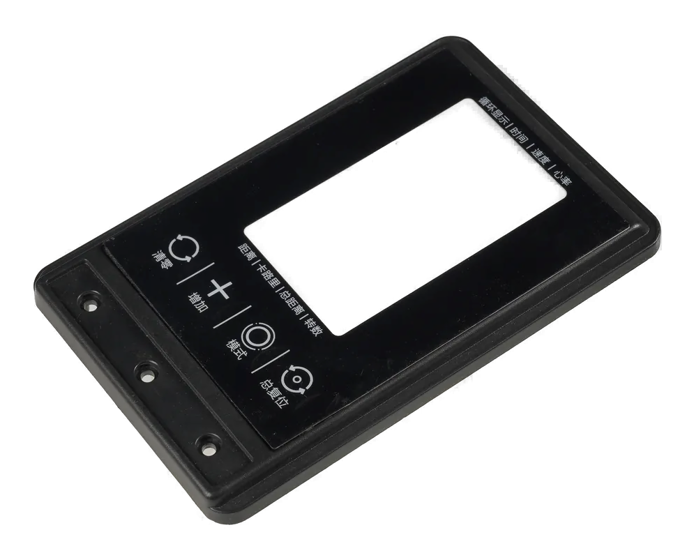
Enclosure-mounted front panel HMI assembly with bezel, controls, display, gasket, rear carrier, fasteners, and cable exit
Mounting state releasedpanel cutout, bezel, datums, gasket, compression, studs, fasteners, and rear clearance
Operator front integratedcontrols, display or indicators, carrier, rear parts, connector, cable exit, and labels
Cabinet boundary explicitfront module supplied; field wiring, PLC, cabinet, machine, and final approval separated

This Route Ends at a Mounting-Ready Front Module

The HMI family page covers several integration routes. This child page is specifically for the mechanical customer handoff: an operator module located to a panel cutout or equipment opening through released datums, gasket, fasteners, rear clearances, and cable direction.

The supplied front may use a printed overlay, rigid lens, membrane switch, silicone keypad, capacitive touch, display, indicators, PCB or FPC, carrier, and connector. The exact technologies matter less than the state in which the module reaches the enclosure.

The surrounding cabinet, DIN rail equipment, PLC, power distribution, field wiring, machine harness, safety circuits, application software, and complete-system certification are excluded unless separately listed.

Enclosure-Mounted Front Panel HMI Assemblies fit when:

  • the OEM wants one operator panel ready to locate and fasten into a released opening
  • bezel, controls, display, gasket, rear components, cable exit, and mounting hardware need one assembly owner
  • panel cutout, datums, compression, rear clearance, installation sequence, and service direction can be defined
  • the customer retains the wider cabinet, field wiring, PLC or machine logic, and final equipment validation

Six Controls Turn a Front Panel into an Installable Module

A front panel becomes useful when the OEM can locate, seal, fasten, connect, and service it without changing the approved interface.

01

Panel cutout and datums

Release control

Release cutout, corner radii, studs, holes, bezel overlap, locating surfaces, orientation, tolerance stack, and customer reference model.

If it is missing

The front looks correct but does not locate repeatably in the equipment opening.

02

Bezel, carrier, and rear structure

Release control

Define material, thickness, ribs, brackets, board supports, display mounts, fasteners, inserts, rear envelope, and service access.

If it is missing

The module flexes, collides with cabinet parts, or cannot be assembled in the intended direction.

03

Gasket and compression

Release control

Control material, path, joints, adhesive, compression target, stops, surface flatness, fastener pattern, and leak-path ownership.

If it is missing

Mounting creates uneven gaps, distorted controls, or an unverified sealing boundary.

04

Operator-front integration

Release control

Release controls, display or indicators, artwork, window, key openings, touch areas, lighting, cosmetic gaps, and shared datums.

If it is missing

The panel fits the cabinet while visible controls and feedback remain misaligned.

05

Rear connector and cable exit

Release control

Define connector, pinout, harness, strain relief, gland or pass-through, bend limits, rear clearance, grounding, and field-wiring handoff.

If it is missing

The module mounts but the cable cannot be connected, routed, or serviced safely.

06

Installation and acceptance

Release control

Name fasteners, torque or stop method, sequence, fit fixture, appearance, dimensions, inputs, display, lighting, connector output, labels, and protection.

If it is missing

Supplier and OEM install the same part differently and receive different fit or function.

Release the Front Panel by Cutout, Mounting State, and Rear Envelope

The customer drawing should show the physical module, the surrounding reference opening, and the exact state delivered for installation.

DecisionOptions to ReviewRelease Question
Front architecturePrinted overlay, rigid lens, bezel, membrane switch, silicone keys, capacitive touch, display, indicators, and labelsWhich visible and operator-facing parts arrive as one module?
Cutout and locationOpening, radii, overlap, holes, studs, locating tabs, datum scheme, orientation, tolerance, and customer CAD referenceHow does the module locate repeatably to the enclosure?
Sealing and fasteningGasket, adhesive, compression stops, screws, nuts, inserts, clips, torque, sequence, surface flatness, and leak pathsWhat installation state preserves fit, feel, appearance, and the intended seal boundary?
Rear assemblyCarrier, brackets, PCB or FPC, display support, components, covers, spacers, ventilation, rear envelope, and service accessWhat volume and access does the OEM reserve behind the panel?
Cable handoffConnector, pinout, harness, gland, pass-through, strain relief, ground, bend route, mating part, and field-wiring boundaryWhat connection state exists after the panel is fastened?
AcceptanceAppearance, dimensions, fit fixture, gasket state, input, lighting, display, connector output, fastener check, labels, packaging, and traceabilityWhich checks prove the front module and which remain cabinet or machine validation?
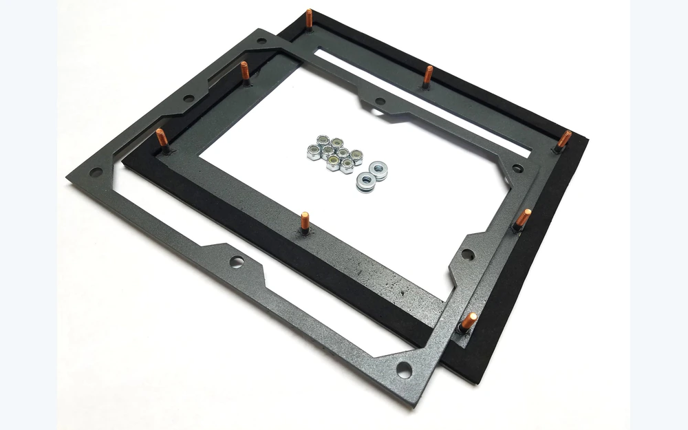
Exploded enclosure-mounted HMI panel with front, gasket, cutout reference, rear carrier, and fasteners
CUTOUT AND COMPRESSION

Design the Mounting Opening and Gasket as Part of the Product

Bezel overlap, corner radius, enclosure flatness, gasket width, fastener spacing, compression stops, cable exits, and rear supports determine whether the front can be installed consistently. The module and cutout should be reviewed as mating parts.

  • dimension the customer opening and module from a shared datum scheme
  • show gasket path, joints, compression direction, and structural stops
  • reserve rear clearance for boards, display, connectors, cables, and tools
  • approve the assembly in a representative cutout or fit fixture
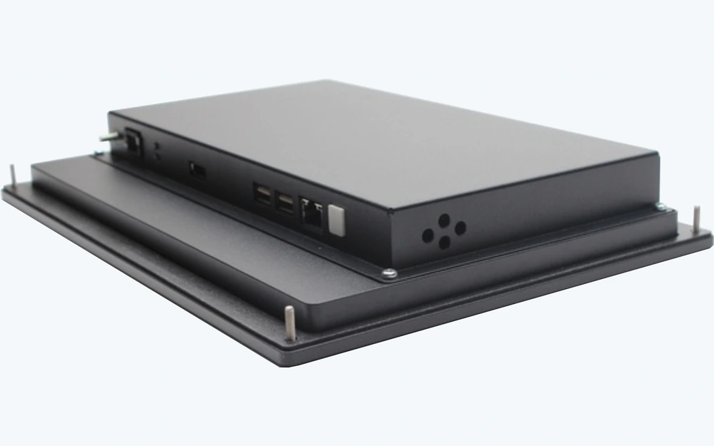
Finished front panel HMI module showing mounting datums, fasteners, rear connector, and protected handoff
CUSTOMER INSTALLATION

Ship the Panel in a State the Integrator Can Reproduce

Protective films, loose hardware, gasket liners, connector caps, labels, torque notes, installation order, and cable orientation influence the final result. The handoff package should prevent the integrator from guessing how the approved module was assembled.

  • identify installed, loose, customer-installed, and reference-only hardware
  • protect cosmetic surfaces, gaskets, connectors, cables, and adhesive liners
  • provide a released installation direction and mating connector reference
  • retain fit and function evidence against the shipped revision

Release the Assembly Through Five Controlled Decisions

01

Define the customer opening

Release panel cutout, overlap, datums, orientation, enclosure surface, rear envelope, installation direction, and service access.

02

Build the front architecture

Coordinate controls, display or indicators, bezel, carrier, rear components, gasket, fasteners, cable exit, and visible gaps.

03

Release mounting and wiring

Define compression, stops, hardware, sequence, connector, pinout, harness, strain relief, grounding, and field-wiring boundary.

04

Approve the installation state

Check appearance, dimensions, fit, gasket, inputs, display, lighting, connector output, labels, protection, and packaging.

05

Control module and cutout changes

Lock drawings, materials, hardware, fixtures, instructions, packaging, substitutions, notifications, and requalification triggers.

Diagnose Front Panel Problems at the Enclosure Handoff

01

Panel does not fit the opening

Compare cutout, radii, bezel overlap, locating features, studs, holes, datum scheme, orientation, fixture, enclosure revision, and tolerance stack.

02

Gap or gasket is uneven

Review surface flatness, gasket path, compression stops, fastener spacing, torque or sequence, carrier stiffness, adhesive, and rear interference.

03

Controls change after fastening

Check mounting load, rear support, display opening, PCB position, bezel clearance, gasket compression, fasteners, and enclosure deformation.

04

Cable cannot be connected or serviced

Inspect connector orientation, mating part, rear envelope, bend route, strain relief, gland, field-wiring path, tool access, and installation sequence.

Where Enclosure-Mounted Front Panel HMI Assemblies Fit

01

Industrial machine doors

Operator modules fitted to released equipment cutouts with controls, displays, gaskets, rear electronics, and cable handoff.

02

Control enclosures

Custom front panels supplied without assuming the wider cabinet, PLC, power distribution, or field wiring.

03

Medical equipment fronts

Cleanable mounted interfaces with controlled appearance, display, keys or touch, gasket, connectors, and installation evidence.

04

Transportation consoles

Panel-mounted operator controls coordinated with night graphics, vibration support, cable route, rear clearance, and host electronics.

05

Building-control panels

Wall or cabinet fronts with display, input, carrier, sealing boundary, mounting hardware, and serviceable connector access.

06

Foodservice equipment

Durable operator panels combining graphics, keys or touch, display or indicators, gasket, fasteners, and repeatable opening fit.

RFQ PACKAGE

Send the Panel Cutout, Front Module, and Rear Envelope

The most useful starting point is the customer enclosure model or cutout drawing together with the operator-front concept and intended cable direction.

  • panel cutout, radii, overlap, holes, studs, locating features, datums, orientation, enclosure material, and surface flatness
  • front outline, bezel or carrier, controls, display or indicators, artwork, windows, lighting, labels, and cosmetic zones
  • gasket material and path, compression, stops, adhesive, fasteners, inserts, torque or sequence, and intended seal boundary
  • rear PCB or FPC, display bracket, components, covers, spacers, ventilation, rear envelope, tool access, and service direction
  • connector, pinout, harness, cable exit, gland or pass-through, strain relief, grounding, mating part, and field-wiring boundary
  • prototype quantity, annual estimate, fit and function fixture, installation notes, packaging, traceability, and change control
Send Front Panel HMI Files

Enclosure-Mounted Front Panel HMI Assemblies FAQ

How is this different from the HMI Assembly family page?

The family page compares several product routes. This page specifically owns the mounting-ready mechanical handoff to a customer panel cutout or equipment opening, including bezel or carrier, gasket, fasteners, rear envelope, cable exit, and installation state.

Does the assembly include the full control cabinet?

No. The surrounding cabinet, DIN rail equipment, power distribution, PLC, field wiring, machine harness, safety circuits, application software, and complete certification are excluded unless separately contracted.

Can the gasket and mounting hardware be supplied?

Yes, when gasket path and material, compression, stops, fasteners, inserts, sequence, enclosure surface, fit fixture, packaging, and customer installation responsibilities are released.

What should the customer enclosure drawing include?

Include the cutout, corner radii, datums, holes or studs, overlap, surface material and flatness, rear clearance, interfering components, cable route, installation direction, tool access, and mating connector.

Can an IP target be guaranteed by the front panel alone?

No universal ingress result is implied. The front module, gasket, enclosure surface, fasteners, cable or gland, installation, aging, field conditions, and complete-equipment test method must be validated together.

Related HMI and Interface Routes

Release the front module and the customer cutout as mating parts.

JASPER can review the bezel or carrier, controls, display or indicators, gasket, fasteners, rear assembly, connector, cable exit, mounting datums, fit evidence, installation state, and packaging as one front panel HMI assembly.

Start Front Panel HMI ReviewContact Engineering