Dongguan, Guangdong 523927, China[email protected]+86 136 3262 5290
Home / Products / HMI Assembly / Silicone Keypad HMI Assemblies for OEM Controls
RAISED-KEY OPERATOR MODULES

Silicone Keypad HMI Assemblies for OEM Controls

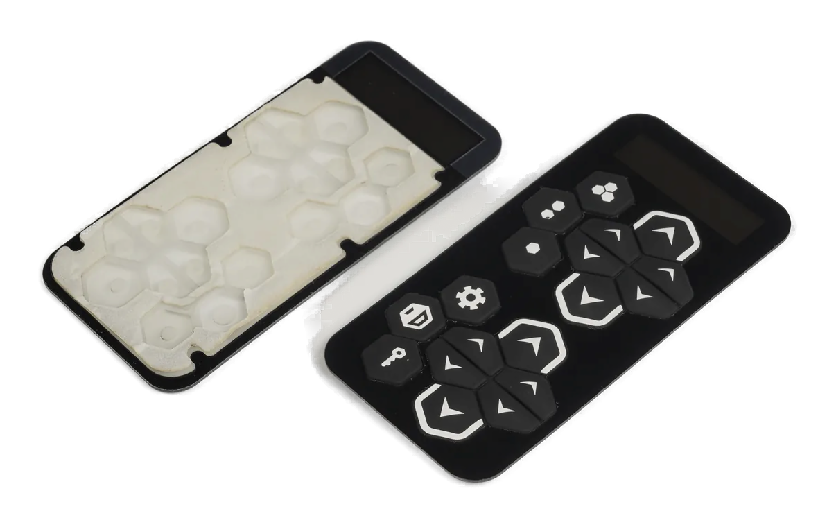
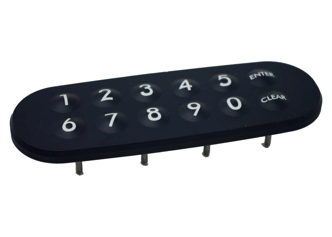
A silicone keypad HMI assembly combines the molded keymat with the wider operator front, PCB contact system, lighting or indicators, display area, carrier or bezel, connector, gasket, mounting features, and released assembly checks. It is the route for a complete raised-key module, not only a loose keypad or keypad-to-PCB subassembly.

Silicone keypad HMI assembly with raised keys, display area, PCB, lighting, carrier, and connector
Key feel in contexttravel, force, web, stop, PCB support, bezel clearance, and installed compression
Front module integratedkeymat, graphics, display area, lighting, PCB, carrier, connector, and gasket
Handoff protectedmounting datums, rear clearance, labels, cosmetic protection, test records, and packaging

The HMI Route Adds the Operator Front and Enclosure Handoff

A silicone keypad assembly usually owns the molded keypad, contact pills, PCB relationship, and selected lighting or carrier parts. This HMI route is broader: it coordinates the full visible front, display or indicator region, rear support, connector, sealing, mounting, and customer installation state.

Key feel is created by molded geometry but changed by the bezel, PCB location, compression, support, fastener load, coating, legends, and enclosure clearance. Approval should occur in a production-intent module rather than on a loose keymat.

The display, controller, board components, harness, enclosure parts, and final product tests are included only when the bill of material and responsibility matrix say so.

Silicone Keypad HMI Assemblies for OEM Controls fit when:

  • raised molded keys must be integrated with a larger operator front, display area, PCB, and rear support
  • key travel, force, lighting, legends, sealing, and enclosure fit must be approved in one module
  • the customer wants a keyed connector and mounting-ready handoff rather than separate keypad and electronics parts
  • the OEM can validate host software, machine logic, safety, and finished-equipment compliance

Six Controls Keep the Raised-Key HMI Consistent After Assembly

The molded keypad, visible front, PCB, and enclosure must share one geometry and one acceptance state.

01

Key geometry and feel

Release control

Release key tops, web, travel, force targets, hard stops, contact pills, venting, actuation map, and representative samples.

If it is missing

The molded keypad looks correct but keys bind, feel uneven, or overload the PCB after installation.

02

Legends and surface

Release control

Define molded color, printing, laser etching, coating, light transmission, texture, cosmetic zones, abrasion exposure, and cleaning.

If it is missing

Legends or coating pass loose-part review but fail after lighting, handling, or installed use.

03

PCB contact interface

Release control

Control contact pad finish, geometry, alignment, support, component keep-outs, LEDs, test points, connector, and board datum.

If it is missing

Contacts intermittently close because the keymat and PCB move or compress differently.

04

Display and front architecture

Release control

Release display or indicator area, bezel, overlay or lens, window, key openings, light block, carrier, and shared datums.

If it is missing

The keypad fits while the display, window, or front graphics remain visibly misaligned.

05

Sealing and mounting

Release control

Define flange, gasket, compression, bezel clamp, fasteners, studs, rear clearance, panel cutout, and assembly sequence.

If it is missing

Sealing load changes key feel or creates wrinkles, gaps, or trapped interference.

06

Inspection and handling

Release control

Name visual, dimensional, force sample, continuity, lighting, fit, connector, protection, labels, trays, and change records.

If it is missing

Approved key surfaces, legends, or contacts are marked, mixed, or deformed before customer installation.

Release the Silicone HMI by Key, Board, Front, and Mounting Boundary

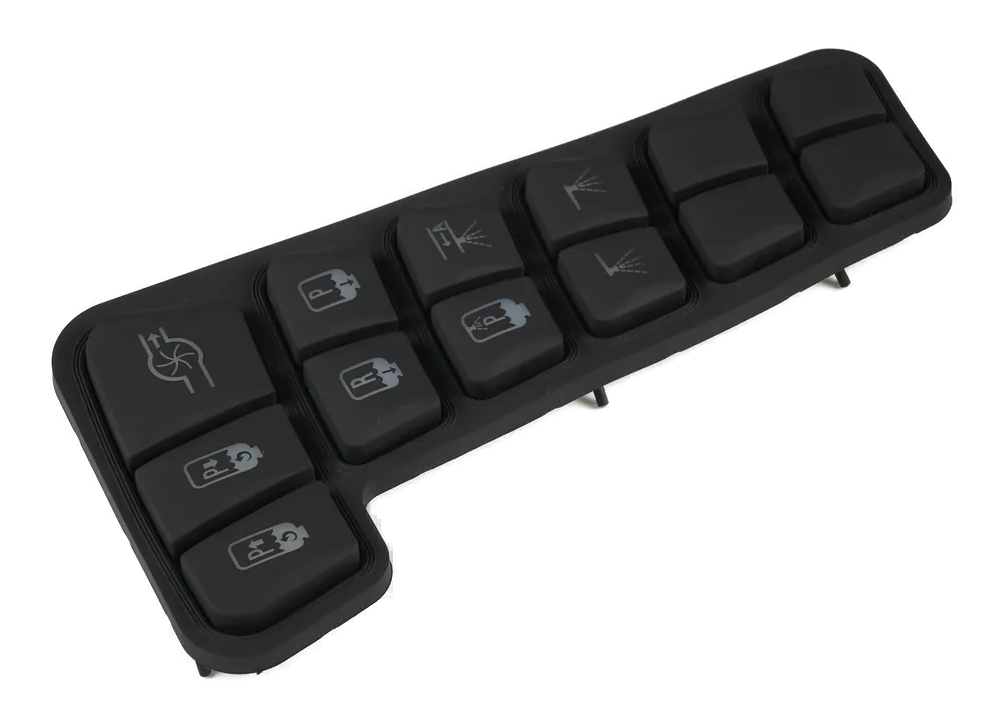
The approved drawing should connect molded geometry to the PCB, visible front, display area, carrier, enclosure, and customer connector.

DecisionOptions to ReviewRelease Question
Keypad constructionSilicone grade, color, key profile, web, travel, force, stop, carbon or conductive contact, venting, and tolerancesWhich molded features create the approved feel in the installed module?
Legends and lightingPrinted, laser-etched, coated, translucent, light-blocked, backlit, indicator, day and night appearanceWhich visible states and durability expectations become the approval reference?
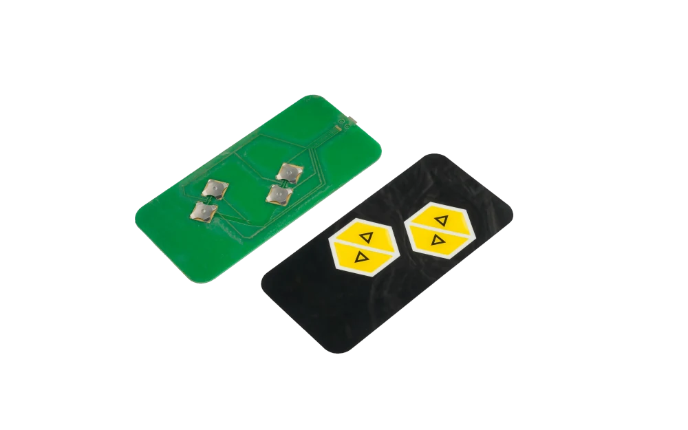
PCB interfaceContact pads, plating, board thickness, support, LEDs, components, connector, pinout, test points, and board retentionWhat board state is supplied and how is keypad alignment maintained?
Front and displayBezel, overlay, lens, display or window, black mask, openings, carrier, brackets, and cosmetic gapsHow do keys, graphics, display, and enclosure align from shared datums?
Sealing and mountingKeypad flange, gasket, compression, fasteners, studs, panel cutout, rear clearance, and installation directionWhat mounting load preserves feel, seal, and appearance?
EvidenceAppearance, dimensions, force sample, continuity, lighting, fit fixture, connector output, packaging, traceability, and retained sampleWhich checks prove the module and which remain customer system validation?
Silicone keypad HMI module aligned to a fixture for key feel, fit, and connector inspection
INSTALLED KEY FEEL

Approve Travel and Force with the Bezel, PCB, and Fasteners Present

A loose keypad cannot reproduce bezel clearance, PCB support, mounting compression, hard-stop position, gasket load, or enclosure interference. The sample fixture should hold the same datums and loads planned for production.

  • measure or compare representative keys at center, edge, and display-adjacent locations
  • reproduce PCB support and fastener load during approval
  • inspect return, sticking, double contact, and hard-stop behavior
  • retain an approved module rather than only a loose molded sample
Finished silicone keypad HMI assembly with display, lighting, rear carrier, and connector
VISIBLE FRONT

Coordinate Legends, Lighting, Display, and Cosmetic Gaps

The operator sees one product even when the front contains silicone, a bezel or overlay, a lens, a display, indicators, and separate light paths. Day, powered, unpowered, and low-light states should be approved at the assembled front.

  • release color targets and lit or unlit samples under named viewing conditions
  • control light block, diffusion, leakage, and display-window registration
  • define acceptable gaps, flushness, texture, and transitions between materials
  • protect coated and printed key surfaces through test and shipment

Release the Assembly Through Five Controlled Decisions

01

Define the operator feel

Release key map, profile, force, travel, stop, legends, surface, lighting, display, and user states.

02

Align molded and rigid parts

Coordinate keymat, PCB, bezel, lens or overlay, display, carrier, gasket, fasteners, datums, and clearances.

03

Close electrical interfaces

Confirm contacts, LEDs, components, connector, pinout, cable route, grounding, test points, and supplied board state.

04

Approve the installed module

Review appearance, key feel, return, continuity, lighting, display relationship, fit, connector, protection, and packaging.

05

Control repeat production

Lock tool, materials, colors, legends, coatings, PCB revision, fixtures, work instructions, substitutions, and requalification.

Diagnose Silicone HMI Problems in the Installed Module

01

Keys bind or feel uneven

Check bezel openings, web clearance, PCB support, hard stops, fastener load, gasket compression, molded revision, and enclosure interference.

02

Contacts are intermittent

Review contact pill, PCB pad, alignment, board retention, contamination, compression, venting, connector, and electrical test state.

03

Lighting or legends look wrong

Compare coating, print, laser depth, silicone color, LED position, light block, diffusion, display state, viewing condition, and approved sample.

04

Module does not fit

Check shared datums, carrier, panel cutout, display bracket, gasket, studs, fasteners, rear components, connector direction, and drawing revision.

Where Silicone Keypad HMI Assemblies Fit

01

Industrial handhelds

Raised-key modules with tactile operation, PCB contacts, display areas, sealing, and robust enclosure handoff.

02

Medical instruments

Cleanable molded controls with controlled legends, key feel, display relationship, electronics, and assembly evidence.

03

Transportation controls

Glove-friendly operator modules coordinated with backlighting, vibration support, connectors, and night-use graphics.

04

Marine and outdoor equipment

Raised sealed controls with gasket, carrier, display or indicators, cable routing, and customer enclosure validation.

05

Test and measurement

Function keys, rotary or navigation clusters, display areas, PCB electronics, and serviceable front modules.

06

Appliances and foodservice

Durable tactile controls combining molded color, legends, lighting, display, PCB, bezel, and repeatable mounting.

RFQ PACKAGE

Send the Keymat, PCB, Front, and Enclosure Interfaces Together

A useful review starts with the desired key feel and the rigid geometry that will control it after assembly.

  • key map, profiles, force and travel targets, hard stops, contact type, venting, and representative user conditions
  • silicone color, surface, legends, printing, laser etching, coating, backlighting, indicators, and cosmetic zones
  • PCB outline, contact pads, components, LEDs, test points, connector, pinout, support, and board revision
  • bezel, overlay or lens, display or window, carrier, bracket, shared datums, openings, and visible gaps
  • gasket, compression, studs, fasteners, panel cutout, rear clearance, cable exit, and installation sequence
  • prototype quantity, annual estimate, force and visual inspection, fit fixture, packaging, traceability, and change control
Send Silicone HMI Files

Silicone Keypad HMI Assemblies for OEM Controls FAQ

How is this different from a silicone keypad assembly?

A silicone keypad assembly focuses on the molded keypad, PCB contacts, lighting, connector, and selected carrier parts. This HMI route adds the wider visible front, display or indicator region, enclosure mounting, gasket, rear clearance, and complete customer handoff state.

Can the PCB and display be included?

Yes, when the exact board and display, source, components, configuration, mounting, interfaces, tests, lifecycle, and replacement rules are explicitly listed.

How should key feel be approved?

Approve representative keys in a production-intent module or fixture with the actual bezel clearance, PCB support, fastener load, gasket compression, hard stops, and enclosure constraints.

Can legends and backlighting be customized?

Molded colors, printed or laser-etched legends, coatings, translucent regions, light blocking, and backlighting can be reviewed against named day, powered, unpowered, and low-light approval states.

Does the assembly include final waterproof or regulatory approval?

No universal ingress or regulatory result is implied. The finished enclosure, installation, field wiring, electronics, software, environment, test method, and complete product remain part of the OEM validation plan.

Related HMI and Interface Routes

Approve the key feel where the operator will actually use it.

JASPER can review the molded keypad, legends, lighting, PCB contacts, display area, bezel or carrier, connector, gasket, mounting, inspection, and packaging as one silicone keypad HMI assembly.

Start Silicone HMI ReviewContact Engineering