
Supplied scope
Control Failure modeA missing spacer, connector, fastener, or liner appears after purchasing assumes a complete module.
A silicone keypad assembly places responsibility for the molded keypad, circuit, contacts or actuators, LEDs, connector, spacer, carrier, enclosure datums, functional test, packaging, and controlled change path inside one released module.
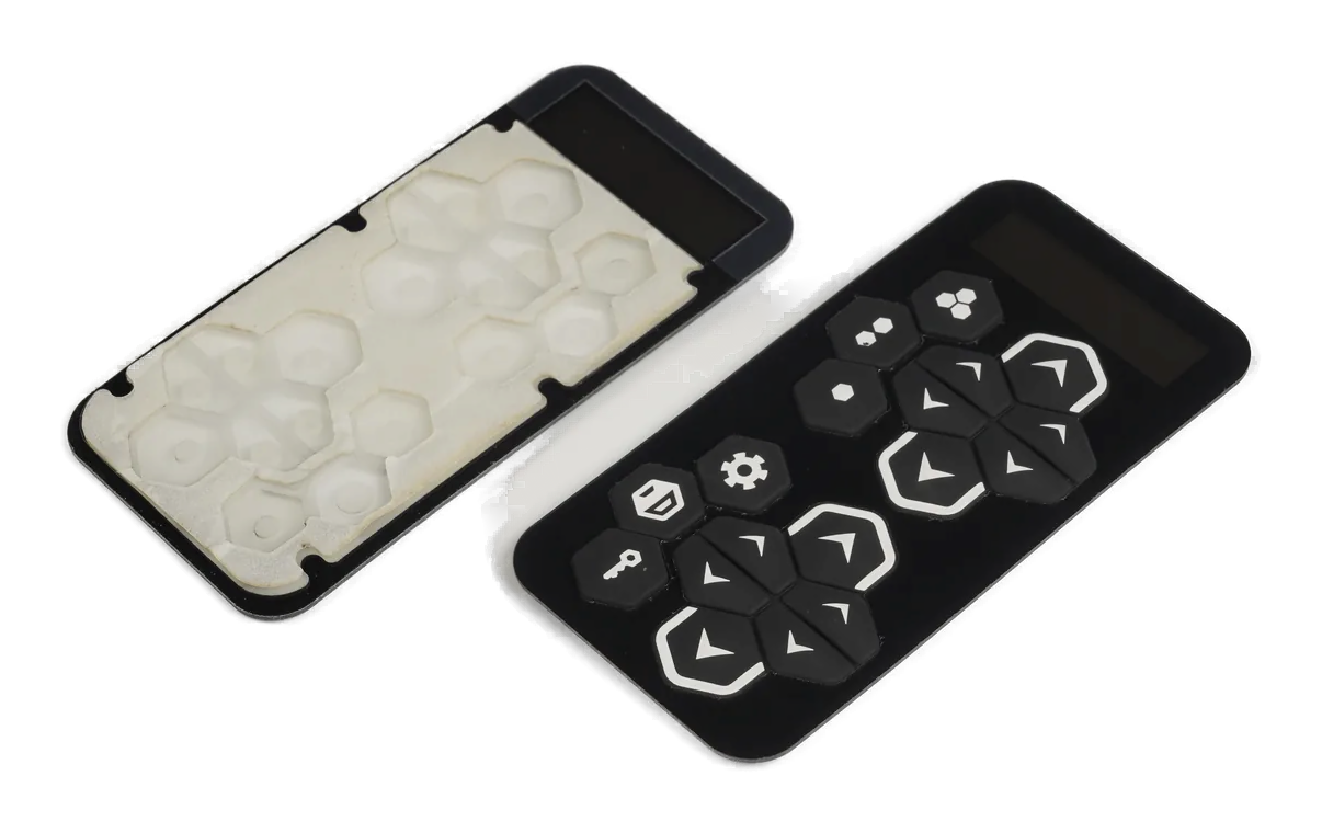
A silicone keypad assembly combines the molded keypad with some or all of the PCB, FPC, PET or membrane circuit, contacts or actuators, LEDs, connector, spacer, adhesive, carrier, bezel, hardware, and test boundary required by the OEM.
The useful scope is not defined by part count. It is defined by who owns contact alignment, key height, support, hard stop, circuit deflection, lighting, connector routing, enclosure fit, functional inspection, packaging, and change control.
Use this route when purchasing or engineering needs one accountable supplied module. Use the other child routes when the primary need is a molded keypad whose contact, optical, or legend interface will be integrated elsewhere.
A bundled shipment is not an assembly specification unless responsibility and evidence are explicit.
A missing spacer, connector, fastener, or liner appears after purchasing assumes a complete module.
Release keypad, circuit, carrier, housing, key, stop, support, compression, and fastener relationships.
Failure modeKeys bind or change feel because separate drawings use different origins.
Define circuit type, pinout, connector, contacts, LEDs, components, test points, load, and mating boundary.
Failure modeThe assembly passes continuity but does not interface with the OEM controller.
Control LED, artwork, coating, diffuser, barriers, spacer, housing walls, powered state, and viewing condition.
Failure modeThe loose module looks correct but leaks light after enclosure installation.
Name key operation, continuity or resistance, matrix, LED, connector, visual, dimensional, and fixture checks.
Failure modeFinal inspection confirms parts are present without proving the module works.
Define protection, orientation, liners, ESD where relevant, traceability, approved revision, and requalification triggers.
Failure modeContacts, coatings, or connectors are damaged or substituted after inspection.
An assembly drawing should let both companies identify what JASPER supplies, what the OEM supplies, how the two mate, and what evidence authorizes shipment.
| Decision | Options to Review | Release Question |
|---|---|---|
| Keypad construction | Conductive contact, actuator, backlit, laser-etched, molded window, edge seal, or project combination | Which finished keypad revision belongs in the module? |
| Circuit and components | PCB, FPC, PET, membrane circuit, LEDs, resistors, connectors, domes, sensors, or project electronics | Which circuit revision, pinout, finish, and populated state are controlled? |
| Support and carrier | Spacer, adhesive, plate, carrier, bezel, ribs, stops, fasteners, gasket, or enclosure feature | What maintains alignment, height, compression, and service access? |
| Mating interface | OEM enclosure, controller, display, cable, hardware, seal, grounding, or neighboring mechanism | Which customer boundary is required for installed approval? |
| Functional evidence | Continuity, resistance, matrix scan, LED check, key operation, dimensions, visual, or fixture test | Which test proves the shipped module is ready for its next step? |
| Production control | BOM, approved sources, revision, work instruction, fixture, traceability, packaging, and requalification | What prevents an uncontrolled part or process change? |
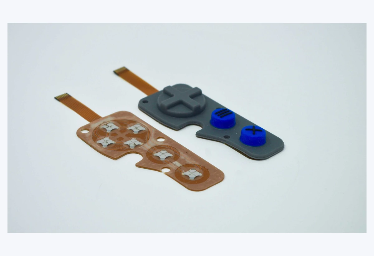
The keypad, contacts, circuit, LEDs, spacer, connector, carrier, and enclosure cannot each be centered independently. Their released datums must preserve contact overlap, key travel, hard stops, light paths, and connector access after tolerance movement.
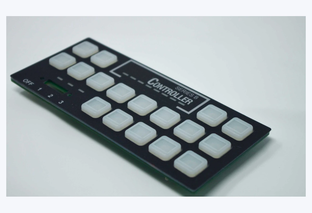
Final inspection should represent the supplied boundary. A keypad assembly may need visual, dimensional, key-operation, contact, LED, connector, fit, packaging, and project-specific evidence before shipment.
List JASPER-supplied parts, OEM-supplied parts, mating interfaces, responsibilities, and required evidence.
Align keypad, contact, circuit, support, carrier, connector, housing, pinout, and tolerance movement.
Lock materials, approved sources, artwork, circuit, assembly sequence, cleaning, fixtures, and work instructions.
Check fit, key operation, contact, lighting, connector access, sealing interface, removal, and packaging.
Use revision control, functional inspection, traceability, packaging, and named requalification triggers.
Review carrier height, housing ribs, compression, stop location, circuit support, fasteners, and neighboring keys.
Check contact landing, board deflection, datum movement, contamination, spacer height, and connector handling.
Review enclosure partitions, spacer color, LED position, edge paths, keypad compression, and neighboring keys.
Review insertion path, bend radius, strain relief, latch access, assembly sequence, and retained cable length.
Keypad, PCB or flex, connector, carrier, and functional inspection supplied for compact field equipment.
Controlled modules reviewed around cleaning, operator use, circuit, lighting, enclosure, and evidence.
Seat, console, service, and specialty controls with shared mechanical, electrical, and optical datums.
Modules whose keypad edge, circuit protection, connector, housing, and exposure are reviewed together.
PIN pads, remotes, alarm controls, and readers supplied with circuit and functional inspection.
Drop-in molded control modules combining color, symbols, lighting, PCB, connector, and mounting support.
Early files can be incomplete. A keypad concept, circuit image, enclosure model, connector requirement, and supplied-scope note are enough to begin defining responsibility.
The scope can include the molded keypad, contacts or actuators, PCB, FPC, PET or membrane circuit, LEDs, components, connector, spacer, adhesive, carrier, bezel, hardware, and functional inspection. The released drawing and BOM define the actual boundary.
Yes, when the project defines the circuit revision, contacts, LED and component scope, connector, carrier or support, enclosure interface, assembly process, functional test, packaging, and change control.
No universal enclosure rating should be assumed. Sealing depends on the complete housing, keypad edge, gasket or adhesive, compression, tail or connector path, fasteners, exposure, assembly process, and agreed test.
Match the test to the supplied boundary. It may include key operation, continuity or resistance, matrix behavior, LEDs, connector pinout, dimensions, appearance, fit fixture, and project-specific conditions.
Approve fit, key feel and return, contact function, lighting, connector access, support, compression, sealing interface, service path, appearance, packaging, and the controlled revisions used.
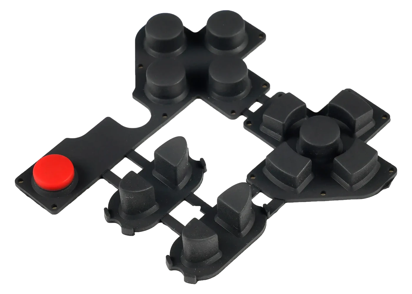
Review contact geometry and circuit landing before the complete module is released.
Review Resource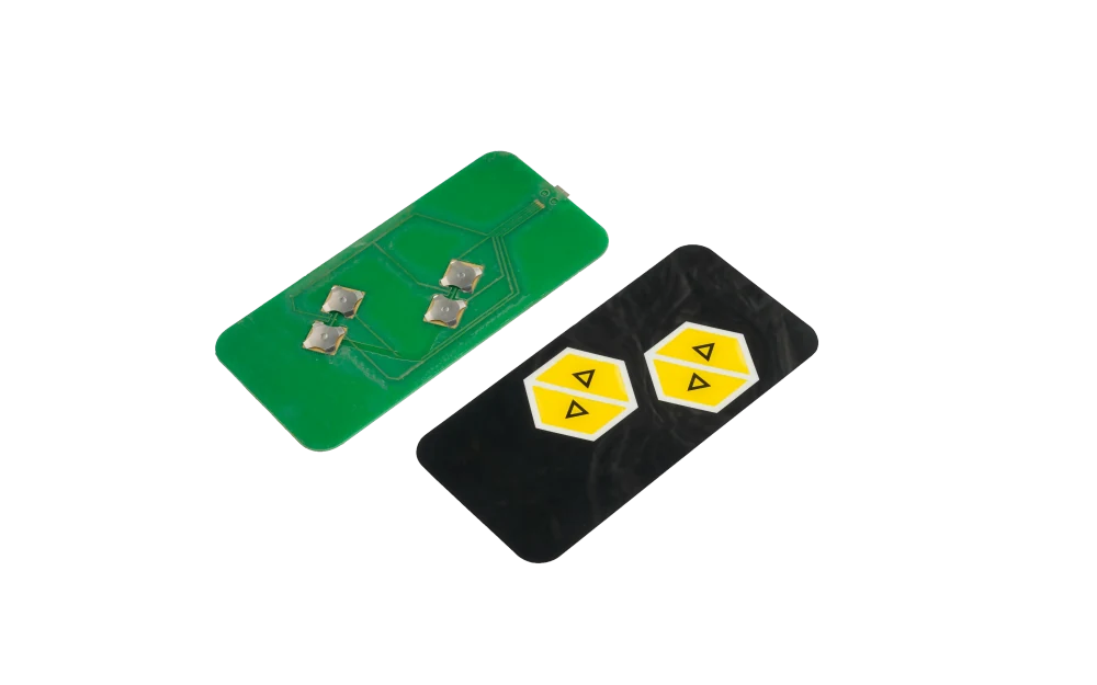
Compare a wider front-panel assembly route when displays, overlays, and enclosure parts join the module.
Review Resource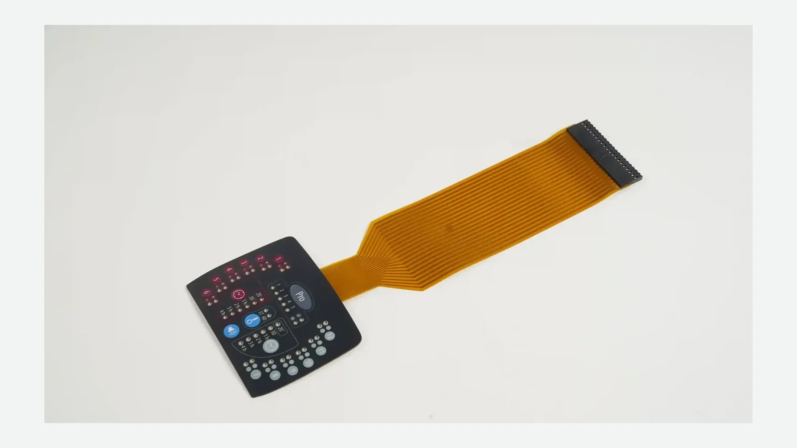
Plan connector access, bend radius, strain relief, mating parts, and installation sequence.
Review ResourceJASPER can review the molded keypad, circuit, contact, lighting, connector, carrier, enclosure, functional test, packaging, and change control as one silicone keypad assembly.
Share the project basics. JASPER will review the stack, materials, connector, quantity, and production risks.