
Contact route
ControlRelease the pill, conductive coating, metal contact, dome actuator, or non-conductive actuator and its substitution boundary.
Failure modeA generic conductive callout allows a different electrical and tactile result.
A conductive rubber keypad must move each molded key through the intended force curve, place the released contact on the circuit landing, close consistently, overtravel without damage, and return after the enclosure is assembled.
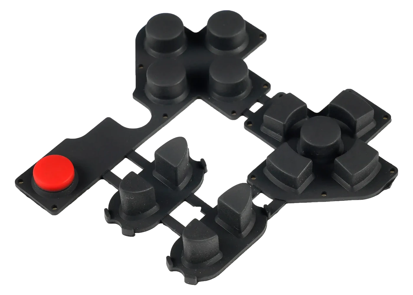
A conductive rubber keypad uses a molded key to bring a conductive element or actuator into a controlled relationship with a PCB, FPC, PET circuit, membrane circuit, or another released switch interface.
Carbon pills are common, but the words carbon pill do not define pill material, geometry, resistance behavior, bond to the silicone, position, mating pad, force curve, environment, or test method. Those fields must be released for the project.
Use this route when electrical contact and installed switching are the primary risks. Move to the assembly route when JASPER must also own the circuit, connector, LEDs, carrier, enclosure interface, and final module test.
Intermittent switching usually comes from an uncontrolled interface, not from the visible legend.
Release the pill, conductive coating, metal contact, dome actuator, or non-conductive actuator and its substitution boundary.
Failure modeA generic conductive callout allows a different electrical and tactile result.
Control diameter or outline, thickness, location, orientation, bond, and finished relation to the key.
Failure modeThe contact misses part of the circuit landing after molding variation.
Release pad pattern, area, spacing, finish, contamination control, datum, and board or flex condition.
Failure modeA clean loose contact test hides poor installed overlap or surface condition.
Define key cap, web, force curve, closure point, overtravel, stop, support, and return.
Failure modeThe key bottoms before closure, stays partly actuated, or overloads the contact.
Define resistance or continuity method, fixture, force, dwell, conditioning, sample, and acceptance.
Failure modeOne unloaded meter reading is treated as production evidence.
Control release residue, silicone oil, dust, handling, packaging, circuit cleaning, and inspection.
Failure modeContamination changes the contact surface after the molded part passes appearance.
The drawing and test plan should let molding, circuit, assembly, and inspection teams reproduce the same installed switching condition.
| Decision | Options to Review | Release Question |
|---|---|---|
| Contact method | Carbon pill, conductive compound, conductive coating, metal contact, dome actuator, or non-conductive actuator | What closes the circuit, and what properties and substitutions are controlled? |
| Contact position | Finished location, diameter or outline, orientation, embedment, bond, and datum | How much landing overlap remains after all molded and assembly tolerances? |
| Circuit interface | PCB, FPC, PET, membrane circuit, plated pad, printed pad, or project-defined contact | What pad geometry, finish, cleanliness, support, and deflection are approved? |
| Key behavior | Force curve, travel path, closure point, overtravel, stop, return, and neighboring-key interaction | Where does contact closure occur relative to bottoming and housing support? |
| Electrical test | Continuity, resistance, chatter, simultaneous key, matrix, conditioning, and repeated actuation | Which fixture, force, dwell, sample, and acceptance values prove function? |
| Installed evidence | Loose keypad, keypad plus circuit, installed first article, environmental sample, and retained reference | Which assembly state authorizes production and which changes require requalification? |
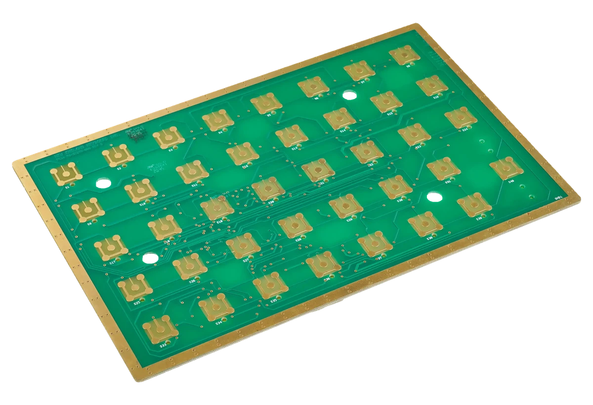
A centered CAD image is not the worst-case installed position. Review molded shrink, contact placement, board registration, enclosure datums, spacer thickness, key movement, and any circuit deflection before finalizing the landing.
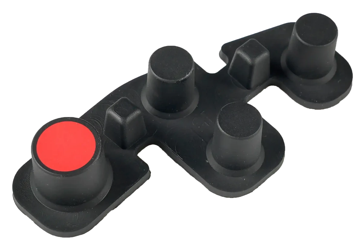
Closure, tactile response, overtravel, bottoming, and return are related but different events. Their order should be intentional and measured in the installed support condition.
Record the circuit, operator, key use, environment, electrical expectation, and failure consequence.
Review finished contact geometry, PCB landing, datums, tolerance movement, support, and compression.
Set key geometry, web, closure point, overtravel, hard stop, return, and neighboring-key behavior.
Measure force, travel, continuity or resistance, contamination response, fit, and return in the real assembly.
Lock compound, contact, tool, circuit, cleaning, inspection, packaging, and requalification triggers.
Check contact-to-pad overlap, circuit support, contamination, key angle, compression, and installed datum movement.
Review contact material and geometry, pad finish, pressure, contamination, conditioning, and measurement fixture.
Separate the closure point from the hard stop and review web geometry, support height, circuit deflection, and overtravel.
Review web restraint, housing ribs, compression, material state, dwell, temperature, and adjacent key interaction.
Molded operator keys over PCB or flex circuits with project-defined dirt, glove, and impact conditions.
Controls whose contact, cleaning, installed stack, and inspection evidence can be released together.
Seat, remote, console, service, and specialty interfaces with a controlled circuit landing.
PIN pads, remotes, and alarm controls requiring repeated contact closure and visible wear review.
Molded keys over a PCB or membrane circuit where key feel and circuit closure must remain aligned.
Installed keypads reviewed around moisture paths, circuit protection, connector routing, and enclosure support.
A contact review is more useful when the molded drawing, circuit pattern, enclosure support, and electrical test expectation arrive together.
It is a molded silicone keypad whose key movement brings a conductive element or actuator into contact with a released PCB, FPC, PET, membrane, or other circuit interface.
No. Carbon contacts are common, but the correct route depends on electrical behavior, mating circuit, key geometry, tactile requirement, environment, production evidence, and cost. Compare complete constructions rather than one contact name.
Common causes include poor landing overlap, circuit deflection, contamination, uncontrolled stack height, contact rocking, insufficient pressure, early bottoming, or installed datum movement. The exact cause needs evidence from the working assembly.
Yes. Share the circuit drawing, pad finish, keypad geometry, enclosure support, connector path, and electrical test expectation so the landing and installed tolerance stack can be reviewed together.
Approve geometry, fit, force and travel behavior, closure, overtravel, continuity or resistance, return, contamination controls, circuit alignment, and the installed condition required by the project.
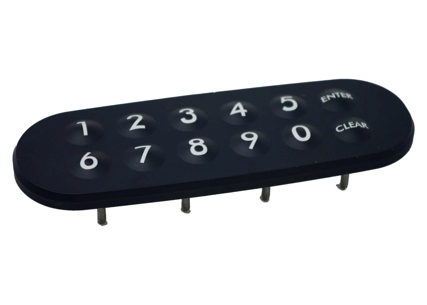
Return to the product family to compare contact, lighting, legend, and assembly routes.
Review Resource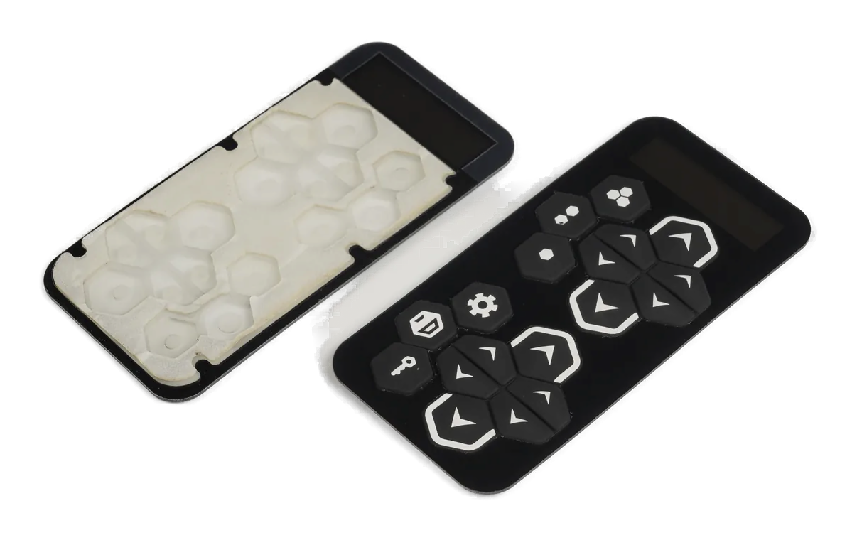
Extend the responsibility through the PCB or FPC, connector, carrier, and final test.
Review Resource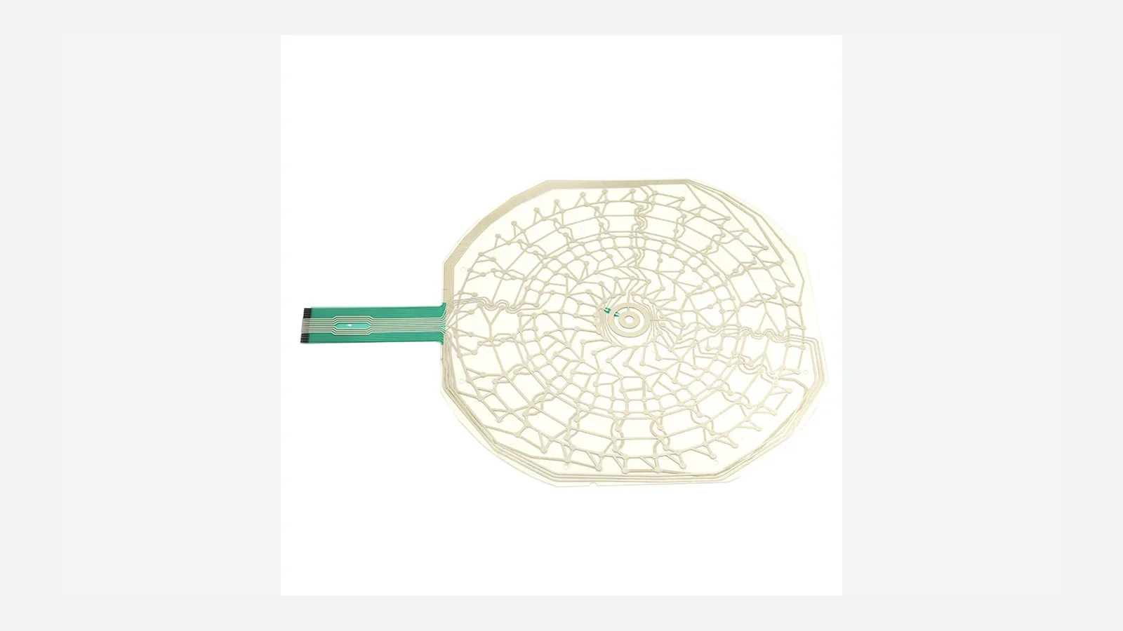
Review routing, contact geometry, connectors, test access, and installed circuit behavior.
Review ResourceJASPER can review the molded key, contact, PCB or flex landing, force path, enclosure support, electrical evidence, and production controls as one conductive rubber keypad.
Share the project basics. JASPER will review the stack, materials, connector, quantity, and production risks.