
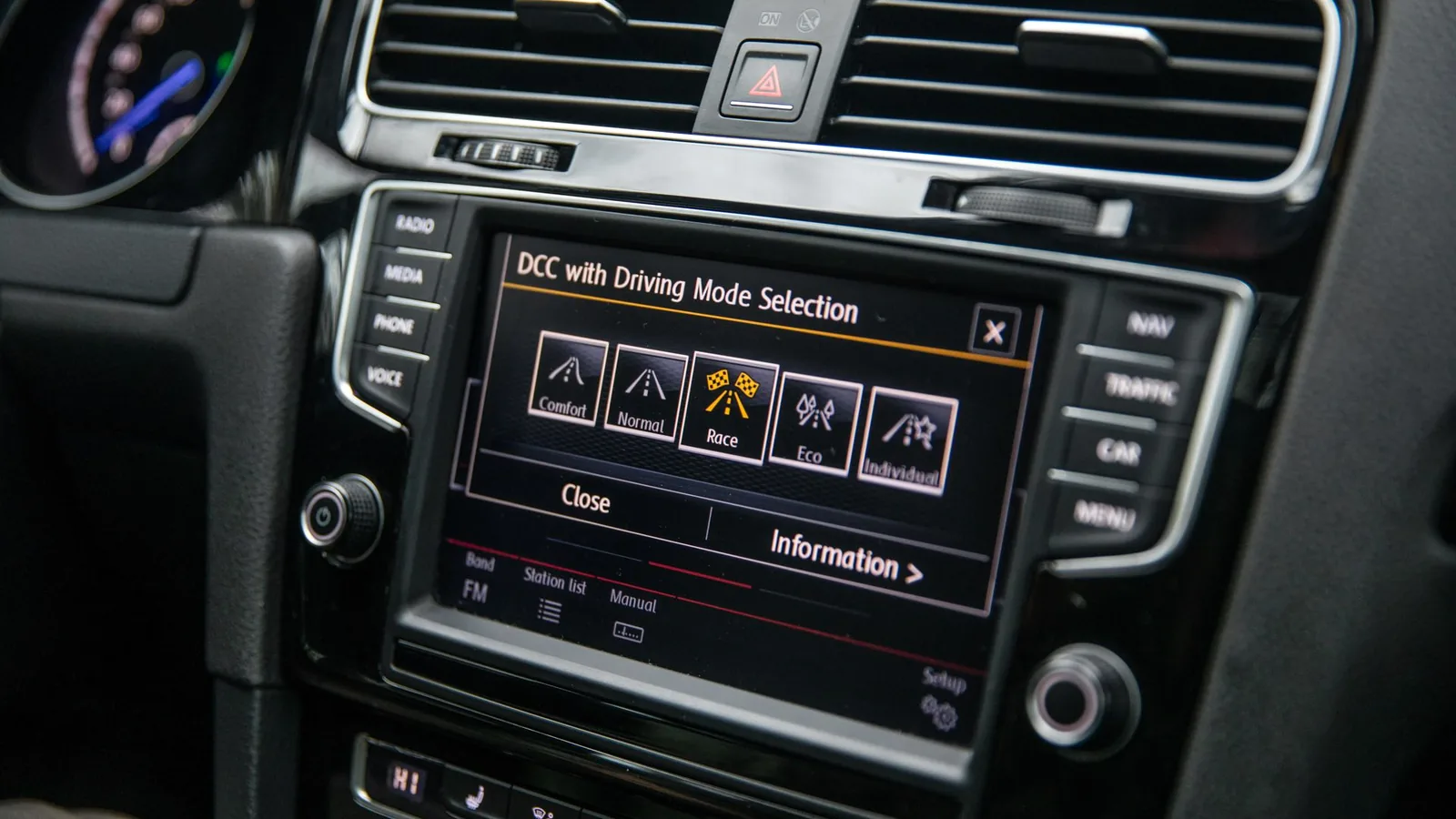
Allocate every control to a vehicle state first
An automotive membrane switch is only one physical part of a vehicle HMI. Before selecting key technology, artwork, or backlighting, define who uses each function, whether the vehicle is moving, what feedback confirms the action, and how a fault is handled. That allocation gives the control panel an engineering brief instead of a list of icons.
Vehicle moving
The driver may have limited glance time, one available hand, road vibration, changing light, gloves, and competing information.
- Interface direction
- Reserve stable positions and direct feedback for functions the vehicle program allows while moving. Separate frequent actions from setup, text entry, deep menus, and service functions.
- Release evidence
- Review reach, target identity, tactile reference, actuation, display or tell-tale response, error prevention, cancellation, lockout, and recovery in the complete cockpit and software state.
Vehicle stopped or parked
Configuration, pairing, personalization, charging setup, seat or cabin adjustment, diagnostics, and detailed menus can use a different interaction depth.
- Interface direction
- Define which tasks become available only when the OEM's vehicle-state logic permits them. Keep status and next-step feedback clear when the display, fixed keys, and mobile or remote interfaces overlap.
- Release evidence
- Exercise entry and exit conditions, saved settings, timeout, power cycle, interrupted setup, invalid input, shared-driver variants, language, and the transition back to driving.
External, charging, and service operation
Technicians, fleet operators, emergency users, or charging customers may work outside the normal seated-driver position and may wear gloves or encounter weather and dirt.
- Interface direction
- Separate production-vehicle controls from service tools, charging accessories, lift or auxiliary equipment, external panels, and specialty-vehicle functions with their own exposure and authority rules.
- Release evidence
- Validate access, labels, authentication or enable state, gloves, lighting, environmental exposure, cable and connector movement, service replacement, and return-to-operation checks.
The installation zone changes the interface brief
A center-console control, steering-wheel key, door switch, commercial-vehicle panel, charging interface, and workshop controller may all be called automotive electronics. Their users, sight lines, touch references, housing geometry, environment, and release records are not interchangeable.
Center stack and console
Climate, media, drive-mode, seat, charging, and convenience controls share limited area with displays, storage, cupholders, trim, and changing software functions.
Coordinate fixed versus screen functions, hand approach, unpowered graphics, night lighting, spill and cleaner exposure, decorative trim, display datums, and harness access.
Steering wheel and column
Controls near the driver's normal hand position need clear grouping and feedback while the wheel, hand angle, and road load move.
Define permitted function, reach, key separation, tactile cue, force, accidental contact, illumination, wiring or clock-spring boundary, trim fit, and full vehicle validation.
Door, seat, roof, and cabin modules
Window, lock, mirror, seat, lighting, roof, HVAC, and passenger controls see repeated touch, rings, nails, skin products, sunlight, cleaning, and model-specific trim.
Control surface finish, wear path, icon identity, child or lockout states, backlighting, curved housing, adhesive or mechanical retention, and trim-family appearance.
Commercial and specialty vehicles
Construction, agricultural, warehouse, emergency, bus, recreational, and adapted vehicles may require gloves, direct control, stronger feedback, outdoor transitions, wash exposure, and long service access.
Map operator task, authority, safety logic, gloves, vibration, contaminants, sunlight, night use, mounting, cable route, replaceable modules, and machine or vehicle responsibility.
EV charging and exterior accessories
Charge-port controls, wall or mobile charging accessories, service disconnect interfaces, cargo modules, auxiliary power, and exterior equipment can face weather and public use.
Separate vehicle-side and charger-side ownership, define wet and dry zones, UV, temperature, impact, connector state, status indication, cable handling, communications, power, and applicable system approval.
Diagnostic, service, and production tools
Workshop testers, programming fixtures, battery service panels, end-of-line stations, and vehicle-production aids are equipment interfaces, not necessarily homologated cabin controls.
Define technician workflow, authorization, gloves, fluids, cable cycles, connector mating, labels, variants, software revision, fixture calibration, records, and safe return to vehicle operation.
Match the input technology to the action, not the styling trend
Membrane, silicone, capacitive, touchscreen, and hybrid interfaces can all appear in an automotive control panel. Select the physical route from function stability, tactile confirmation, gloves, water or contaminants, surface geometry, illumination, electronics, packaging depth, and service method.
- 01
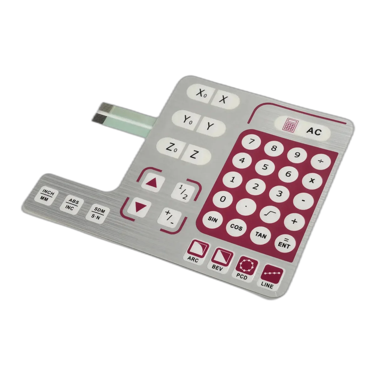
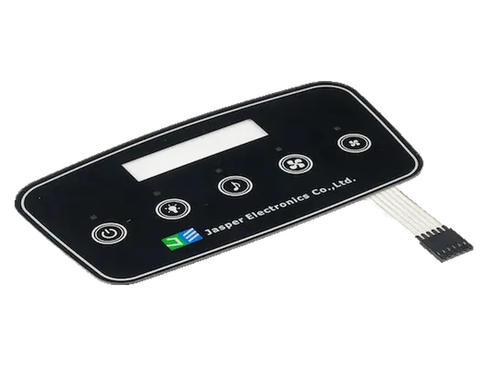
Membrane switch or keypad
Low-profile fixed commands, printed legends, metal or polyester dome options, LEDs, display windows, and a flexible circuit can be combined behind one graphic face.
Release focusRelease tactile target, support, key spacing, force, travel cue, circuit, tail, connector, backer, adhesive, housing flatness, lighting, and controller debounce or response.
- 02
Silicone rubber keypad
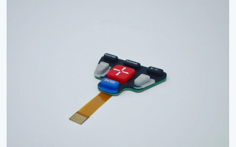
Raised or shaped keys can improve finger location, travel feedback, glove use, curved integration, light piping, and a molded visual language.
Release focusRelease key and web geometry, durometer or feel target, legend route, coating, bezel clearance, compression, PCB contact, light leakage, housing retention, and aging evidence.
- 03
Capacitive or touchscreen interface
A flush face supports changing menus, dead-front graphics, display integration, and reduced mechanical movement when the task accepts electronic feedback.
Release focusRelease cover material and thickness, sensor map, grounding, controller, noise environment, gloves, moisture, edge behavior, target size, display registration, software response, and mounted tuning.
- 04
Hybrid automotive HMI
A display can carry changing information while physical or fixed capacitive controls keep selected actions in stable positions with independent feedback.
Release focusRelease cover or overlay, membrane or silicone keys, sensor, display, PCB or FPC, indicators, backlighting, carrier, gasket, housing datums, cables, connectors, software interface, and test boundary together.
Design one complete action from hand approach to recovery
A control is not finished when its contact closes. The driver or operator must find it, distinguish it, actuate it, see or feel the result, understand the system state, and recover from an incorrect or unavailable action without ambiguity.
- 01
Find
Establish viewing and reach position, hand approach, grouping, edge or texture reference, ambient light, steering or vehicle motion, and whether the user should locate the control without reading every legend.
- 02
Identify
Coordinate icon, word, shape, color, position, texture, backlighting, display label, tell-tale, market language, and function availability. Do not use color alone as the complete message.
- 03
Actuate
Set target size, spacing, force, travel or haptic cue, finger angle, glove condition, repeat rate, simultaneous inputs, accidental contact, long press, double action, and controller threshold.
- 04
Confirm
Connect physical feel to the correct display, indicator, illumination, sound, actuator response, or status change. The visible and tactile result must match the system command and timing.
- 05
Understand
Show active, inactive, selected, unavailable, locked, pending, completed, warning, fault, communication-loss, and service states through the OEM-owned HMI hierarchy.
- 06
Recover
Define back, cancel, retry, timeout, power interruption, invalid sequence, failed actuator, network loss, stuck or missed input, service override, and the safe state selected by the vehicle program.
Approve the panel in five appearance states
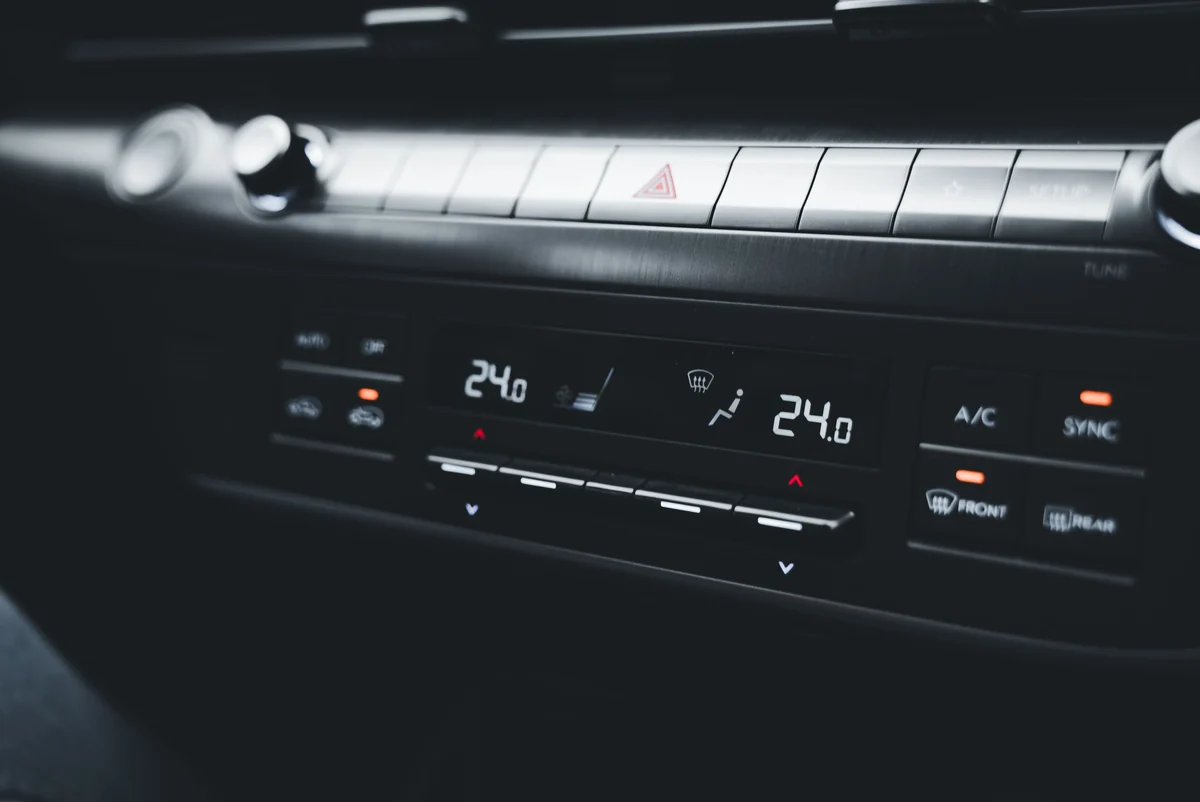
Color approval under a light booth is useful but incomplete. Automotive controls move between unpowered trim, bright solar load, changing daylight, dimmed night illumination, and warning or fault states. Review the powered stack from the installed eye points with the surrounding trim and display active.
- 01
Unpowered
Approve background color, gloss or matte balance, texture, hidden or visible legends, printed mask, window tint, trim match, gaps, edges, contamination, and what must remain recognizable without illumination.
- 02
Bright daylight
Check direct sun, reflected sky, sunglasses where relevant, display and icon contrast, fingerprints, window haze, glare, surface texture, and whether illuminated information remains distinguishable.
- 03
Transition light
Review automatic and manual lighting transitions, threshold behavior, mixed ambient light, tunnel entry, shade, display dimming, and whether controls disappear or bloom during the change.
- 04
Night and dimmed
Set minimum and maximum brightness, group priority, color, diffusion, leakage, hot spots, halo, icon edges, adjacent trim glow, display balance, and dark-adaptation considerations.
- 05
Warning, fault, and service
Freeze indicator meaning, priority, flashing or steady logic, test mode, startup lamp check where applicable, fault persistence, diagnostic state, and what the physical interface shows when software or communication is unavailable.
Send the vehicle state, housing, electronics, variants, and open program requirements for review.
Build the exposure profile from the exact vehicle zone
A dashboard, door panel, exterior charging accessory, workshop controller, and off-road cab do not share one automotive environment. Name the mechanism, mounted orientation, powered state, duration or cycles, recovery, and acceptance evidence before choosing film, ink, coating, adhesive, key material, circuit, connector, or housing interface.
Specify the installed zone before specifying the material.
- 01
Solar heat and temperature transitions
Dark trim under glass, HVAC airflow, cold starts, heated cabins, storage, rapid transitions, nearby electronics, and different expansion rates can change appearance, key feel, adhesive stress, windows, and registration.
- 02
UV and visible-light aging
Dashboard, roof, door, specialty-vehicle, and exterior-accessory surfaces receive different light intensity, angle, heat, and shielding. Define color, gloss, legend, cracking, adhesion, and optical acceptance for the selected method.
- 03
Cleaning, skin products, and vehicle fluids
Interior cleaners, disinfectants, sunscreen, lotions, skin oil, beverages, fuel, lubricants, washer fluid, de-icer, workshop chemicals, and charging-site cleaners require named contact conditions, not a broad resistant claim.
- 04
Abrasion, impact, and cosmetic wear
Nails, rings, keys, tools, dust, grit, wiping, repeated swipes, cargo, footwear, and service removal create local wear paths. Map high-contact zones and approve legends, windows, coatings, texture, embossing, and edges.
- 05
Vibration, shock, and structure
Vehicle motion, door closure, steering input, equipment vibration, housing flex, unsupported keys, connector mass, cable movement, and service handling can change contacts, LEDs, soldered parts, tails, and tactile response.
- 06
Moisture, condensation, and exterior exposure
Cabin humidity, spills, wet gloves, open windows, wash water, weather, charging use, and temperature cycling reach different edges and rear paths. Define the complete installed enclosure and cable boundary.
- 07
Electrical and EMC environment
Power transients, ground offsets, static discharge, radiated or conducted noise, nearby antennas, motors, displays, heaters, and switching electronics affect sensors, LEDs, communication, and false input behavior. The OEM defines the applicable system conditions.
Release the face, housing, circuit, and harness as one interface
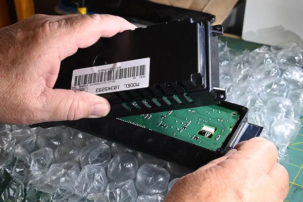
The visible surface depends on what sits behind it. Curved trim, unsupported spans, display openings, sensor ground, adhesive land, FPC bends, PCB height, connector access, and harness motion can change feel, optics, sealing, electrical behavior, and service time.
- 01
Shared datums
Tie visible outline, active keys, display and touch areas, masks, indicator windows, enclosure opening, bezel, carrier, fasteners, PCB, tail exit, and connector position to one controlled coordinate scheme.
- 02
Support and feel
Define backer, boss, rib, cutout, display support, adhesive or gasket compression, bezel clearance, fastener load, hard stops, and local flex under every physical or touch target.
- 03
Surface and bond
Release housing material, surface energy, texture, coating, curvature, flatness, cleanliness, application pressure, cure, temperature, edge geometry, removable protection, and service replacement method.
- 04
Display and lighting stack
Control view area, active touch area, gap, tint, polarizer interaction, mask, sensor border, LED position, diffuser, reflector, leakage barrier, brightness groups, thermal path, and powered inspection state.
- 05
Circuit and grounding
Release schematic or matrix, contact logic, sensor channels, LEDs, components, shielding, ground points, resistance or capacitance limits, controller interface, pinout, diagnostic inputs, and functional-test access.
- 06
Tail, cable, and connector
Show exit, contact side, stiffener, bend radius, slack, strain relief, clamp, sharp edges, heat and moving parts, harness branch, mating direction, latch access, labels, service motion, and replacement unit.
Keep every vehicle and trim variant on one identity ledger
A graphic change can alter control meaning, light transmission, inspection, software mapping, connector identity, or service fit. Link each released interface to its vehicle program, market, trim, language, electronics, and approved sample instead of managing artwork as a loose file.
Vehicle and installation
program, platform, model year, left- or right-hand drive, cabin or exterior zone, housing, mounting, display, carrier, and service unit
Visible identity
part number, artwork revision, language, market icons, color target, texture, gloss, mask, window, dead-front state, trim level, and approved appearance sample
Input and lighting
key map, tactile route, sensor channels, indicator meaning, LED color, diffusion stack, brightness group, dimming reference, fault state, and controller or software mapping
Electrical interface
circuit master, schematic, pinout, tail or cable, connector, contact side, grounding, shielding, component set, test limits, fixture revision, and diagnostic behavior
Manufacturing route
material lot, print and cure route, tooling, lamination, assembly, application method, inspection plan, packaging, traceability, supplier set, and approved deviations
Change and service
reason, affected variants, risk review, validation required, old and new stock, effective point, service interchangeability, labels, records, buyer approval, and field instruction
Define the evidence route before the first production quote
Prototype evidence, production approval, and a running change answer different questions. The buyer should identify the applicable OEM or Tier 1 requirements, documents, special characteristics, submission level, retention, and approval authority at RFQ. JASPER then confirms what can be supplied for the specific program.
JASPER's current quality-management certificate is ISO 9001:2015. IATF 16949 certification, PPAP, APQP, customer-specific requirements, special-characteristic control, capability evidence, and vehicle-program approval are not implied by this page; include the exact project requirement in the RFQ for written scope confirmation.
- 01
Feasibility and architecture
Confirm control allocation, technology, package, materials, lighting, circuit, supplier boundary, regulatory inputs, volumes, variants, schedule, open risks, and the evidence expected from samples.
- 02
Production-intent sample
Build the intended artwork, stack, tooling route, housing or fixture, electronics, cable and connector, then record appearance, dimensions, function, installation, environment, and required revisions.
- 03
Production release
Freeze drawings, specifications, approved samples, inspection and test method, control plan inputs, traceability, packaging, labels, capacity evidence, submission records, and buyer authorization defined by the project.
- 04
Change and continuing supply
Control material, process, tooling, software-linked interface, supplier, location, artwork, variant, repair, deviation, and discontinuation changes through the customer's notification and approval route.
Separate the supplied interface from the complete vehicle HMI
The drawing should show exactly where JASPER's physical component or assembly ends and where vehicle-system responsibility begins.
Released physical interface
- custom graphic overlay, membrane switch, silicone keypad, capacitive panel, printed circuit, tail, connector, LED or backlighting stack, gasket, carrier, and agreed physical HMI assembly
- released material, artwork, dimensions, datums, circuit, pinout, key map, lighting identity, tail and connector detail, cosmetic criteria, component inspection, and agreed functional checks
- design-for-manufacture review, production-intent samples, revision and variant control, packaging, ISO 9001:2015 quality-management scope, and project-defined records
Complete vehicle HMI and program approval
- intended use, driver and passenger tasks, moving or parked availability, controls and tell-tales, human factors, distraction assessment, system safety, alarms, lockouts, and safe state
- ECU, display, controller, firmware, vehicle networks, diagnostics, cybersecurity, power, grounding, EMC, housing, harness, installation, vehicle-state logic, and service software
- applicable regulations, customer-specific requirements, homologation, IATF or production-program route, complete-vehicle validation, production approval, field monitoring, recall, and final release
Qualify a mounted, powered, and software-connected interface
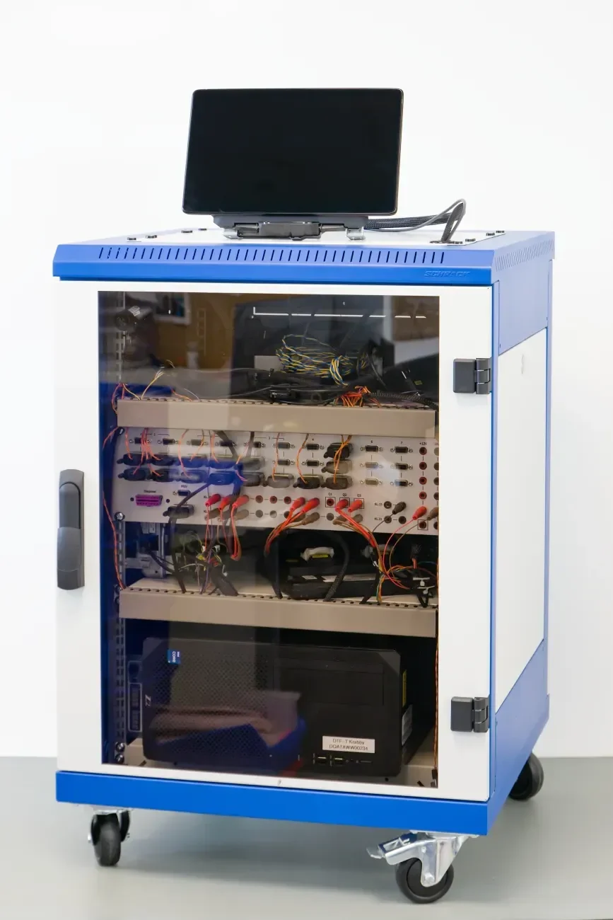
A loose component can prove print, dimensions, key feel, and basic electrical function. It cannot prove cockpit reach, surrounding trim, display registration, night balance, housing support, sensor tuning, harness motion, system feedback, vehicle-state logic, environmental orientation, or service replacement.
- 01
Build the released installation
Use production-intent face, keys or sensor, display, lighting, circuit, carrier, housing, adhesive or gasket, fasteners, tail, harness, connector, controller, software, and trim state.
- 02
Run the action map
Exercise moving, parked, passenger, external, charging, and service functions as applicable, including unavailable actions, feedback, warnings, faults, timeout, network loss, and recovery.
- 03
Approve appearance and feel
Inspect unpowered, bright daylight, transition, night, dimmed, warning, and fault states from defined eye points; measure project-specific force, travel, registration, light, color, and cosmetic criteria.
- 04
Apply zone-specific exposure
Run the named temperature, solar or UV, cleaner and fluids, abrasion, vibration, moisture, electrical, installation, and service conditions on the intended mounted and powered article.
- 05
Release linked evidence
Record post-exposure operation, appearance, optics, electrical state, adhesion, circuit, cable, connector, software reference, variant, drawing revision, test method, results, deviations, approvals, and retained sample.
Production evidence linked to the automotive part identity
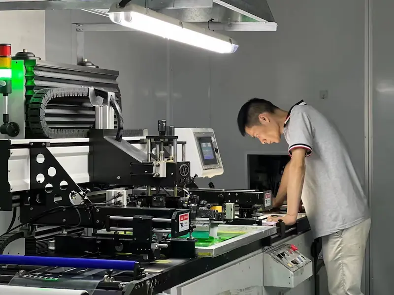
JASPER manufactures the released interface component or agreed physical assembly and records the checks named by its drawing and control plan. Artwork, circuit, lighting, housing interface, tail, connector, option, and revision stay connected to the correct part and variant.
- Identity
- Part and revision, artwork, language, material stack, dimensions, datums, circuit, pinout, lighting, tail or cable, connector, variant, and effective change point.
- Appearance
- Print registration, legends, color reference, finish, window and mask, dead-front state, cut edges, embossing, illumination zones, trim reference, and agreed cosmetic limits.
- Electrical
- Project-defined continuity, open and short, key map, contact, LED polarity and state, touch interface, grounding or shield connection, tail, connector, and assembly checks.
- Mechanical
- Outline, openings, laminate alignment, adhesive or gasket condition, carrier or housing fit, cable restraint, labels, packaging, fixture state, and agreed dimensional records.
Connect the vehicle-zone brief to the right interface route
Product directions
Combine fixed tactile or non-tactile controls with printed icons, LEDs or light-guide options, circuit, tail, connector, and controlled day/night states.
Use molded raised keys, laser-etched or printed legends, light control, PCB contacts, housing integration, and a defined tactile target.
Coordinate a flush custom surface with sensor design, display window, grounding, controller tuning, backlighting, gloves, and mounted behavior.
Define the physical module boundary across overlay or cover, controls, display interface, PCB or FPC, carrier, gasket, harness, connectors, and agreed test.
Engineering resources
Compare LED, light-guide, electroluminescent, fiber-optic, and related routes by icon, area, thickness, color, power, and approval state.
Choose physical feedback from task, target, support, gloves, force, environment, electronics, and complete HMI confirmation.
Coordinate exit, bend, stiffener, pinout, connector, strain relief, harness route, installation, and service motion.
Package vehicle zone, control map, artwork, housing, electronics, exposure, variants, volume, and required program evidence.
Send the automotive interface release package
A useful quotation identifies the vehicle state, installation zone, physical HMI boundary, variants, environment, production program, and evidence expected at sample and release. Early CAD is suitable when fixed and open decisions are marked clearly.
Open Automotive HMI RFQ- 01vehicle or equipment type, installation zone, users, moving or parked availability, action map, feedback, warning, fault, lockout, recovery, language, and market inputs
- 02front panel, display, bezel, carrier, housing, trim, mounting, datums, openings, fasteners, support, flatness or curvature, adhesive or gasket land, and service drawings
- 03membrane, silicone, capacitive, touchscreen, or hybrid direction; tactile target, artwork, icons, colors, texture, windows, masks, dead-front and backlighting states
- 04circuit or sensor, schematic or matrix, electrical limits, LEDs, components, controller, display, grounding, shielding, tail or cable, connector, harness, and test interface
- 05solar, temperature, UV, cleaners, skin products, vehicle fluids, abrasion, impact, vibration, moisture, exterior exposure, EMC inputs, powered state, and acceptance method
- 06program, model year, left or right-hand drive, trim, language, market, electronics, connector, software, service and packaging variants with part-number logic
- 07prototype and annual volume by variant, schedule, tooling, sample evidence, control plan inputs, traceability, change notification, customer-specific requirements, submission level, and approval owner
Automotive Electronics Membrane Switch FAQ
Where are membrane switches used in automotive electronics?
Automotive membrane switches can support fixed controls in center consoles, center stacks, door and seat modules, roof panels, specialty and commercial vehicles, EV charging accessories, service tools, and production fixtures. The correct construction depends on whether the user is driving, parked, outside the vehicle, or servicing equipment, plus the installation, feedback, lighting, environment, electronics, and vehicle-program requirements.
Should an automotive control panel use membrane, silicone, capacitive, or touchscreen input?
Use membrane controls for low-profile fixed commands and printed legends, silicone for raised location and stronger travel cues, capacitive controls for a flush fixed interface, touchscreen input for changing information, and a hybrid when selected direct actions need stable positions beside a display. Decide from function state, reach, tactile confirmation, gloves, contaminants, lighting, housing, electronics, service, and complete-vehicle validation.
How should backlighting be specified for an automotive membrane switch?
Release the unpowered, bright-daylight, transition, night, dimmed, warning, fault, and service states. Define icon and mask registration, LED position, light-guide or diffuser stack, color, intensity range, group priority, leakage, hot spots, adjacent trim glow, display balance, controller or dimming reference, temperature, power, and the production-intent mounted inspection method.
What environmental information is needed for a vehicle membrane keypad?
Identify the exact vehicle zone and provide solar and temperature conditions, UV, cleaners, sunscreen and skin oils, beverages or named vehicle fluids, abrasion and impact paths, vibration and structural support, moisture or exterior exposure, electrical and EMC inputs, storage, powered state, repetitions, recovery, and cosmetic, optical, tactile, electrical, and functional acceptance criteria.
Can JASPER provide PPAP or claim IATF 16949 for an automotive project?
JASPER's current quality-management certificate is ISO 9001:2015. IATF 16949 certification, PPAP, APQP, customer-specific requirements, special-characteristic controls, capability evidence, document retention, submission level, and vehicle-program approval are not automatic product features. Include the exact buyer requirement at RFQ so JASPER can confirm the project-specific evidence and supply scope in writing.
What should an OEM or Tier 1 send for an automotive HMI quote?
Send the vehicle state and action map, installation-zone and housing CAD, display and control layout, artwork and day/night states, tactile requirements, circuit or sensor details, tail and connector route, electronics boundary, environment and test plan, vehicle and trim variants, sample and annual quantities, tooling and schedule, customer-specific documents, traceability and change requirements, acceptance evidence, and responsibility map.