Dongguan, Guangdong 523927, China[email protected]+86 136 3262 5290
Home / Products / Medical Electrode Pads / Custom ECG and EKG Electrode Patches
PRINTED PATCH CIRCUITS FOR OEM MONITORING HARDWARE

Custom ECG and EKG Electrode Patches

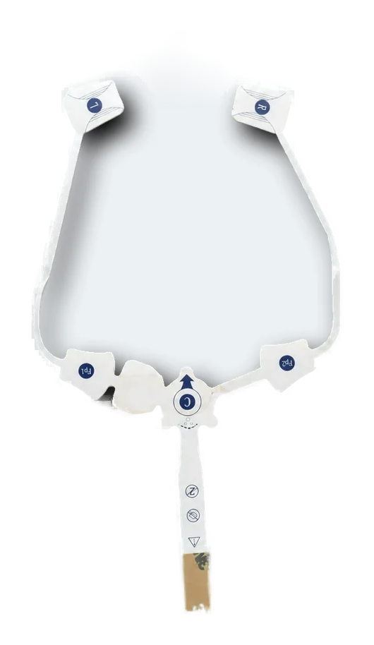
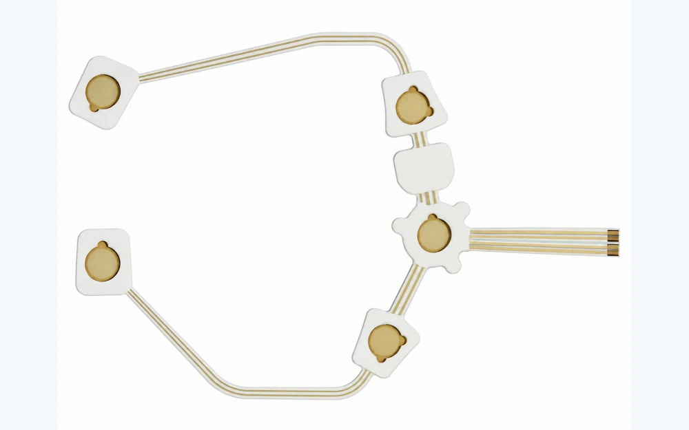
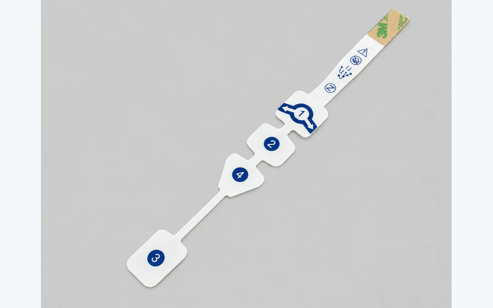
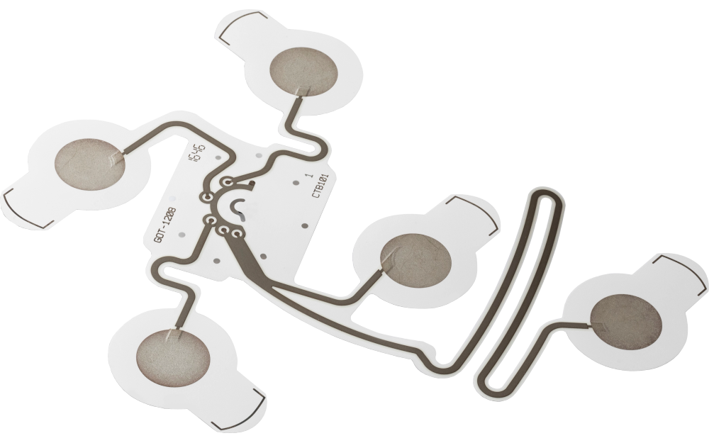
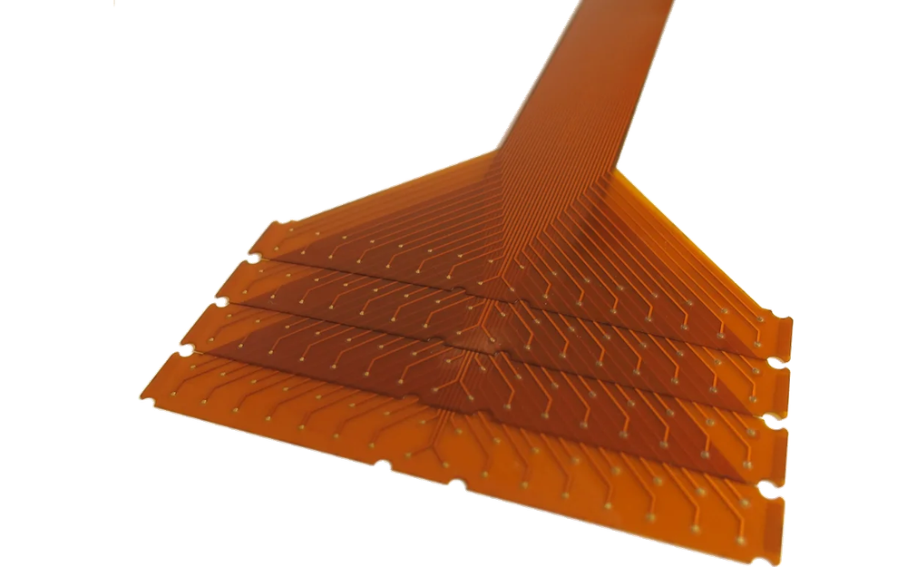
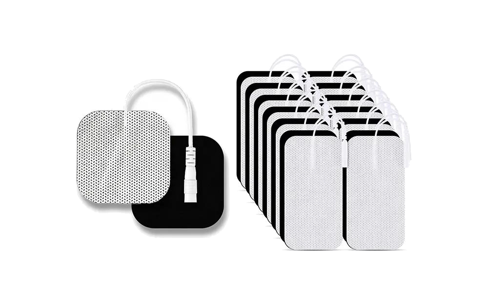
Three custom ECG and EKG electrode patch constructions with printed contact sites

Custom ECG and EKG electrode patches begin with the OEM's contact geometry and acquisition interface. JASPER can print conductive sites and traces, add a snap, tab, tail, or connector relationship, and convert project-specified backing, adhesive or hydrogel zones, reinforcement, liner, labels, and packaging. Signal quality, placement, wear, patient use, and finished-device validation remain with the OEM.

Three custom ECG and EKG electrode patch constructions with printed contact sites
Contact geometry releasedactive area, trace, insulation, snap, tab, tail, or connector
Converted stack controlledbacking, adhesive or hydrogel zones, reinforcement, liner, die cut, and package
OEM signal validation retainedplacement, acquisition electronics, algorithm, wear, claims, and regulatory pathway

The ECG Patch Is a Circuit and Converted Material Stack

A round disposable electrode and a flexible connected patch may serve different equipment architectures, yet both require a controlled active site, printed conductor, connection method, skin-interface zone, backing, liner, and packaged handoff.

The acquisition system determines the electrical and use requirements. JASPER manufactures to released geometry, materials, and inspection methods rather than inferring acceptable contact impedance, signal quality, wear duration, or clinical performance.

Custom ECG and EKG Electrode Patches fit when:

  • the OEM needs a custom outline, electrode-site size, spacing, snap, tab, tail, or connector arrangement
  • printed traces or connected sites must remain registered beneath converted patch layers
  • backing, adhesive or hydrogel zones, reinforcement, liner, and package can be released by project
  • the OEM owns placement, acquisition electronics, signal processing, wear, clinical, and regulatory validation

Six Release Controls for an ECG or EKG Electrode Patch

The patch drawing must connect the skin-facing geometry to the acquisition interface and packaged state.

01

Active contact geometry

Release control

Dimension conductive area, exposed opening, edge margin, center, orientation, and any paired or connected site spacing.

If it is missing

A visually similar patch presents a different effective contact area to the OEM system.

02

Printed trace and insulation

Release control

Release ink, trace width, routing, dielectric coverage, isolation gaps, registration marks, and protected areas.

If it is missing

Conductors are exposed, misregistered, or electrically different from the approved circuit.

03

Snap, tab, or tail handoff

Release control

Name attachment hardware, tail pitch, connector, reinforcement, orientation, mating part, bend zone, and pull method.

If it is missing

The patch passes electrical inspection but does not mate reliably with the customer cable or device.

04

Skin-interface material zones

Release control

Map project-specified adhesive, hydrogel, foam, nonwoven, conductive opening, adhesive-free zone, and liner.

If it is missing

Material overlap covers the active site or leaves an unintended exposed edge.

05

Die cut and assembly datum

Release control

Control outside profile, holes, reliefs, layer overlap, snap location, tail exit, tolerance, and assembly orientation.

If it is missing

The circuit, converted layers, and connector shift relative to one another.

06

Inspection and package state

Release control

Define print, dimensions, continuity, resistance method, attachment, liner, label, count, pouch or tray, and traceability.

If it is missing

Accepted patches arrive contaminated, damaged, unlabeled, or in the wrong handling state.

Release the ECG Patch from Contact Site to Packaged Handoff

Use project-specific values; generic catalog assumptions are not a manufacturing specification.

DecisionOptions to ReviewRelease Question
Electrode layoutSingle site, paired sites, connected strip, custom spacing, reference position, center marks, and placement orientationWhich geometry is controlled by the OEM acquisition design?
Printed circuitConductive ink, substrate, trace width, contact opening, dielectric, resistance method, continuity, and isolationWhat electrical acceptance applies to the supplied circuit?
ConnectionMetal snap, molded snap, tab, printed tail, FPC tail, connector, reinforcement, lead attachment, and mating partWhat physical and electrical state exists at customer handoff?
Converted layersBacking, foam, nonwoven, adhesive, hydrogel, conductive zone, reinforcement, liner, and labelWhich exact materials and zones are included in JASPER's scope?
Profile and registrationOutside die cut, openings, margins, overlap, site position, snap position, tail exit, tolerance, and artwork datumWhich features require fixture-based registration evidence?
Acceptance and packagingAppearance, dimensions, resistance, continuity, attachment, liner, cleanliness, count, pouch or tray, label, and traceabilityWhich checks prove manufacturing and which remain OEM device validation?
Exploded layer stack for a custom printed ECG electrode patch
PATCH STACK

Map Every Layer Around the Active Contact Site

The printed contact, insulation opening, adhesive or hydrogel zone, backing, reinforcement, liner, and snap or tail must share a controlled datum. A small overlap change can alter exposed geometry or assembly handling.

  • mark active and covered conductive areas separately
  • release material zones rather than only material names
  • dimension snap, tab, or tail reinforcement from the contact datum
  • approve the production liner and package with the converted sample
ECG electrode patches arranged for final inspection and packaging
PACKAGED HANDOFF

Inspect the Patch in the State the OEM Will Receive

Electrical inspection should be followed by checks for liner coverage, snap or tail protection, label identity, lot count, package orientation, and handling condition. Those checks support manufacturing control without claiming clinical performance.

  • separate first-article evidence from routine lot checks
  • protect conductive and adhesive zones after inspection
  • retain material, artwork, process, and package revisions
  • define changes that trigger new OEM samples

Move from Printed Geometry to a Controlled OEM Handoff

01

Map the acquisition interface

Release contact sites, cable or device connection, placement references, signal-chain limits, and OEM-owned validation.

02

Build the circuit master

Close conductive geometry, substrate, trace, dielectric, snap or tail, connector lands, and electrical tests.

03

Close converted materials

Release backing, adhesive or hydrogel zones, reinforcement, liner, labels, die cut, and approved sources.

04

Approve packaged samples

Review print, registration, dimensions, attachment, electrical checks, liner, handling, label, and package state.

05

Control repeat production

Lock revisions, sources, fixtures, lot records, packaging, substitutions, notification, and requalification triggers.

Diagnose Patch Problems by Manufacturing Boundary

01

Contact area differs from drawing

Compare print master, dielectric opening, adhesive or hydrogel overlap, die-cut registration, liner position, and inspection datum.

02

Snap or tail attachment varies

Review hardware source, reinforcement, attachment process, orientation fixture, pull method, trace transition, and package protection.

03

Electrical values shift by lot

Check ink and substrate lot, print thickness, cure, trace geometry, contact opening, conditioning, fixture, and measurement method.

04

Patch works in inspection but not in device

Separate manufacturing evidence from placement, cable, acquisition electronics, algorithm, environment, wear, and complete-device validation.

Where Custom ECG and EKG Electrode Patches Fit

01

Resting acquisition systems

Custom contact formats manufactured to an OEM lead, cable, and placement architecture.

02

Ambulatory monitoring hardware

Connected or single-site flexible patches supplied to a released electronics and wear-validation plan.

03

Multi-site monitoring patches

Registered printed sites and routing integrated into one converted flexible construction.

04

Diagnostic equipment accessories

OEM-specific snap, tab, tail, connector, label, and packaged handoff formats.

05

Research acquisition platforms

Custom site spacing and interface geometry for controlled study hardware.

06

Device development samples

Prototype printed circuits and converted patch builds used for OEM evaluation and design closure.

RFQ PACKAGE

Send the ECG Site Map and Complete Patch Stack

A useful RFQ connects the active site to the acquisition interface and package state.

  • active contact geometry, site spacing, orientation, reference marks, exposed openings, and placement relationship
  • conductive ink, substrate, printed traces, dielectric, continuity, resistance method, isolation, and conditioning
  • snap, tab, tail, connector, reinforcement, attachment, mating part, orientation, bend zone, and pull acceptance
  • backing, adhesive or hydrogel zones, foam or nonwoven, liner, labels, skin-contact and non-contact areas
  • outside die cut, openings, layer overlap, registration tolerances, assembly datum, cleanliness, and handling
  • prototype quantity, annual estimate, lot definition, packaging, storage and shipment conditions, traceability, and change control
Send ECG Patch Files

Custom ECG and EKG Electrode Patches FAQ

Can JASPER manufacture both snap and tail-style ECG patches?

Yes, when the project releases the contact geometry, printed circuit, snap or tail construction, reinforcement, mating interface, material stack, attachment method, inspection, and package state.

Can hydrogel or adhesive be included?

Project-specified materials can be included with released supplier, grade, zone geometry, overlap, liner, handling, storage, packaging, and OEM validation requirements.

Does JASPER guarantee ECG signal quality?

No. JASPER can inspect the manufactured circuit and converted patch to agreed methods. Placement, cable, acquisition electronics, signal processing, patient use, clinical performance, and finished-device validation remain with the OEM.

Can several ECG sites be printed on one patch?

Yes, when site spacing, channel routing, dielectric, tail or connector, material stack, registration tolerance, and the OEM electrical acceptance method are defined.

What should the first article include?

It should reproduce production materials, print, contact openings, attachment, converted layers, die cut, liner, label, package, and agreed electrical and dimensional inspection.

Related Electrode and Printed Circuit Routes

Release the contact site, printed trace, patch stack, and acquisition handoff together.

JASPER can review the circuit geometry, snap or tail, converted materials, die cut, inspection, liner, label, packaging, and change-control boundary.

Start ECG Patch ReviewContact Engineering