
State artwork
ControlRelease which icon, ring, slider segment, status field, or dead-front graphic is visible in every operating state.
Failure modeThe production team cannot tell a permitted reveal from unintended show-through.
A backlit capacitive panel combines fixed touch electrodes with illuminated icons, rings, sliders, status areas, or dead-front graphics. Optical layers, light blocks, LED placement, electrical routing, and controller behavior must be approved in both lit and unlit states.
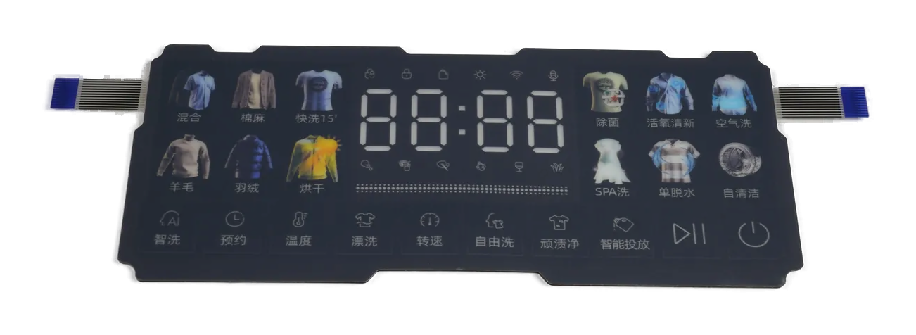
Backlit capacitive panels place an optical system behind or within a printed touch surface so selected graphics become visible under approved operating states.
The visual result comes from artwork apertures, ink stack, diffuser or light guide, light-blocking features, LED position, spacing, carrier, enclosure, drive condition, and viewing setup rather than from the LED part alone.
Electrical routing and switching can also couple into capacitive channels. Lighting approval therefore includes lit and unlit appearance, touch response during state changes, and inspection of representative assembled panels.
A bright bench sample says little about icon shape, off-state concealment, neighboring bleed, or touch behavior in the product.
Release which icon, ring, slider segment, status field, or dead-front graphic is visible in every operating state.
Failure modeThe production team cannot tell a permitted reveal from unintended show-through.
Control translucent and opaque ink regions, color stack, edge definition, registration, pinholes, and powered appearance.
Failure modeThe lit icon changes shape or exposes print variation around its edge.
Define diffuser, light guide, cavity, spacer, reflective surface, air gap, contact points, and assembly orientation.
Failure modeHot spots, shadows, or handling marks remain visible through the finished artwork.
Place walls, opaque layers, printed dams, local shields, and boundaries between neighboring graphics and indicators.
Failure modeOne active LED reveals an adjacent icon or creates a halo in an inactive zone.
Coordinate LED location, PCB or FPC traces, returns, switching, grounding, flex exits, and electrode keep-outs.
Failure modeLighting state changes create false input, lost input, or channel-to-channel variation.
Name lit and unlit references, viewing directions, screen or room conditions, sample state, fixture, and defect rules.
Failure modeA panel approved from one angle fails when installed at the operator's normal position.
The drawing package should connect every visible state to its artwork, optical path, electrical route, and inspection method.
| Decision | Options to Review | Release Question |
|---|---|---|
| Illuminated content | Icons, rings, slider segments, legends, status fields, logos, dead-front reveals, and color states | What must be visible or hidden in each approved operating state? |
| Graphic construction | Transparent, translucent, opaque, color, masking, texture, surface, and registration layers | Which print edges and off-state appearances authorize production? |
| Light distribution | Direct LED, diffuser, light guide, cavity, reflective layer, spacer, local support, and mixed approach | How is each graphic illuminated without exposing the light source or assembly marks? |
| Optical isolation | Printed block, wall, foam, gasket, opaque film, carrier feature, and spacing boundary | What prevents crosstalk between adjacent lit and unlit regions? |
| Electrical integration | PCB or FPC, LED circuit, connector, drive ownership, grounding, touch controller, routing, and diagnostics | Which lighting transitions and power states must preserve touch response? |
| Approval evidence | Lit reference, unlit reference, viewing setup, state sequence, touch test, powered inspection, and retained samples | Which assembled condition and change triggers govern repeat production? |
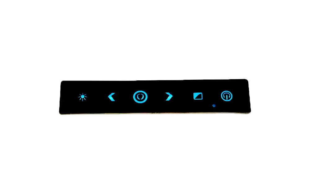
Dead-front artwork can pass in the off state and reveal halos, pinholes, color shifts, uneven edges, or neighboring icons when powered. The reverse is also true: an attractive lit icon may remain too visible when it should disappear.
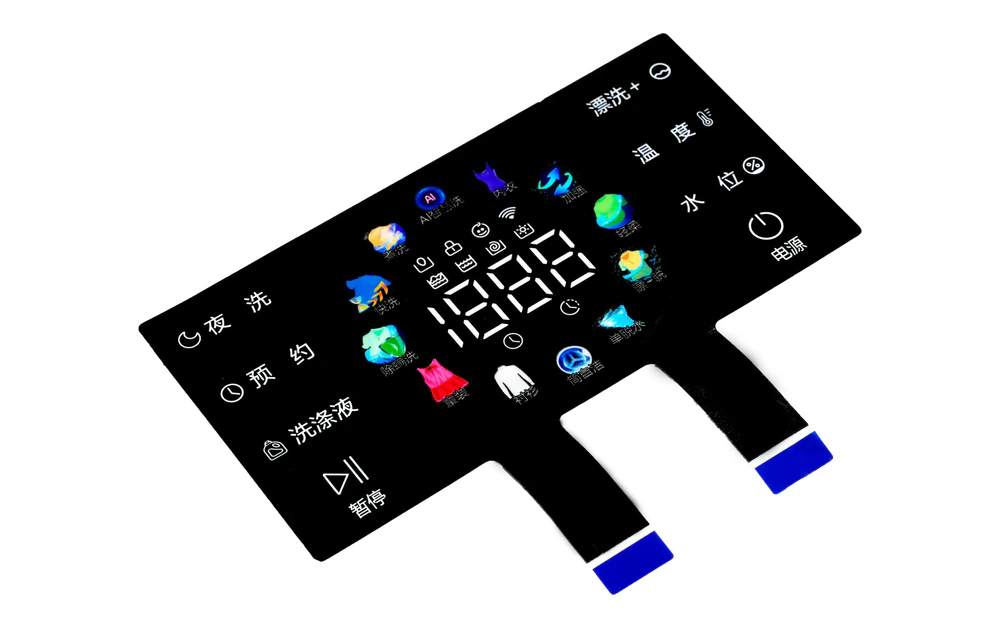
LEDs, switching traces, return paths, light guides, opaque barriers, flex tails, and touch electrodes compete for the same panel area. Their locations should be resolved in one layer drawing before tooling.
List visible and hidden graphics, color intent, sequence, viewing directions, touch actions, and feedback ownership.
Separate opaque, translucent, masking, color, dead-front, surface, and registration layers.
Place LEDs, diffuser or light guide, light blocks, cavity, carrier, adhesive, gasket, flex, and enclosure features.
Compare lit and unlit references, icon edges, crosstalk, viewing behavior, touch response, and lighting noise states.
Release artwork, optics, circuit, controller state, assembly sequence, inspection fixture, retained sample, and change triggers.
Check light blocks, cavity openings, diffuser contact, print opacity, adhesive path, carrier gaps, and LED assignment.
Review LED position, optical spacing, diffuser or guide condition, printed aperture, local pressure, and assembly orientation.
Inspect opaque layers, pinholes, ink registration, ambient reflection, inactive LED leakage, and powered neighboring zones.
Compare LED drive state, switching route, grounding, controller configuration, electrode keep-outs, connector, and host power mode.
Fixed touch controls whose operating states must remain readable in changing work-area lighting.
Dead-front icons, rings, sliders, and status cues integrated into a clean front surface.
Selective illuminated controls coordinated with viewing direction, panel graphics, and installed electronics.
Room, access, and equipment panels using guided icons and fixed capacitive input zones.
Illuminated controls requiring controlled graphics, surface cleaning review, and powered inspection.
Custom state-driven interfaces where artwork, optics, circuit, and touch behavior are released together.
The fastest review starts with what should appear, what should disappear, and which electrical state produces each result.
Project artwork can define icons, rings, slider segments, legends, status fields, logos, or selective dead-front reveals, subject to the available optical and sensing layout.
No universal value is appropriate for this page. The result depends on the selected light source, drive, artwork, optical stack, viewing condition, thermal environment, and project acceptance method.
It is a graphic construction intended to conceal selected symbols when unlit and reveal them in approved powered states. Both conditions require sample approval.
Yes. Switching, grounding, trace location, connectors, drive states, and nearby conductors can influence sensing, so lighting transitions belong in the touch validation plan.
Approve lit and unlit graphics, icon boundaries, crosstalk, viewing directions, optical defects, touch response through state changes, fit, and the released inspection setup.
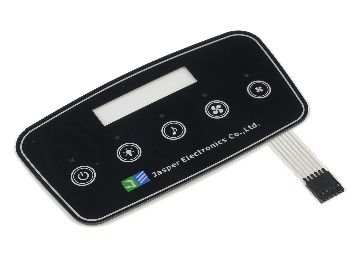
Compare fixed, display-window, PCAP, backlit, and front-panel interface routes.
Review Resource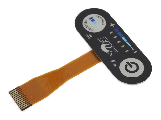
Review fixed capacitive inputs when illumination is secondary or unnecessary.
Review Resource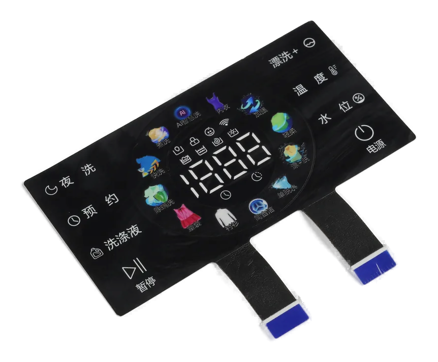
Integrate lighting, sensor, interconnect, carrier, gasket, and physical front-panel test.
Review ResourceJASPER can review illuminated graphics, dead-front behavior, diffusion, light blocking, LED routing, touch noise, viewing setup, and paired lit and unlit approvals.
Share the project basics. JASPER will review the stack, materials, connector, quantity, and production risks.